 |
|
|
|
|
|
|
|
|
|
|
|
|
|
|
|
|
|
|
|
|
|
|
|
|
|
|
|
|
|
|
|
|
|
|
|
|
|
|
|
|
|
|
|
|
|
|
|
|
|
|
|
|
|
|
|
|
|
|
|
|
|
|
|
|
|
|
|
|
|
|
|
|
|
|
|
|
|
|
|
|
|
|
|
|
|
|
|
|
|
|
|
|
|
|
|
|
|
|
|
|
|
|
|
|
|
|
|
|
|
|
|
|
|
|
|
|
|
|
|
|
|
|
|
|
|
|
|
|
|
|
|
|
|
|
|
|
|
|
|
|
|
|
|
|
|
|
|
|
|
|
"Union" was a brand name used until the 1970s by T.S.Harrison & Son and applied to a wide range of items including a number of lighter metal and wood lathes, heavy and light double-ended and single off-hand grinders, precision tool-and-cutter grinders, angle plates, drilling machines, machine vices and many similar machine-tool related parts.
Lathes marketed under the name included the well known "Union Jubilee" and "Union Graduate" wood-turning models, three versions of a Light Pattern Hand Lathe - maker's Type Number L.1.A - and two backgeared and screwcutting models in 3.5 and 5-inch centre heights - respectively the L.1.A.S. and L.2.A.S.
Introduced during 1929, all versions of the L.1. Light Pattern lathe were of identical basic design, with simple, flat-topped, 90-degree edge beds, the "Light Pattern" lathes were manufactured in three versions: 3.5" x 24", 5" x 31" and 6" x 36". Despite the comparatively low prices each was constructed as a unique model - not just modified with castings of varying thickness to make up the centre height - with a headstock (then often referred to as the fasthead) carrying a correctly-sized bearing assembly and a 3-step pulley set to give an appropriate speed range. The smallest lathe had a No. 1 Morse taper, 7/8" x 12 t.p.i. nose, 1-inch wide pulleys and ran at 700, 1400 and 2800 r.p.m.; the middle model used a No. 1 Morse taper 1" x 10 t.p.i. nose, 1.25-inch pulleys and had speeds of 480, 1000 and 2100 r.p.m. - whilst the largest employed a 1.5" x 7 t.p.i. nose, 1.5-inches wide pulleys with speeds of 480, 960 and 1920 r.p.m. The lathes could be bench mounted and powered from a remote countershaft, or supplied on cast-iron legs (or standards in the terminology of the day) for drive by either a foot-treadle and flywheel or from a motor, neatly flange-mounted to the inside rear of the headstock-end leg. Unlike the same arrangement when used on the better-specified 3.5-inch and 5-inch backgeared and screwcutting Union lathes (see below) this motor had no built-on reduction gearbox (with 16 DP, silent-running fibre gears at a 0.3 : 1 reduction) and drove the headstock pulley directly. For each size of lathe the motor power and revolutions varied with 0.5 h.p. 1400 r.p.m., 0.75 h.p. 1000 r.p.m. and 1 h.p. 960 r.p.m. being used for the 3.52, 5" and 6" models respectively. For an extra £2 or £3 the headstock could be equipped with backgear - and thus made far more suitable for heavier metal turning with a slowest speed of around 65 r.p.m. Although supplied as standard with just a T-rest for wood turning a range of extra was available to help improve versatility: longer beds, gap beds, a compound slide rest (without micrometer dials), a sheet-steel chip tray, a fixed steady and the expected range of chucks, faceplates and turning tools. Weights and prices varied widely - from as little as 125 lbs and £8 : 0s : 0d for the smallest bench model to a substantial 500 lbs for the largest stand-mounted version complete with treadle or motor drive: the former listed at £24 : 0s : 0d and the latter almost 50% more at £35 : 0s ; 0d.
Even the tailstocks (termed the loosehead in long-standing English machine-tool parlance) were different with spindle sizes of 0.75", 1" - with No. 1 Morse tapers for the two smaller machines - and 1.25" with a No. 2 taper for the largest. Although listed for more than thirty years production volumes of the Union Light Pattern Hand Lathe must have been relatively low, the last example hanging on in the catalogues until the late 1950s - when it would have been considered hopelessly old-fashioned. However, numbers keep emerging from collapsed sheds and damp cellars so perhaps the writer is being too harsh - for it was certainly well built with some, even in a terribly neglected state, been rescued and put back into service.
Continued below:
|
|
|
|
|
|
|
|
 |
|
|
|
|
|
|
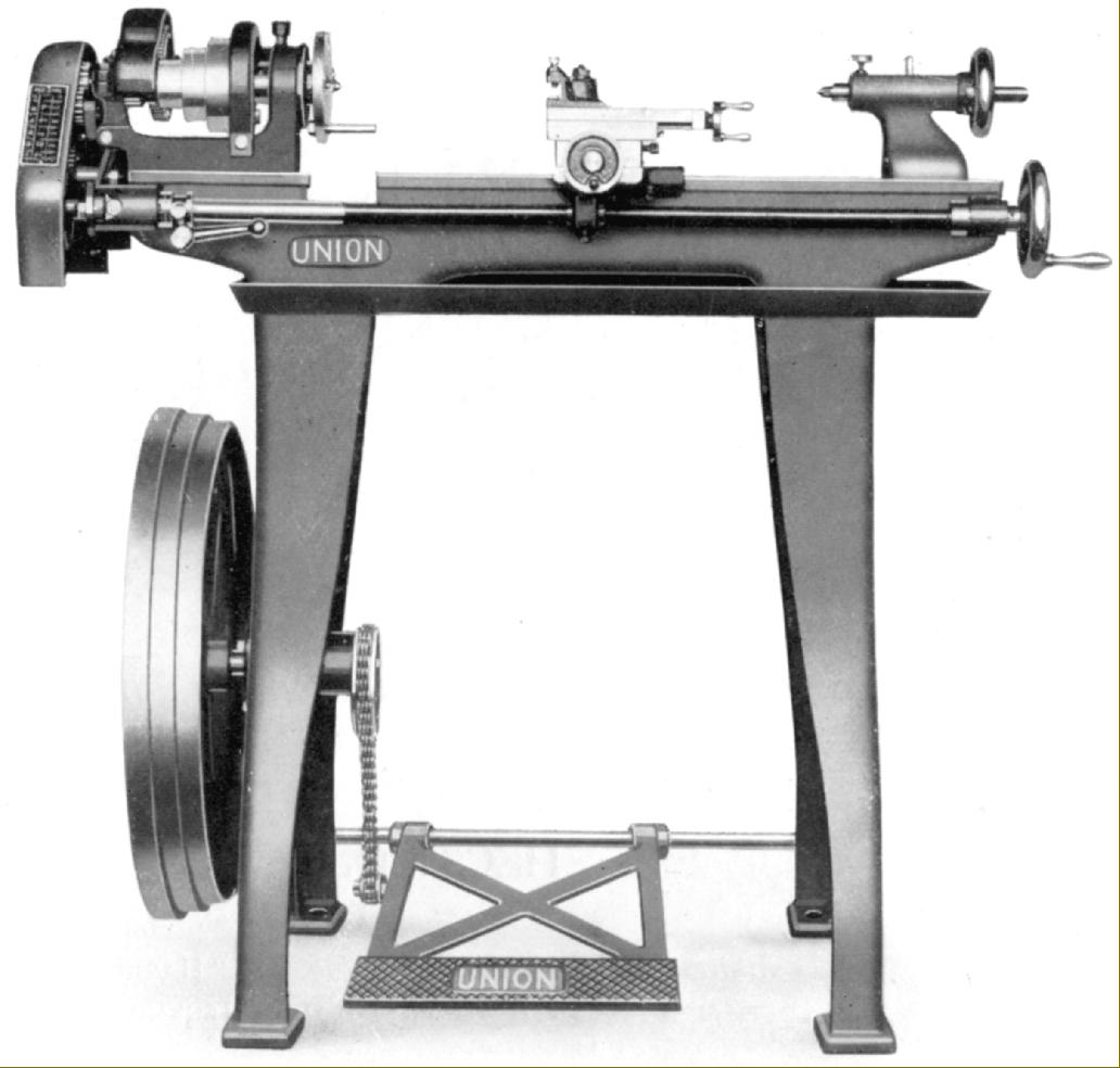
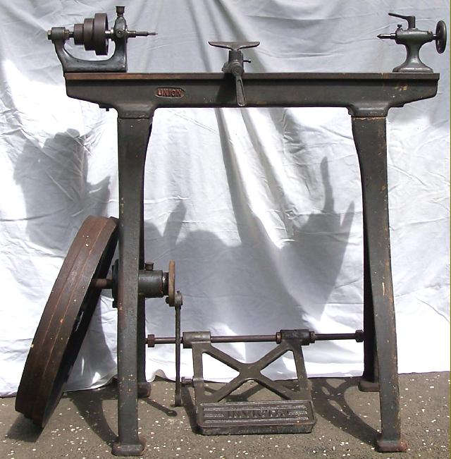
Harrison Union "Light Pattern Hand Lathe " Type L1A with treadle and flywheel drive
|
|
|
|
|
|
|
|
 |
|
|
|
|
|
|
|
|
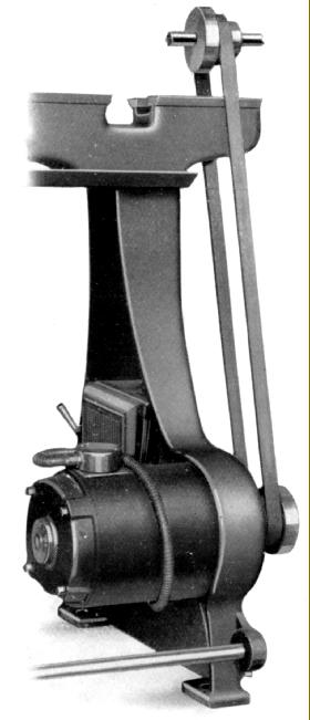
An alternative drive system for the "Light Pattern" lathes was a drive unit using a motor flange-mounted to the inside rear of the headstock-end leg. Unlike the same system when used on the full backgeared and screwcutting models, this had no reduction gearbox on the end and drove the headstock pulley directly.
|
|
|
|
|
|
|
|
|
|
|
|
 |
|
|
|
|
|
|
Continued:
In addition to the "Light Pattern" machines two backgeared and screwcutting Union models were made with 3.5 and 5-inch centre heights. These were not heavy, commercial lathes but economical machines intended for … technical schools, garages, metal workers, amateurs, etc … Though both resembled the light lathes - and used the same form of flat-topped bed but with V-edges to guide the rather short saddle - each was a separate model with no parts in common.
3.5-inch Models:
With a specification that shows it was built down to a price, the design of the 3.5" x 22" Model L.1.A.S. lathe was absolutely typical of its era. While later versions used a relatively large-diameter ball bearing at the front of the spindle, early models were fitted with a plain bearing closed down by twin bolts - though both used the same rather light, single pinch-bolt plain bearing at the rear. Most spindles have been found with the maker's specification of a 3/8-inch bore, No. 1 Morse taper with a 1" x 8 t.p.i. thread, but others are believed to have been used as well - including that found on the 5-inch at 1.25" x 12 t.p.i.. The backgear was the simple kind that slid into place, with engagement possible without the use of spanners - a spring-loaded pin being used to couple pulley and bull-wheel together. Spindle speeds naturally varied slightly according to the type of countershaft used - bench, wall, ceiling, foot-treadle and motor-driven units all being available - but the six available (when driven from a 400 r.p.m countershaft) generally spanned a useful 32 to 800 r.p.m. arranged in geometrical progression. The 3-step headstock pulley took 1-inch wide belt and had diameters of 2", 3" and 4". Unlike many similar lathes that ran their treadle-driven flywheel on plain bearing, Harrison used a pair of ball bearings, fitted a "frictionless" chain for drive - and also ensured that the assembly (with cone diameters of 20.75, 21.375 and 22 inches) was properly balanced. The most sophisticated drive system was unusual in combining electric power and foot treadle - the lathe being equipped with a rheostat-controlled 1/6th h.p. motor fitted with a gear on its spindle that engaged directly with a matching gear cut into the rim of the treadle flywheel. As no guard appears to have been fitted over the large gear, this type might well be referred to as the Union "Knee Planer".
Another up-market drive employed a 0.5 h.p. motor flange-mounted against the inside face of the headstock-end leg and incorporating a reduction gearbox (optimistically termed silent pinions) around its output shaft (illustrated below). The bed was given a permanent gap to swing material 10.5-inches in diameter and the 1" x 8 t.p.i. leadscrew - allowing for the full-nut on the apron - was fitted with a dog-clutch by the headstock and a handle at the tailstock end. To permit the generation of left-hand threads a simple form of reverse was used on the leadscrew drive with a bracket, carrying a permanently-mounted gear, that could be swung into place when required.
Off-set right to the left-hand side of the saddle - to let the cutting tool reach up to the spindle nose across the permanent bed gap - the compound slide rest assembly lacked micrometer dials on both cross and top slide - though most examples have been found with the 6.75" x 3.75" cross slide equipped as a boring table with two large T-slots to the rear of the top slide. Secured with just a single bolt - pressing against an inverted cone - the top slide could be quickly removed; the feed screws ran through replaceable bronze nuts - the makers resisting the temptation to tap these directly into the casting in a fashion then common amongst other purveyors of less-expensive lathes. As a rather nice touch the front of the cross slide was machined away and a rectangular brass plate let in to carry a protractor inscribed with the top-slide set-over graduations.
In the late 1930s the basic bench model sold for £15 : 10s : 0d equipped with a countershaft, the treadle lathe for £17 : 10s : 0d and the motorised version for £ 26 : 0s : 0d. Backgear and changewheel guards were supplied as standard but covers for the drive belts were extra: fifteen shilling for a lower shield or £2 : 0s :0d for full enclosure. The lathe was supplied as standard with a faceplate, two Morse centres, one wood-drive centre, 10 changewheels, a screwcutting chart, spanners and drive belt.
5-inch Models:
Enjoying by far the best mechanical specification of any Union lathe the 5" x 30" model L.2.A.S. was fitted with drive to the 1" x 4 t.p.i. leadscrew through a proper tumble reverse mechanism, single-lever engagement of backgears, clasp nuts on the apron and a bed whose planed top was hand-scraped to an accurate finish. The spindle, with a 1.25" x 12 t.p.i. nose, ran in ball races at both ends - that at the front being a combined radial and thrust unit - with a single-lever enraged backgear ensuring that no fastenings needed to be release before the slow-speed range could be selected. The stand was identical in design to that used on the 3.5-inch model, though the gearbox on the motor-drive type had an output speed of 200 rather than 400 r.p.m. to give spindle speeds that spanned a usefully slow 15 to a inadequately high of 375 r.p.m. Using a 1.25-inch wide belt the cone diameters on the treadle-powered flywheel were slightly altered at 20.75", 21.375" and 22", as were those on the headstock spindle at 2.75", 4" and 5.25".
Basic equipment supplied as standard consisted of: a faceplate, drive plate, a set of (unspecified) changewheels two centres, a travelling steady, spanners and a screwcutting chart. A number of accessories was available for both lathes - the usual chucks, steadies, metric conversion changewheel, turning tools, hand T-rests in two sizes, faceplates, etc - and also a milling slide and a special milling and gear-cutting attachment of the type offered until the late 1960s..
|
|
|
|
|
|
|
|
 |
|
|
|
|
|
|
Union "Knee-planer", a very rare, top-of-the-range 3.5" x 22" gap-bed, backgeared and screwcutting version of the L.1.A.S. . Unusual in having both power and treadle drive, this type was fitted with a rheostat-controlled 1/6th h.p. motor fitted with a gear on its spindle that engaged directly with a matching gear cut into the rim of the flywheel.
|
|
|
|
|
|
|
|
 |
|
|
|
|
|
|
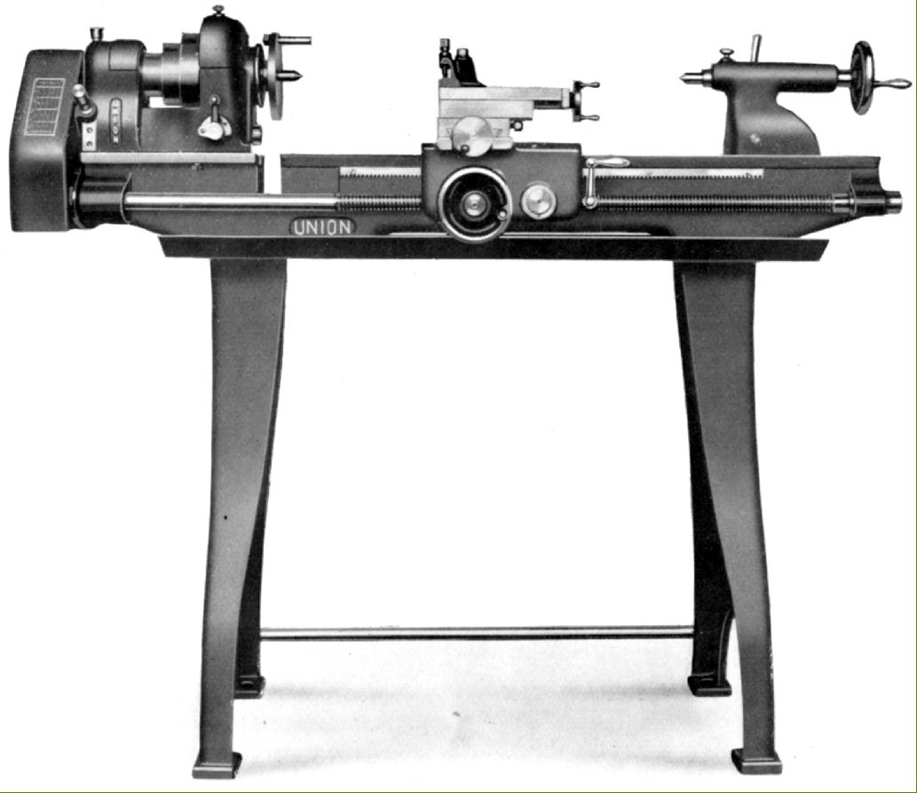
1930s and 1940s Union L.1.A.S. 3.5-inch backgeared and screwcutting lathe with ball-bearing headstock, a permanent gap in the bed, "frictionless" chain drive from foot pedal to flywheel, a full-nut on the apron and a leadscrew with dog-clutch
|
|
|
|
|
|
|
|
 |
|
|
|
|
|
|
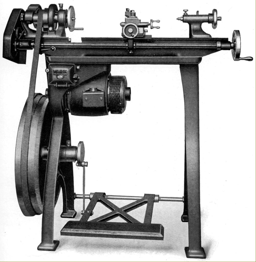
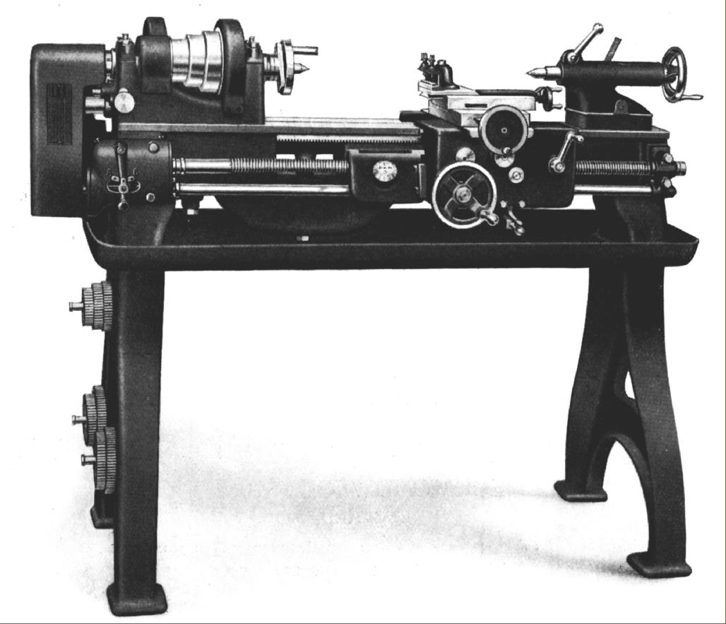
1930s and 1940s 5-inch backgeared and screwcutting Union L.2.A.S. lathe with single-lever backgear, tumble reverse, detachable gap bed and clasp-nuts on the apron. This art-worked publicity pictures gives an impression of smooth finishes and neat detailing - the reality, as shown in the photographs further down the page - was rather different
|
|
|
|
|
|
|
|
 |
|
|
|
|
|
|
By way of comparison here is the contemporary and very much more robust commercial lathe that was made in 4.5 and 5-inch centre heights. Note the many similarities to the later and long-lived L5 series made from the 1940s onwards
|
|
|
|
|
|
|
|
|
|
|
|
|
 |
|
|
|
|
|
|
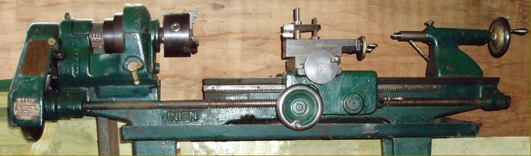
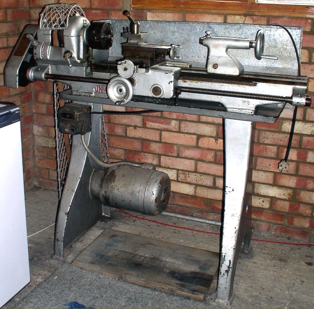
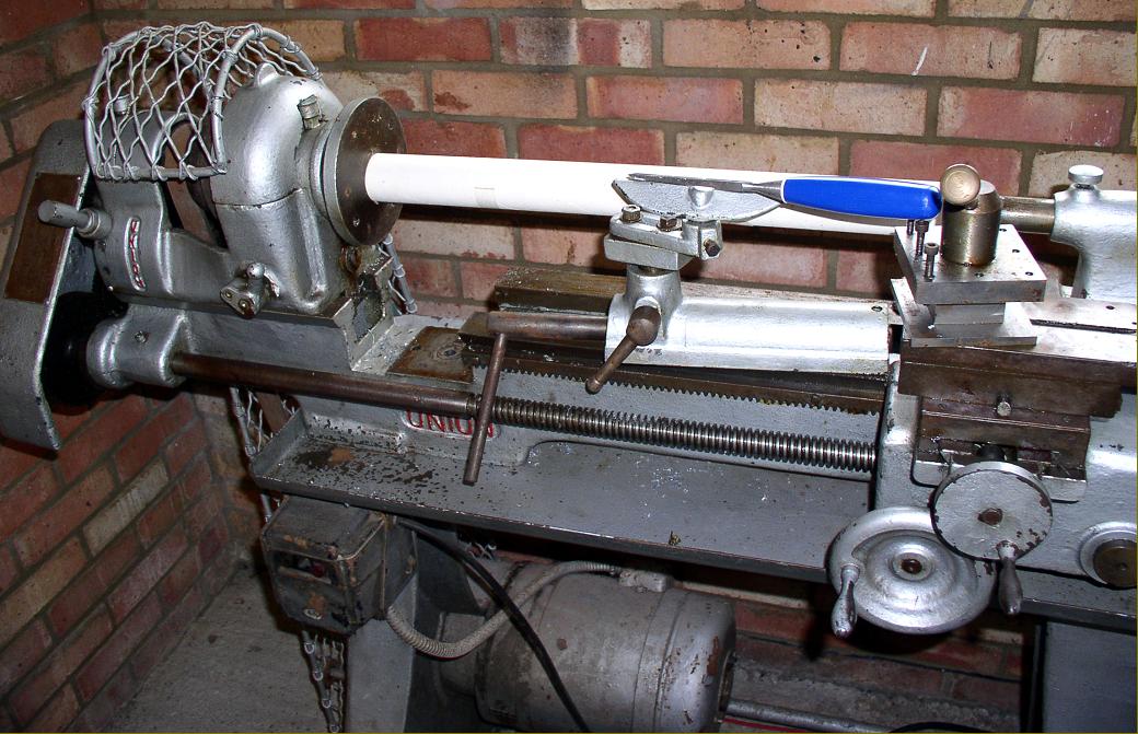
A Union L.2.A.S. 5" x 24" backgeared and screwcutting model believed to have been purchased in 1936
|
|
|
|
|
|
|
|
|
|
|
 |
|
|
|
|
|
|
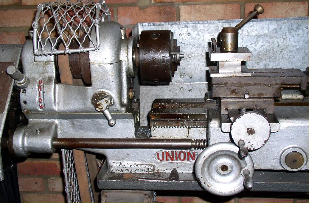
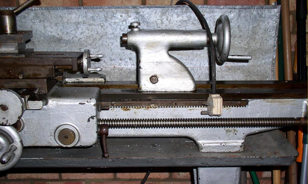
The Union 5-inch could be arranged for underdrive and had a neatly-arranged, single-lever backgear engagement mechanism and tumble reverse. As the photograph shows, the cosmetic finish of the castings left a good deal to be desired.
|
|
|
|
|
|
|
|
 |
|
|
|
|
|
|
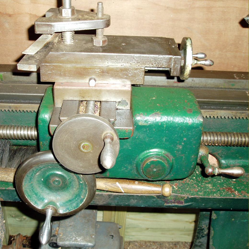
Although well built for an inexpensive lathe some aspects of its detailing were poor with no micrometer dials on the compound rest feed screws nor any protection for the cross-feed screw
|
|
|
|
|
|
|
|
 |
|
|
|
|
|
|
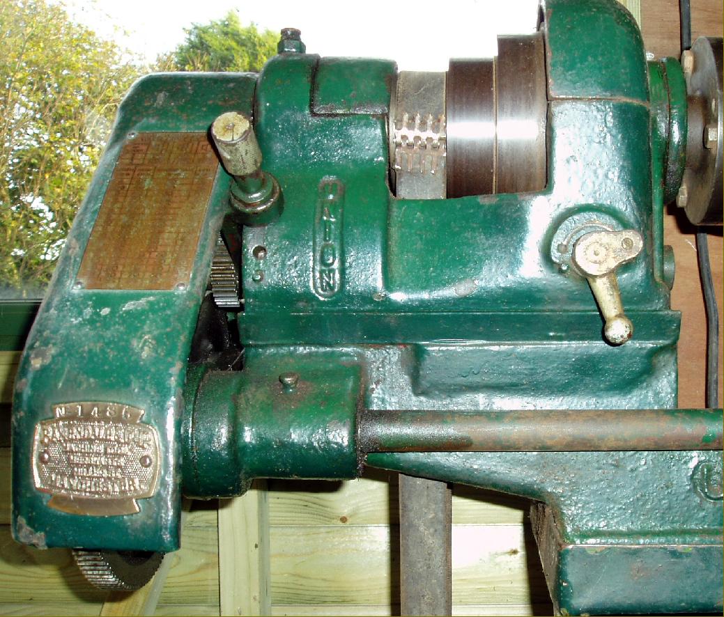
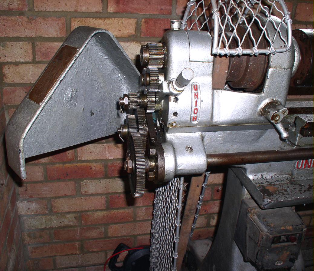
Headstock on an early 3.5-inch with plain bronze bearings. The bracket holding the reversing changewheel for left-hand threading can be seen on the end of the headstock
|
|
|
|
|
|
|
|
|
|
|
 |
|
|
|
|
|
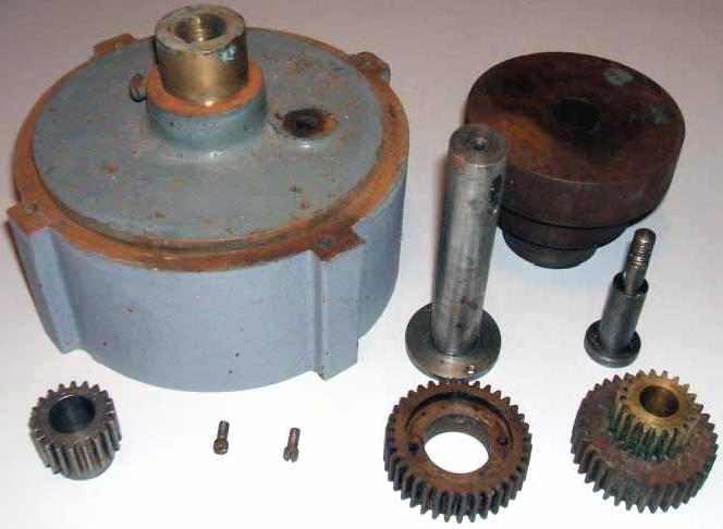
Used exclusively on the better-specified backgeared and screwcutting versions of the Union lathe, a reduction gearbox was fastened to the motor to provide a range of speeds more appropriate for general metal-turning and screwcutting.
|
|
|
|
|
|
|
|
|
|
|
 |
|
|
|
|
|
 |
|
|
|
|
|
 |
|
|
|
|
|
 |
|
|
|
|
|
|
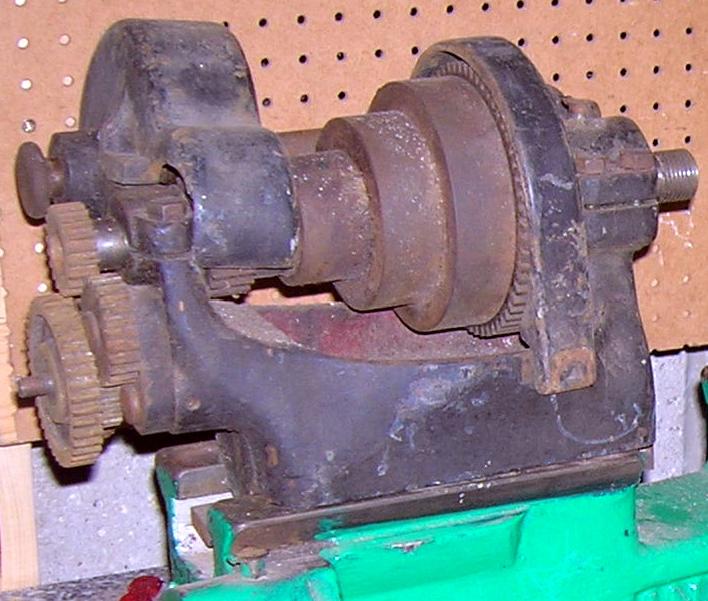
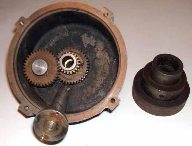
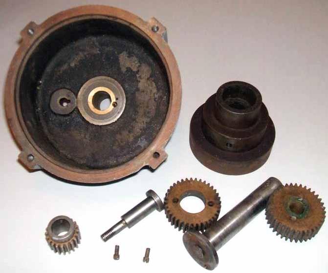
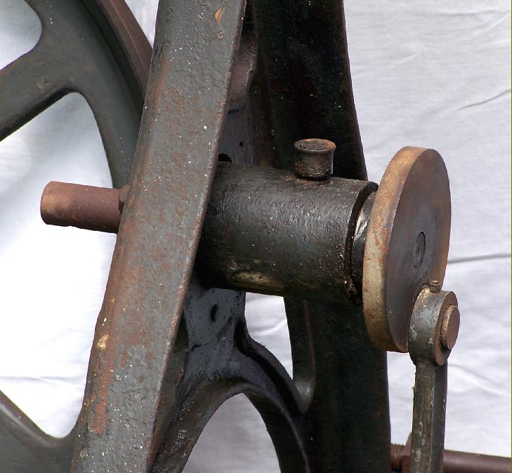
An early Light Pattern 6-inch lathe--probably from the 1920s. Unlike the later models that used a "frictionless" chain drive from foot pedal to flywheel this version was equipped with a plain bushed rod
|
|
|
|
|
|
|
|
 |
|
|
|
|
|
|
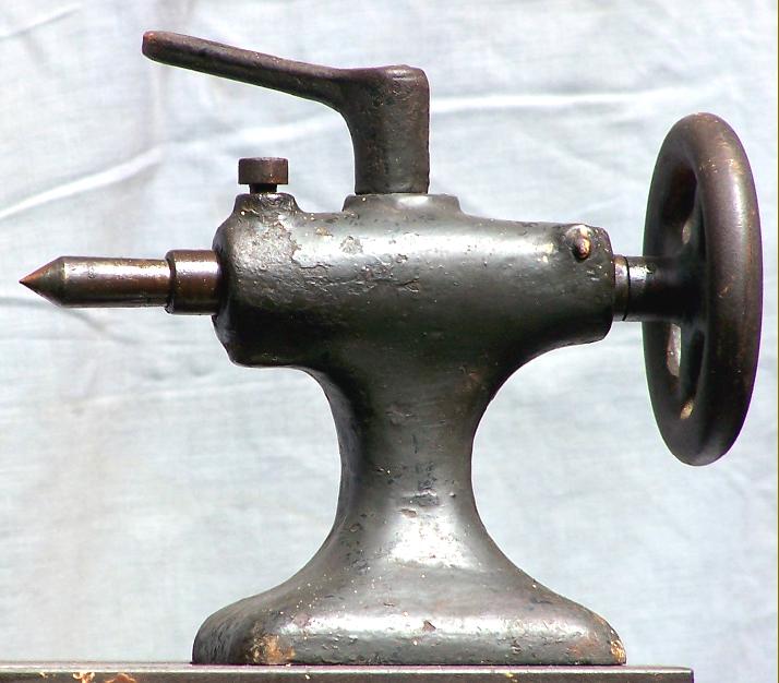
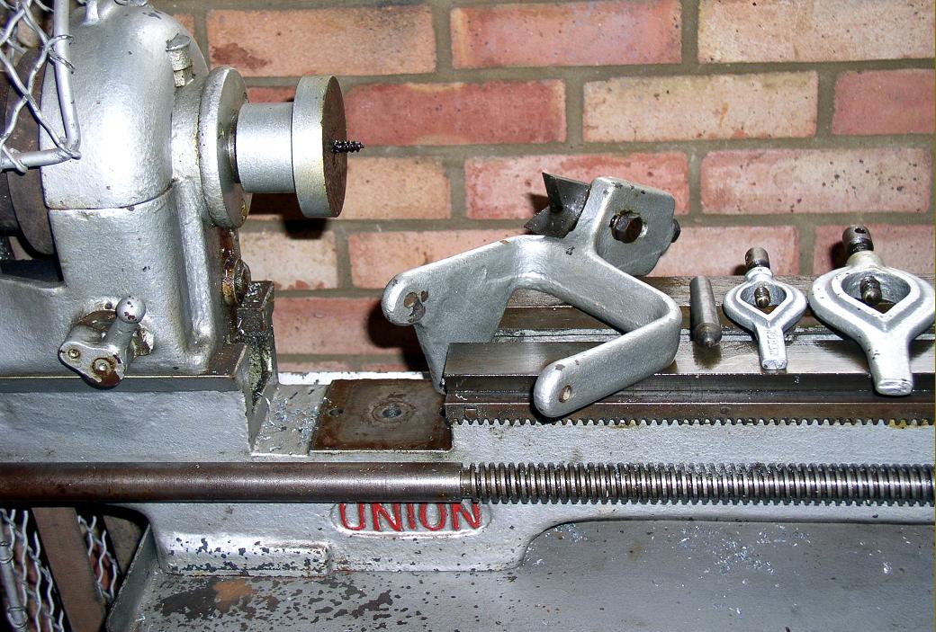
The headstock, with its small, coarse-threaded spindle nose and does not conform to the specification in the 1930 catalogues
|
|
|
|
|
|
|
|
 |
|
|
|
|
|
|
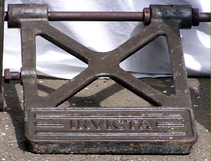
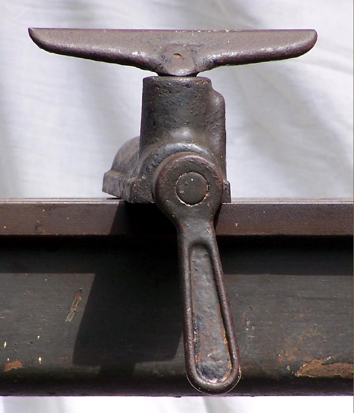
Although this may not be the original treadle plate - changing the name using an easily-replaced parts was often done to ease marketing through larger dealers and distributors
|
|
|
|
|
|
|
|
 |
|
|
|
|
|
|
Decorative flair but insufficient rigidity.
|
|
|
|
|
|
|
|
 |
|
|
|
|
|
|
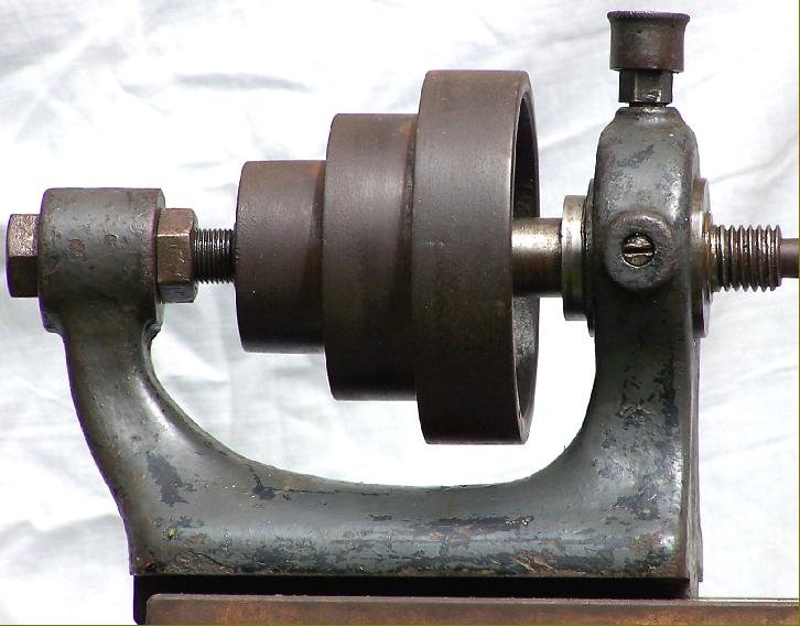
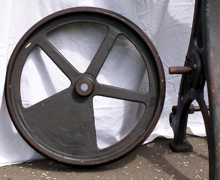
Instead of the commonly-used plain shaft to support the heavy flywheel Harrison employed a pair of ball bearings
|
|
|
|
|
|
|
|
 |
|
|
|
|
|
 |
|
|
|
|
|
 |
|
|
|
|
|
|
Enjoying by far the best mechanical specification of any Union lathe the 5" x 30" model L.2.A.S. was fitted with drive to the 1" x 4 t.p.i. leadscrew through a proper tumble reverse mechanism, single-lever engagement of backgears, clasp nuts on the apron and a bed whose planed top was hand scraped.
|
|
|
|
|
|
|
|
 |
|
|
|
|
|
 |
|
|
|
|
|
 |
|
|
|
|
|
 |
|
|
|
|
|
 |
|
|
|
|
|
|
|
|
|
|
|