 |
|
|
|
|
|
|
|
|
|
|
|
|
|
|
|
|
|
|
|
|
|
|
|
|
|
|
|
|
|
|
|
|
|
|
|
|
|
|
|
|
|
|
|
|
|
|
|
|
|
|
|
|
|
|
|
|
|
|
|
|
|
|
|
|
|
|
|
|
|
|
|
|
|
|
|
|
|
|
|
|
|
|
|
|
|
|
|
|
|
|
|
|
|
|
|
|
|
|
|
|
|
|
In December, 2007 the writer was contacted by an old friend who had just acquired a rather interesting small lathe - made in Derby by Rolls-Royce. Now, Royce may have built their own larger, special-purpose machine tools, and made modifications and adaptations to those from other makers, but they never branched out into production. Hence, the lathes they constructed were not for sale, but for use exclusively within the factory. A total of six were built, in the late 1940s, in response to an appeal from the Experimental Instrument Department, who were finding the usual clock and watchmakers' lathes (BTM, Boley, Leinen, Pultra, etc.) insufficiently accurate for certain critical operations (the writer has spoken to several watchmakers whose experience of 6 mm Lorch and Boley lathes might indicate a problem with their collets becoming inaccurate after prolonged or especially hard use). The first example was designed and constructed by Mr. W.H.R. Clay (CY) , the department head, along lines established by the American WW (Webster Whitcombe) Company with a flat-top, bevelled-edge bed - this example can be seen at the left-hand end of the bench in the first picture below. Having just a compound slide rest that bolted into place, its usefulness was limited and the next stage was to involve one of the clever young men in the department, Mr. Gordon James Hudson (GJH), in the design and construction of the next. This was to use a much more ambitious arrangement, with the carriage (driven by a leadscrew) running on the top and front and back faces of the bed. Following this, a further four examples were made, all of the same design but slightly larger and able to take 10 mm (or 12 mm) collets. To take on the design and manufacture of such lathes, with the intention of producing examples that would exceed the capabilities of those from long-established and highly experienced specialist manufacturers, must have required enormous confidence. It therefore speaks volumes for the technical abilities of CY and GJH (abbreviations like these being the form of nomenclature used within Rolls Royce) that they appear to have been a complete success. A little over six months was spent in design and construction - the reported figure of 1000 working hours presumably being drawn from daily time sheets.
When, in 1957, the lathes were no longer needed, Mr. Clay asked for permission to buy one - and for Mr. Hudson to be allowed to acquire another. While the pink internal memo slips still exist revealing that CY did, indeed, succeed in purchasing one on "preferential terms", no comparable record can be found for Mr Hudson - and it is reported that the others were sent either to the aluminium foundry for use there, or scrapped. However, one more has survived, and today (2012) is in the Derby area in the hands of an R-R employee. If more exist is unknown, but the writer harbours doubts that any were casually disposed of; the 1950s was a time when any small lathe, even a worn out and useless Adept, would have found a ready home and it is not impossible to imagine that out there, somewhere in the UK (and unrecognised) are the remaining examples.
Accordingly, CY took the surviving example home and, on his death in 1990, bequeathed it to Mr. Hudson. A new stand was then constructed, employing the top section of the original countershaft and incorporating storage for the dovetailed 4-drawer accessory tool-box built by apprentices in the R-R pattern shop.
In October 2009, the writer was fortunate enough to be able to interview GJH and his explanations have enabled a much fuller picture of this story to emerge.
Continued below:
Some images below are high resolution and may take time to load
|
|
|
|
|
|
|
|
|
 |
|
|
|
|
 |
|
|
|
|
|
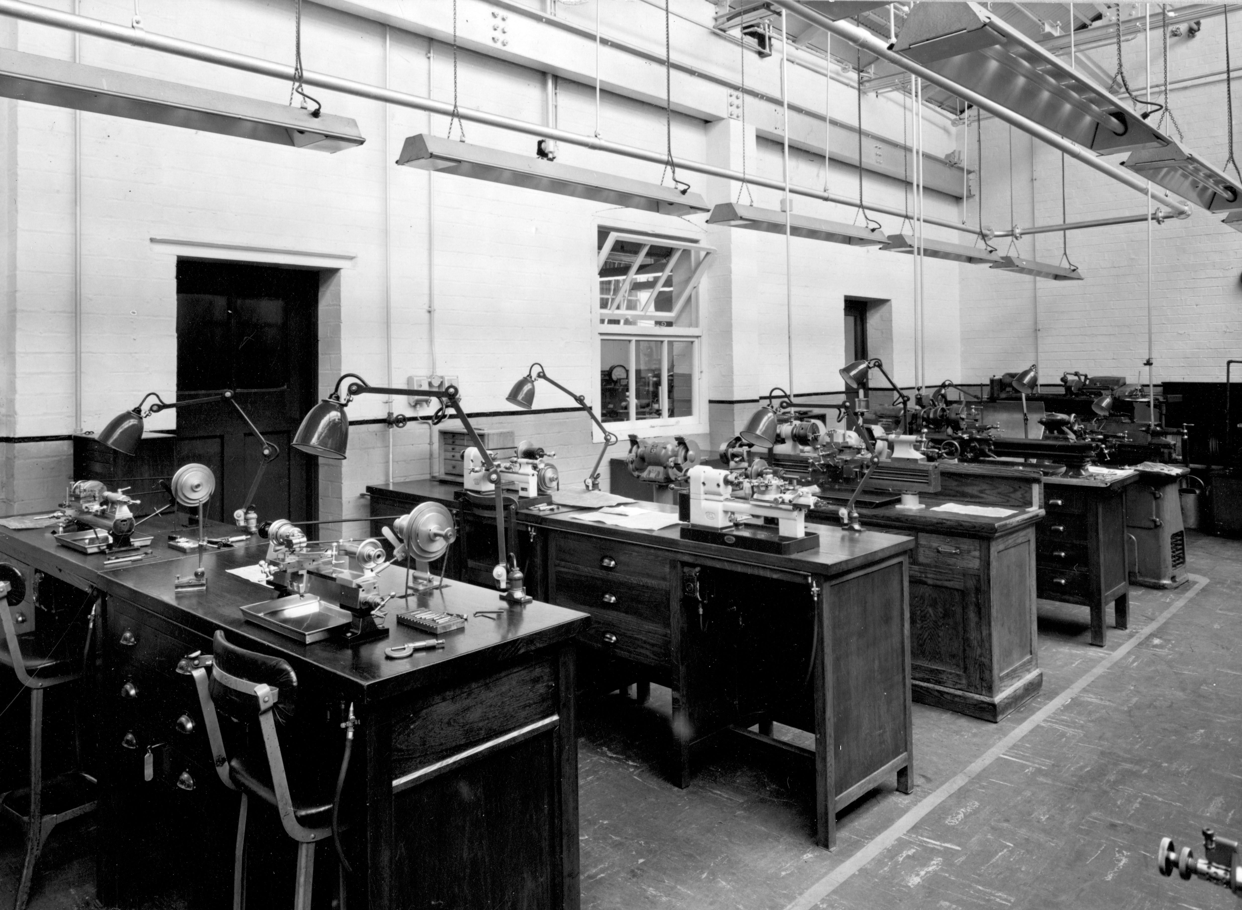
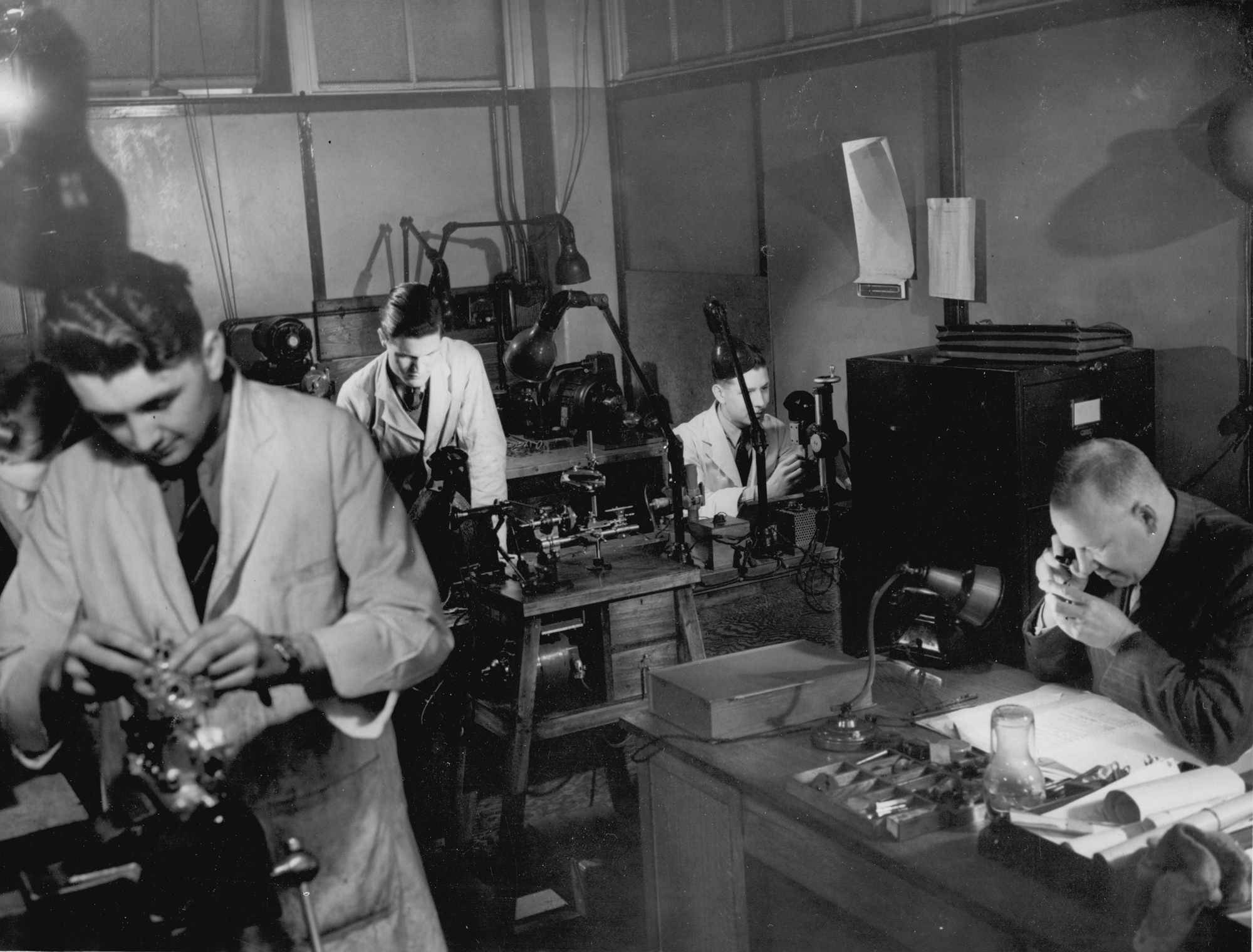
Taken in 1952, this picture shows part of the Rolls-Royce Experimental Instrument Department workshop. The lathe in the immediate foreground, at the right-hand end of the bench, is the second Rolls Royce built by "CY "and "GJH" while to its left is the first example (made by CY and also fitted with 8 mm collets). On the next bench is a pair of Pultra lathes - that on the left a standard 15/50 and on the right a capstan-equipped 15/50 fitted with the maker's raiser blocks. On the third bench is a standard Rivett 608 - in its distinctive "war" finish - with painted instead of polished headstock and tailstock castings - and mounted on its original wooden underdrive cabinet stand. Beyond the Rivett is a long-bed South Bend Model A, with screwcutting gearbox and power cross feed. The lathe at the end is a Mk. 1 Smart and Brown Model M manufactured circa 1947. Further photographs are below.
|
|
|
|
|
|
|
|
|
|
|
|
|
|
|
Continued:
Of the two known surviving examples, the one shown in the colour pictures below was designated by R-R as their Type "GJH" - the appearance of these initials on a surviving general-arrangement drawing being in conflict with previous claims that it was known as the "CY". The lathe was tiny, but crafted like a larger machine with a noticeably robust headstock and carriage assembly. The overall length from collet handwheel to the tip of the leadscrew-feed handle was 25 inches, with the bed accounting for 19 of those. The centre height was 23/8" with 7" available between centres. A letter from Gordon Hudson revealed that the bed was machined from a length of case-hardened nickel steel that was ground and then lapped - with the headstock and tailstock cast from close-grained iron. To the writer's eye, the iron castings look to have been form-milled and hand scraped, in the manner used on Rivett lathes; however, bearing in mind the skill of the builders, it is entirely possible that the fine profile of these units could have been achieved by handwork alone. As a final touch, and to give an exemplary finish, the headstock and tailstock were plated in satin-chrome.
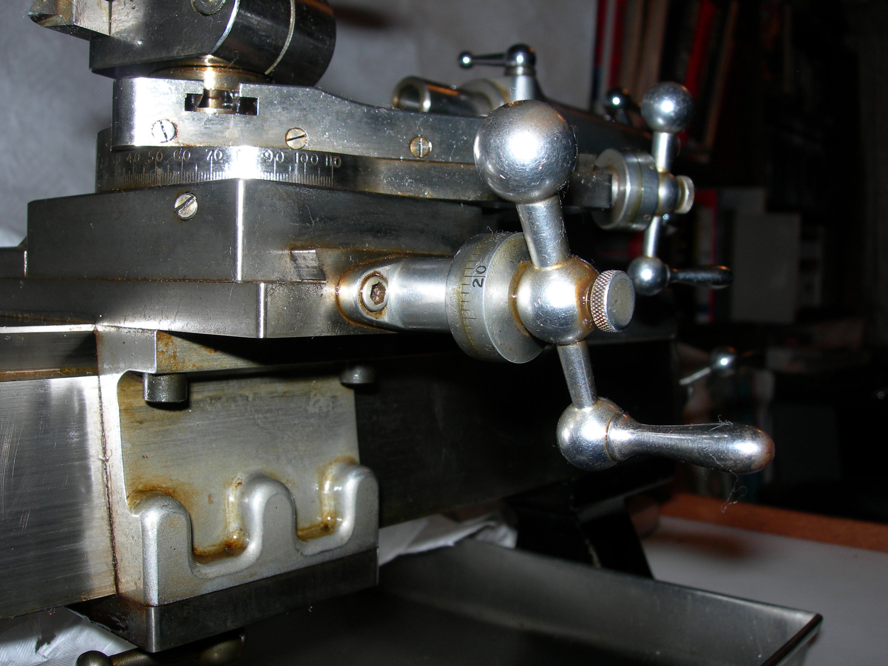
Although later used in a modified form by the Japanese Toyo Company on their precision ML1 lathe, the bed and saddle design of the GJH was, at the time, probably unique - and very interesting. The top was flat and edged with narrow 45-degree V-shaped ways that guided the tailstock and aligned the headstock. The flat front and back faces of the bed sloped outwards (forming a trapezoidal shape) and it was on these, and the top surface, that the duplicated front and rear saddles ran. For such a small lathe the resulting contact area, at around 22 square inches, was enormous and, with the ways extending to the bottom edge of the bed, tremendous support was given to the cutting tool. On the underside of the bed the saddles (formed from castings with bolt-on top and bottom plates made to a dead fit), appear to have been located against an inner vertical surface by one face of the bronze feedscrew nut. The carriage was moved by a graduated handwheel at the tailstock end that drove a feedscrew running centrally down the bed gripped by the bronze nut set immediately below the toolpost. Because of this construction, and doubtless very careful assembly and fitting, the carriage moved with the slightest touch on the handle, yet had absolutely no play.
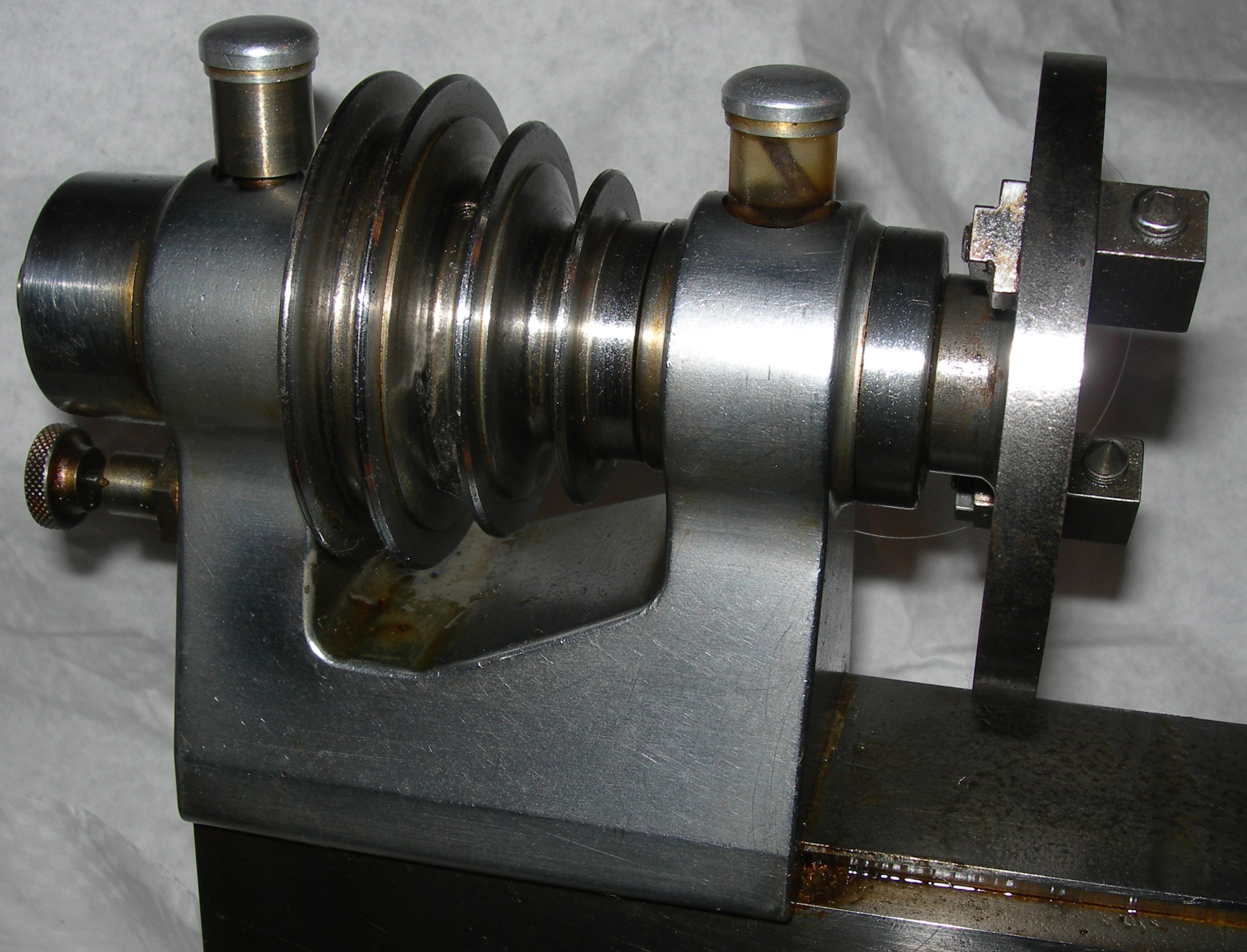
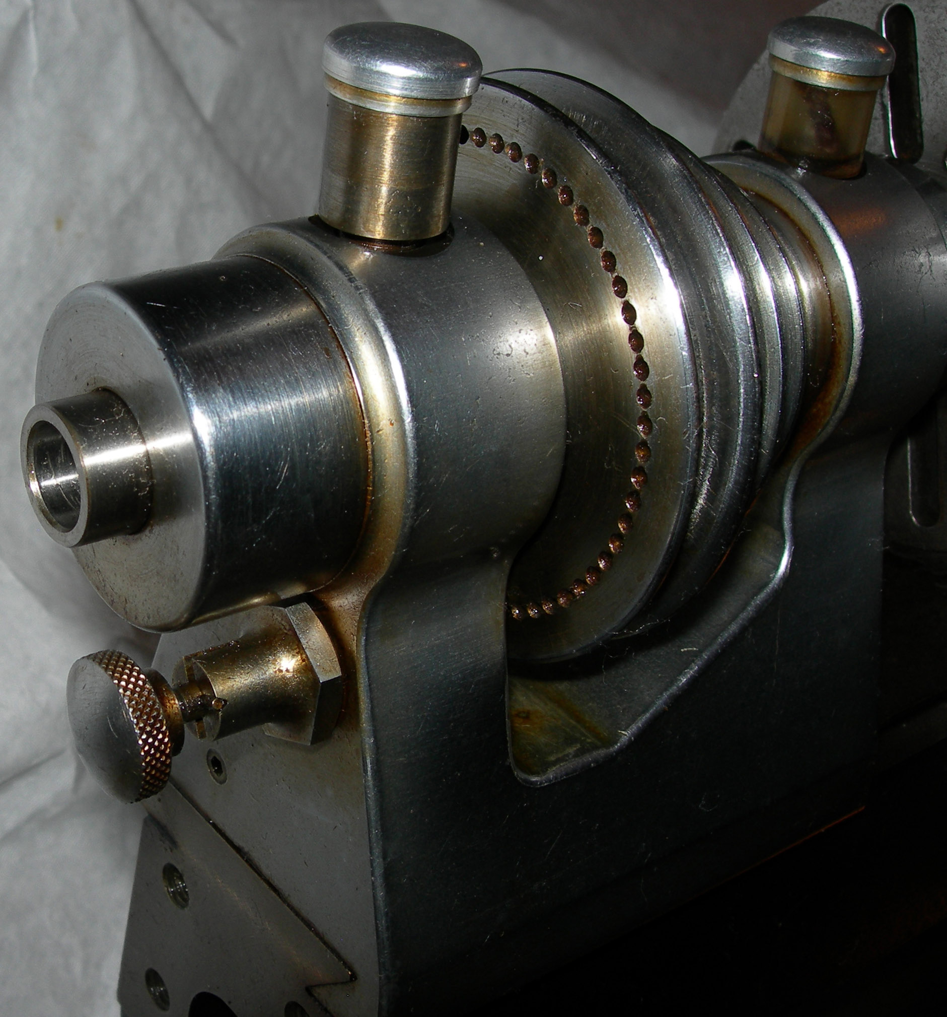
Running in traditional, adjustable, hardened steel plain bearings - conical at the front with a steep taper and at the rear with a parallel bore but sitting in a tapered housing - the hardened, ground and lapped headstock spindle carried a threaded nose and accepted 8 mm draw-in collets. Simple and reliable wick-feed oilers provided lubrication. The 3-step pulley took a round belt and was arranged with its largest diameter to the left, with the outer flange pierced by a circle of 60 indexing holes; these were engaged by a particularly strong, spring-loaded pin that passed through the left-hand wall of the headstock.
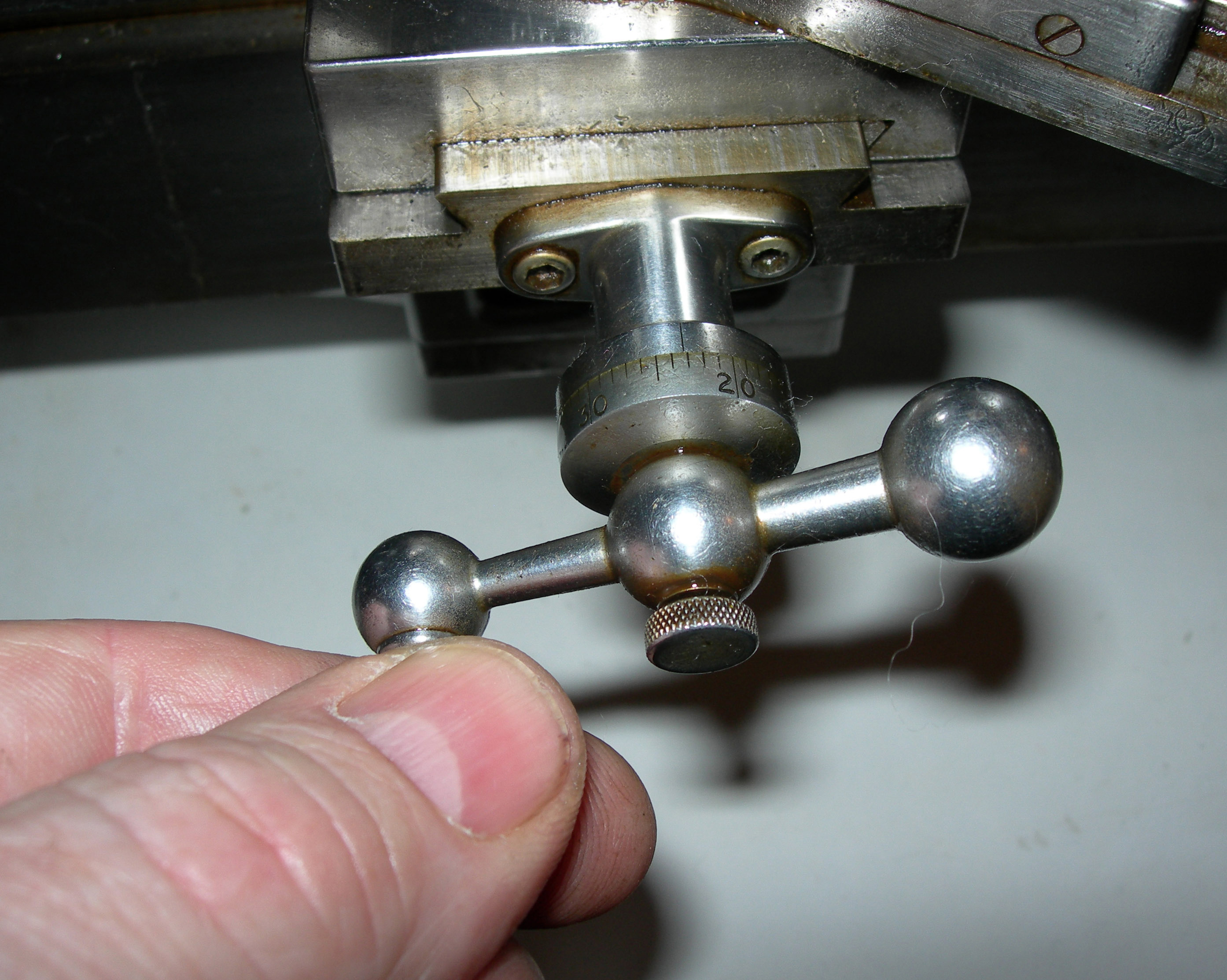
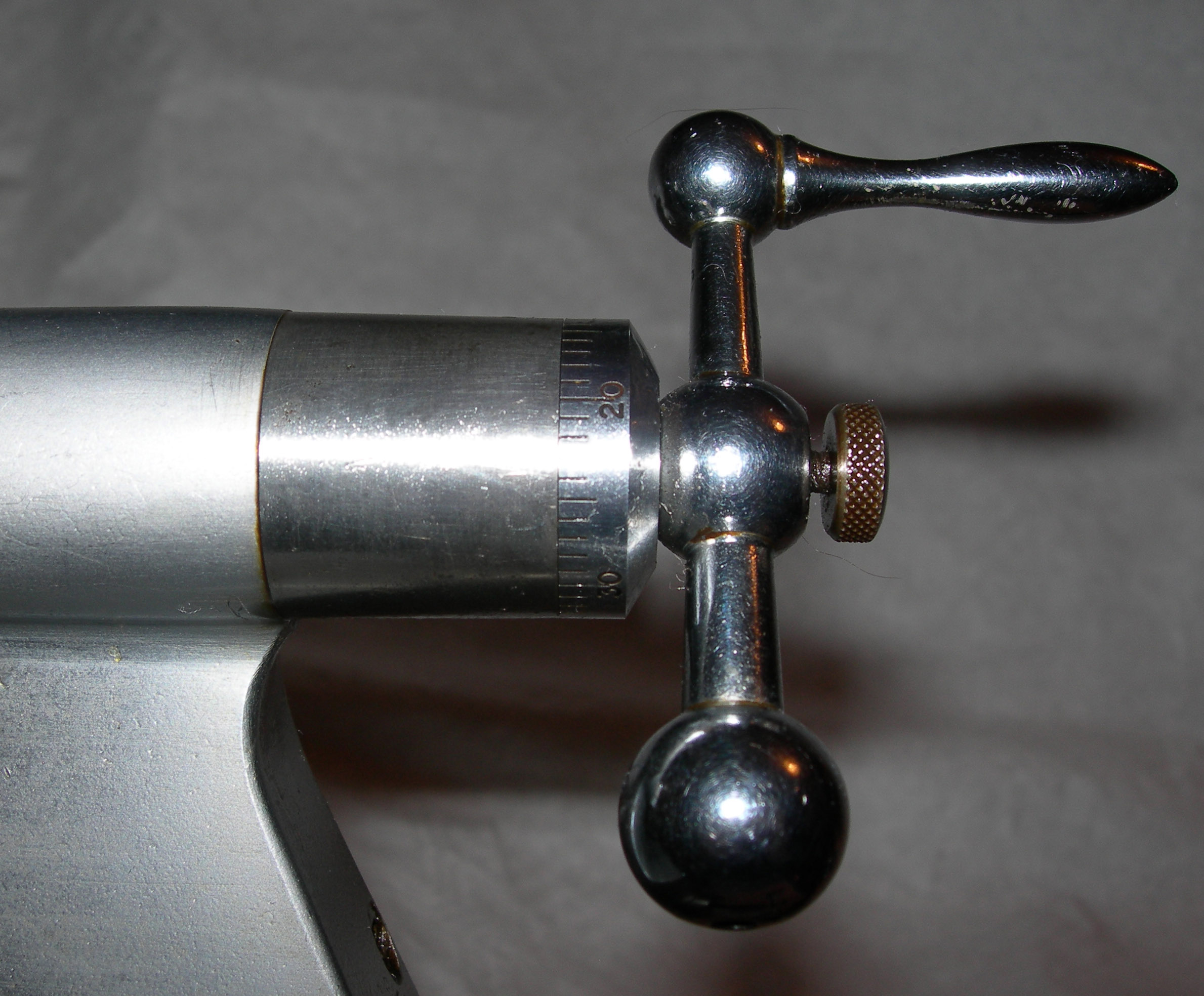
Conventional in appearance, though beautifully finished in polished steel, the cross and top slides were broad and with sufficient gib-strip adjustment screws to ensure that the setting would be absolutely precise over their full length. The cross slide had a travel of 2 inches, the top slide 1.5 inches with their feed screws made from hardened nickel steel. The 0.001" graduated micrometer collars were also hardened and could be locked by small, knurled-edged finger screws that ran through the centre of the handles. By causing the dial to travel axially (with no tendency to cause a tilt over or sideways move as conventional locking screw are prone to), this arrangement avoiding any alteration in the setting. Even the balanced ball handles were special and, reflecting Rivett practice, were retained not by a crude taper pin but by screws that passed neatly down the shank of each ball-ended shaft. A form of "Norman Patent" toolpost was used, (identical in concept to that used for many years on the post-1924 Drummond M-Type) but much improved by Mr. Hudson. Like the ordinary "Norman" it could be both quickly altered in height and swivelled around its mounting boss - but with the added sophistication that the whole unit was self-contained and could be instantly released and slid out of its T-slot holder. Releasing the lock-down handle enabled four coil springs to lift the assembly, the height setting then being finely adjustable by a knurled ring at the top. It's possible that, like many precision lathes, two tailstocks would have been provided, each with 1.5 inches of barrel travel: one took a Morse taper centre the other being adapted for 8 mm (draw-in) collets. Both tailstocks were designed so that their centres could meet that of the headstock, yet still leave sufficient room to use a range of slide-rest movements.
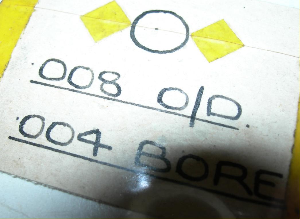
As an example of what the lathe could produce, a sample was retained of a minute bush: just 0.025" long with a diameter of 0.008" and a 0.004" bore. Still in existence, it requires a powerful magnifying glass to appreciate..
|
|
|
|
|
|
|
 |
|
|
|
|
|
|
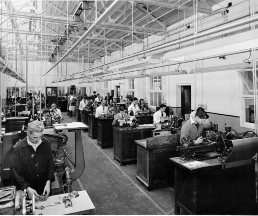
Another view of the Rolls-Royce Experimental Instrument Department workshop. Lathes on the right (as described in the picture at the top of the page) and precision grinding machines on the left. In the far background, by the office door is Gordon Hudson (in a suit) talking to Eric Aitcheson (in white overalls).
Photograph from Les Simms who writes:
Tony,
I was fascinated (and surprised) to find detailed information on the Internet regarding the precision lathes made and used in the Experimental Instrument Department at Rolls Royce as I worked there for a while during my apprenticeship in the early 1950s. Somewhere I have a photograph of the department which includes personnel as well as some of the machinery including the lathes, and I will look this out and send you a copy.
I worked on precision grinding, those machines being to the right of the lathes and just out of shot in your photograph at the top of the page.. All kinds of grinding was done - optical, centreless, etc. - but all small precision work which the conventional machines, out in the Experimental Main Machine Shop (through through the window) could not handle. Any work not officially authorised, was booked to a Ministry order numbers - in other words you could get anything made here, mostly on the night shift…..
It was a great place to work and I knew Mr. (Reg?) Clay who was known as "Bodger" by the lads, Gordon Hudson, (Foreman) who always wore a white overall. There was a charge hand whose face I remember, but forget his name. There was also a draughtsman, Les Betterton who died last year (2016) I believe.
Apart from the machine section we also had a Fitting Department and upstairs a Heat Treatment Facility .The department was attached to the main Experimental Machine Shop at Nightingale Road.
On my 18th birthday it was decreed that I would go onto nightwork (i.e. fortnights about) and this did not work out for me as I was attending Derby Technical College on day release (ONC/HNC) on one day per week and had the choice of having the night before or the night after off.
On one occasion, after being at the College all day, I fell asleep whilst at the machine. As a result I asked for a move into the drawing office - and in fact moved to the Experimental Drawing Office which was also attached to the Experimental Machine Shop at Nightingale Road. This was a tool-design office and my last job there before going into the RAF for National Service was to draw up the layout for the new Experimental Machine Shop which was being built at Sinfin. This involved measuring each and every machine, drawing them to scale as cardboard cut outs and arranging them on the plan. The move took place whilst I was away in 1956 - I still have a copy of the plan.
On my return from National Service, I went back to the Experimental Drawing Office for while but then moved to the Test Facility Design, Compressor Development and finally became Test Facilities Quality Manager until my retirement in 1990.
Happy memories - Rolls-Royce was a great place to work - I made lots of good friends, and here was an expert on every subject under the sun, quite apart from developing aero engines!
|
|
|
|
|
|
|
|
|
|
|
|
|
 |
|
|
|
|
|
|
|
|
|
|
 |
|
|
|
|
|
|
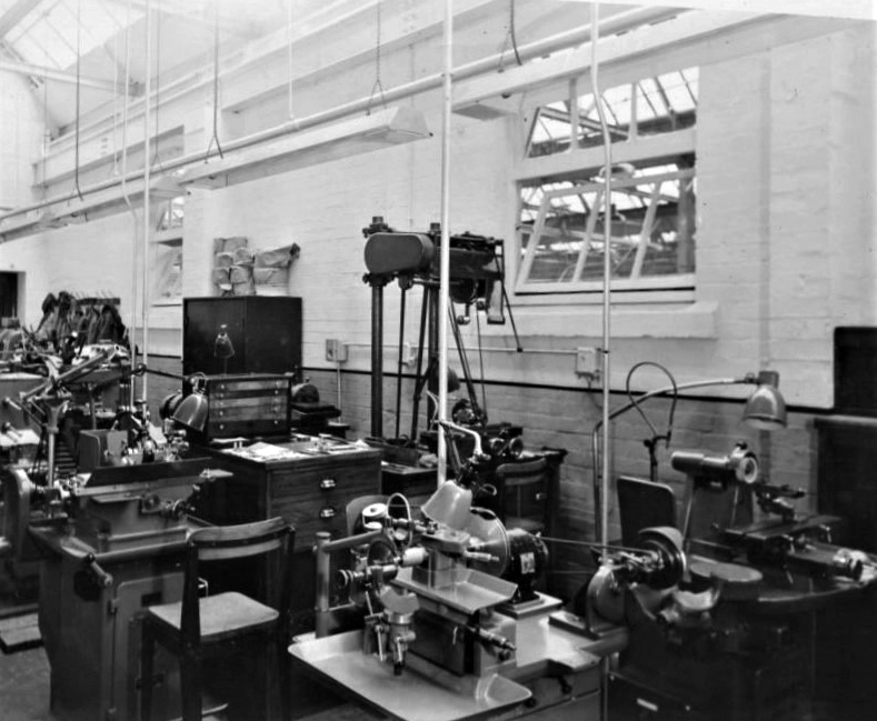
16th April, 1943 and a young Mr Hudson works at a bench in the foreground. Sitting at the desk is Mr. W.H.R. Clay ("CY"), designer of the first R-R lathe. The watchmaker's lathe in the middle of the photograph looks to be a pre-war Lorch
|
|
|
|
|
|
|
 |
|
|
|
|
|
|
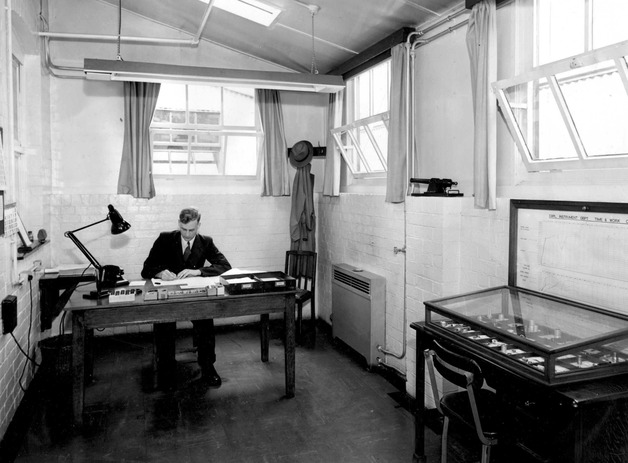
Possibly 1953 - and a more senior Mr Hudson at his desk in the strictly functional office used by the Experimental Instrument Department. On a shelf to the right can be seen a canon, used to conduct early tests of compressor blades. At the time, jet engines were being developed to use centrifugal instead of axial compressors but concerns were raised about the effect that a detached blade might have. Fearing that such a loss could cause the whole assembly to fail, it was decided to conduct some destructive testing and Mr. Hudson was asked to make a suitable cannon to fire an assortment of 2BA nuts and bolts into a compressor disc blade running at 29,000 r.p.m. Far from causing the blades to detach, the bolts simply embedded themselves in the disc material - and development proceeded. Of course, it would have been possible to make just a simple "test-rig" gun but, this being Rolls Royce, a proper job was done that both worked while also being aesthetically pleasing.
|
|
|
|
|
|
|
|
|
|
|
|
 |
|
|
|
|
|
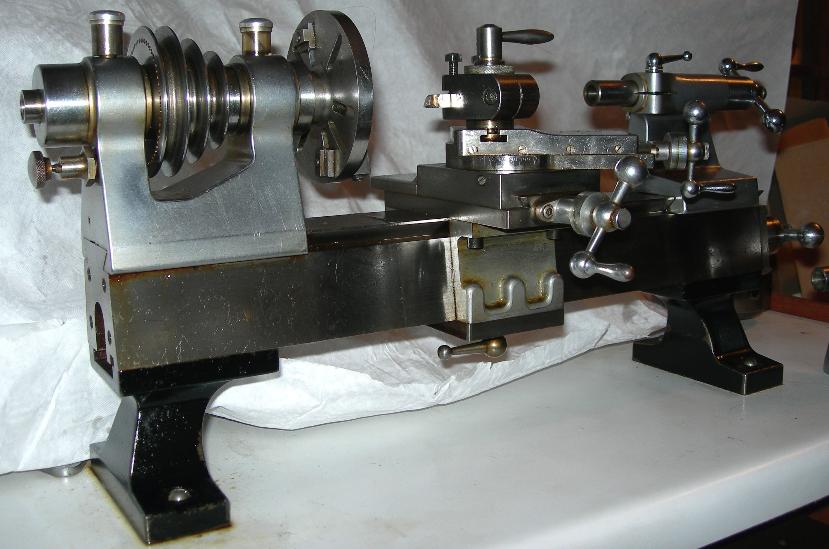
At first sight the R-R 8 mm lathe presents an interesting picture: tiny, but crafted like
a larger machine and with noticeably robust headstock and carriage assemblies.
|
|
|
|
|
|
|
 |
|
|
|
|
|
|
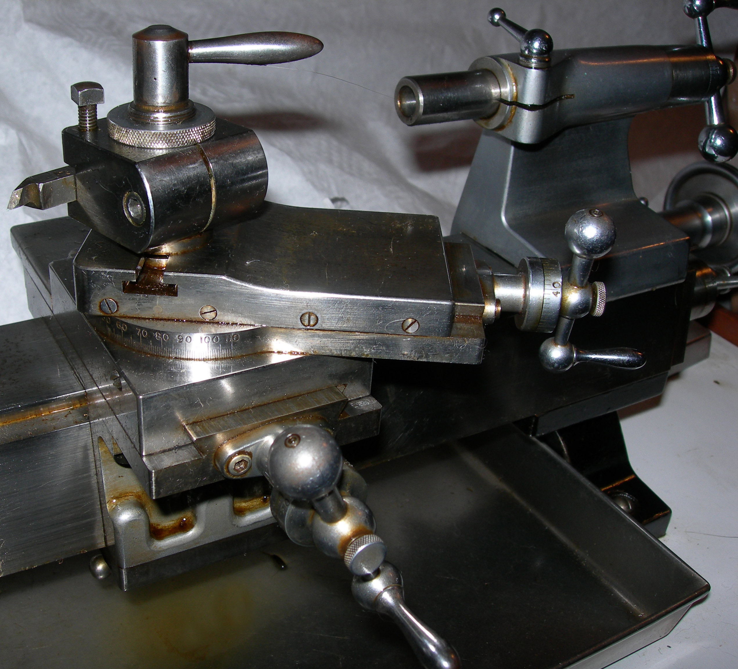
Beautifully proportioned compound slide rest in polished steel
|
|
|
|
|
|
|
 |
|
|
|
|
|
|
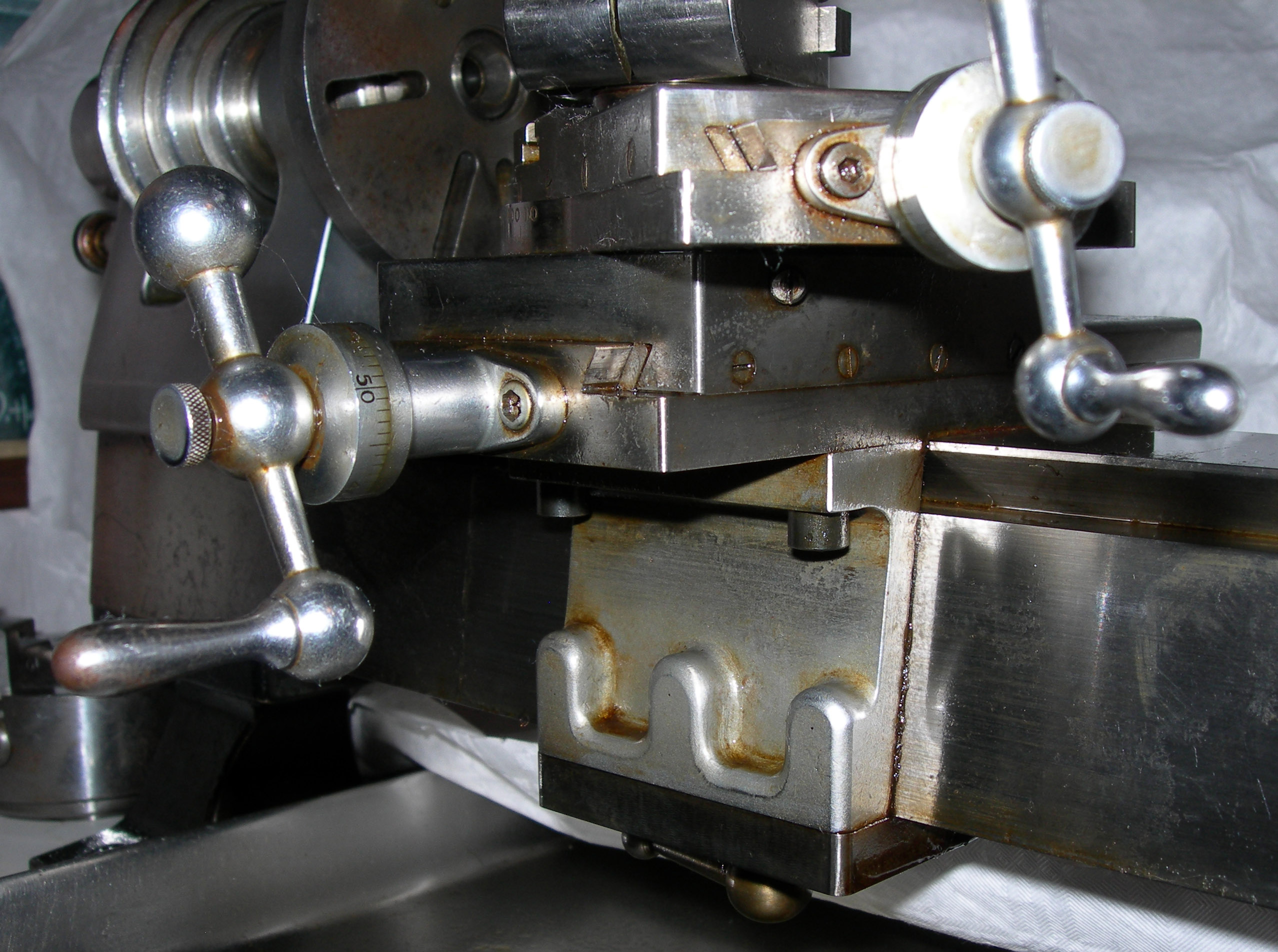
The front apron was duplicated at the back with both having full contact with the entire depth of the bed faces - a design feature also used on the later Japanese Toyo ML1. This system provided an unusually large contact area for a miniature lathe
|
|
|
|
|
|
|
|
|
|
|
|
 |
|
|
|
|
|
|
Every edge perfectly radiused …...
|
|
|
|
|
|
|
 |
|
|
|
|
|
The scale of the handles is clear from this macro photograph
|
|
|
|
|
|
|
|
|
|
|
|
 |
|
|
|
|
|
|
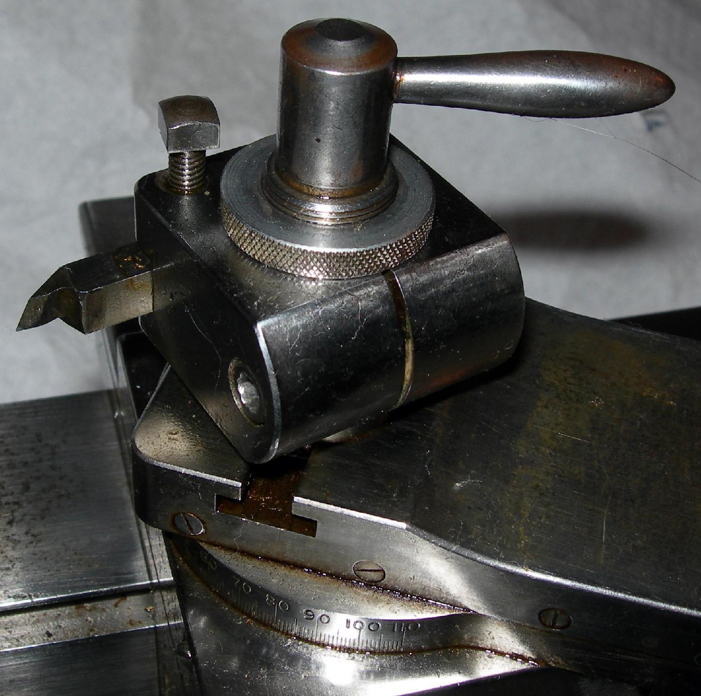
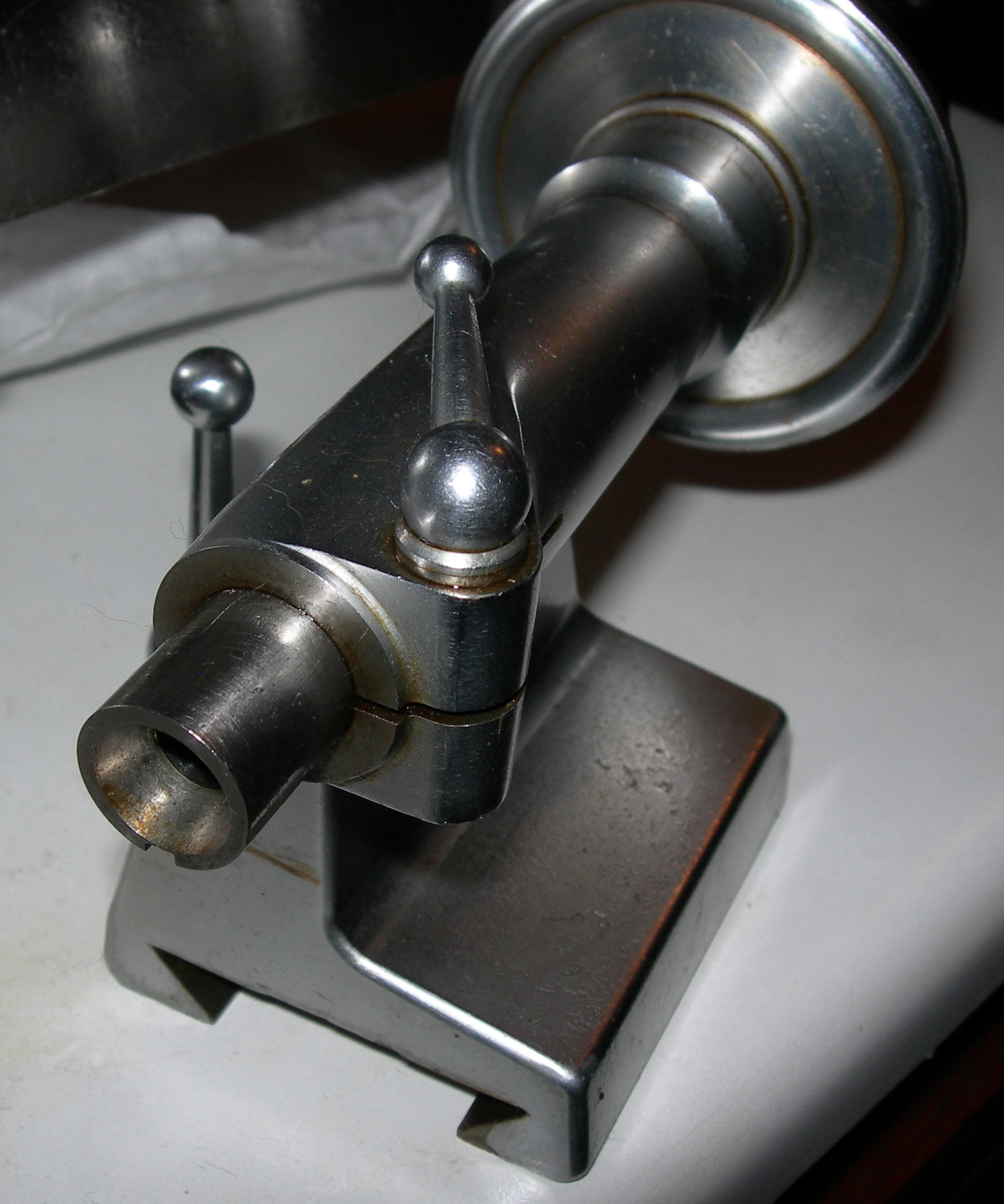
A form of "Norman Patent" toolpost was used, (identical in concept to that used for many years on the post-1924 Drummond M-Type) but much improved by Mr. Hudson. Like the ordinary "Norman" it could be both quickly altered in height and swivelled around its mounting boss - but with the added sophistication that the whole unit was self contained and could be instantly released and slid out of its T-slot holder. Releasing the lock-down handle enabled four coil springs to lift the assembly, the height setting then being finely adjustable by knurled ring at the top.
|
|
|
|
|
|
|
|
|
|
|
|
|
|
|
 |
|
|
|
|
 |
|
|
|
|
 |
|
|
|
|
 |
|
|
|
|
|
|
|
|
|
 |
|
|
|
|
|
|
|
|
|
 |
|
|
|
|
|
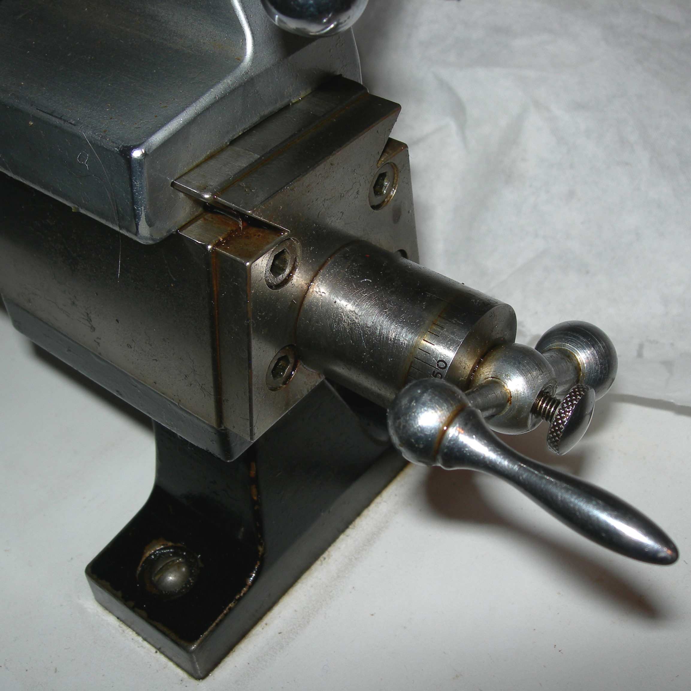
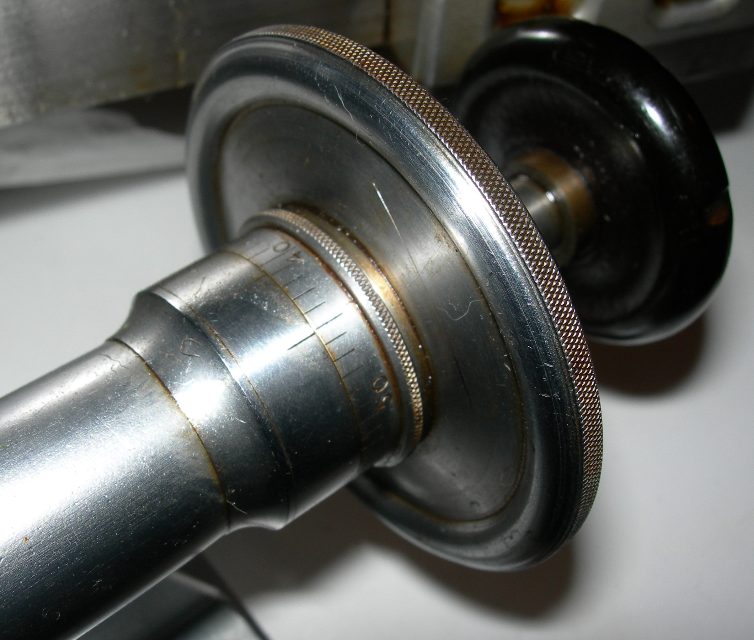
Micrometer dial and large handwheel of collet tailstock
|
|
|
|
|
|
|
 |
|
|
|
|
|
Sitting inside the tiny black dot circled at the top of the sheet is the minute bush made using the lathe
|
|
|
|
|
|
|
|
|
|
|
|
|
|