 |
|
|
|
|
|
|
|
|
|
|
|
|
|
|
|
|
|
|
|
|
|
|
|
|
|
|
|
|
|
|
|
|
|
|
|
|
|
|
|
|
|
|
|
|
|
|
|
|
|
|
|
|
|
|
email: tony@lathes.co.uk
Home Machine Tool Archive Machine-tools Sale & Wanted
Machine Tool Manuals Catalogues Belts Books Accessories
LeBlond "Dual Drive" Lathe
Handbooks & Parts Lists are available for the Mk. 1 Dual Drive
and the Mk. 2 Dual Drive
Regal lathes 1930s to 1944 Regal lathes 1944 to late 1950s
Regal lathes late 1950s onwards LeBlond Dual Drive
Regal home page LeBlond home page Regal 10-inch photographs
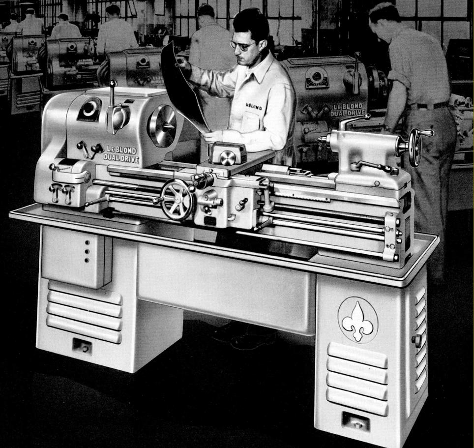
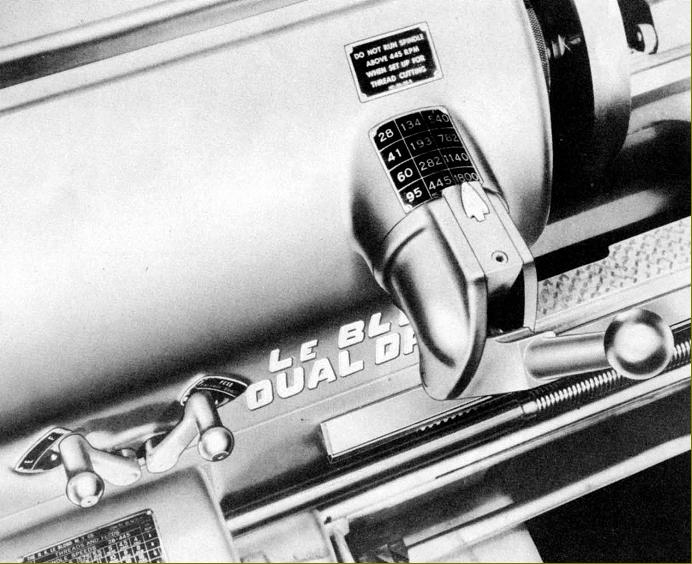
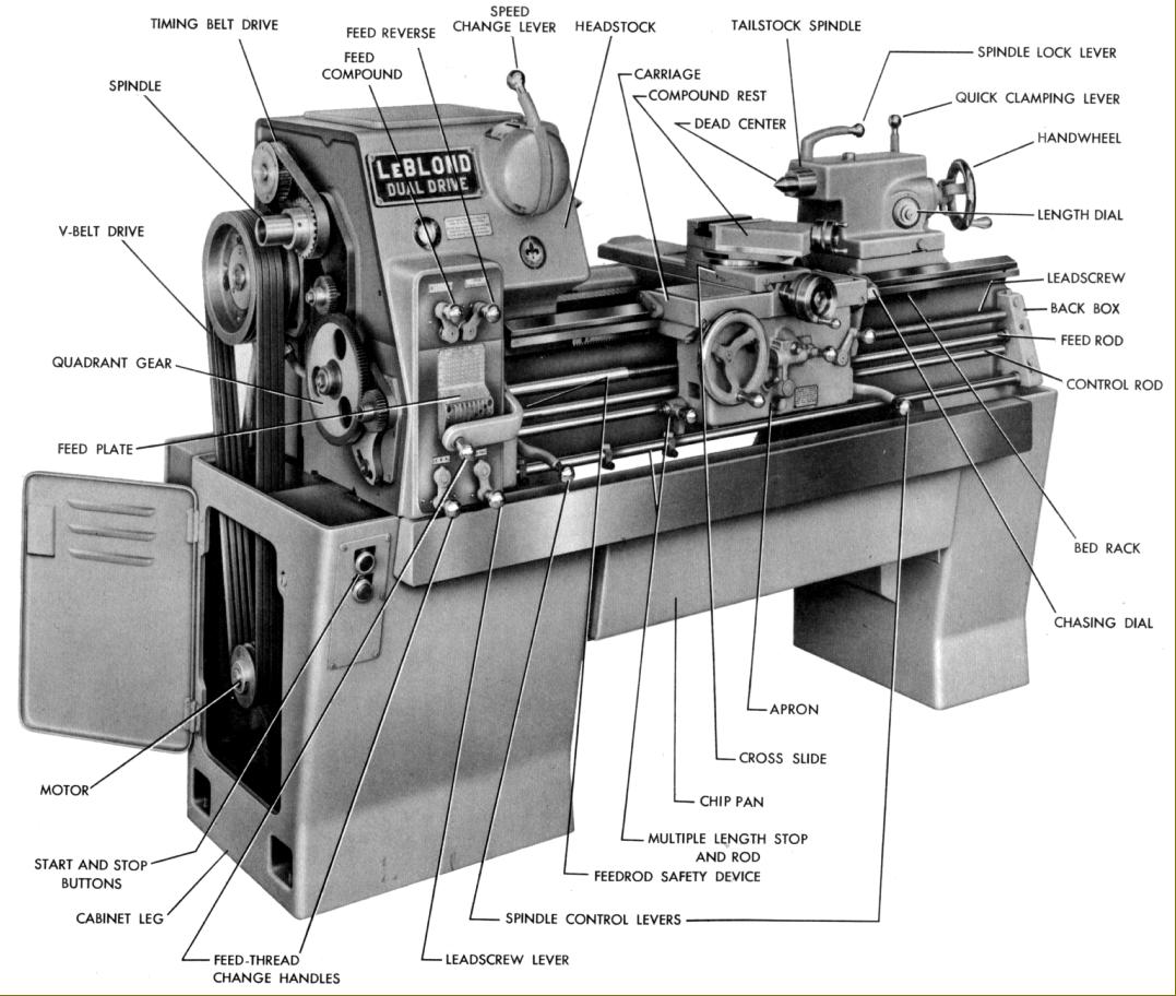
Introduced in 1946, the 15-inch swing by 30-inch between centres LeBlond "Dual Drive" was to be built in Mk. 1 and Mk. 2 versions in attempt to provide a versatile lathe for "training, maintenance, experimental workshops and light production duties". The main feature of this heavy, 2450 lb lathe was a headstock of mechanical complexity with two separate drive systems powered from a single, 1800 r.p.m 3 h.p. motor mounted on a pivoting plate underneath the headstock. A quiet-running high-speed range (540, 782, 1140 and 1800 r.p.m.) was provided by direct drive through four V-belts and low and intermediate speeds (28, 41, 60, 95, 134, 193, 282 and 445 r.p.m.) by a fully-geared drive where greater torque was required for such tasks as turning large diameters or achieving higher-than-usual rates of metal removal. The Dual Drive was mounted as standard on separate heavy-gauge sheet-steel plinths under headstock and tailstock with a chip tray incorporating a deep central swarf pan. Doors in both end faces of the stand gave access to the motor compartment beneath the headstock with a storage compartment built into the other end.
Continued below:
|
|
|
|
|
|
|
|
|
|
|
|
|
 |
|
|
|
|
Mk. 1 LeBlond Regal Dual Drive - its rounded styling typical of lathe design until the 1950s
Continued:
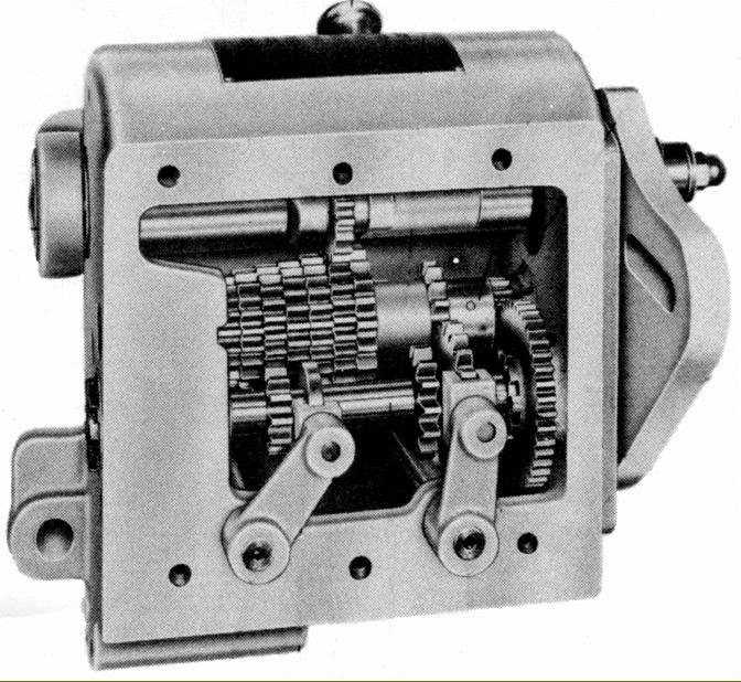
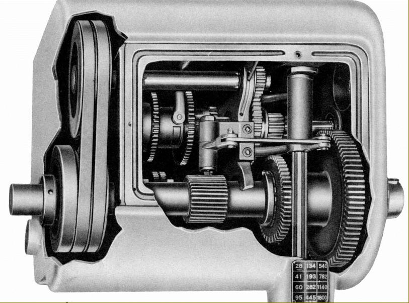
Of typically LeBlond design, the headstock, was heavily built with hardened and ground alloy-steel gears running on drive shafts that were all, with the exception of the bronze-bushed feed from spindle to changewheels, supported in ball or roller bearings. The No. 4 Morse taper headstock spindle was bored through 1.5-inches, ran in taper-roller bearings and - surprisingly in view of the lathe's strength and capacity - was fitted with only the smallest of the American long-key taper-nose fittings - an L00. Instead of a simple splash lubrication system the headstock was provided with an automatic forced feed from a pump - though this worked only when the spindle was going forwards; if used in reverse for any length of time the makers advised running forwards occasionally to feed oil to gears and bearings or, if used continuously in reverse, to take out the unidirectional pump and replace it at 90-degrees to its normal position. With great ingenuity the designers had arranged not only for one control lever to select the 12 speeds (by rotation and though a hinge that provided an axial movement) but also for the carriage feed rate to be slowed automatically when a change was made from slow-speed gear to high-speed belt drive. Although the 4-step V-belt drive pulleys on motor and input shaft were entirely conventional the final drive (for the high-speed) was by twin V-belts running on pulleys a fixed distance apart with no means of adjusting the belt tension. Because the makers must have rejected the idea of using "link-belts", the lower pulley had to be made adjustable: this was achieved by producing a large hub with its right-hand flange formed as the outer section of one V-pulley. Keyed to the hub, and adjustable along it, was a central ring machined so that each side formed one half of a V groove; to complete the assembly a second ring, again machined with half a V groove, was screwed to the outer part of the hub. By adjusting the position of the central and outer rings (by means of a screw-on boss) the effective width of the V-grooves could be narrowed or widened and hence the belts moved slightly inwards or outwards to adjust the tension. On lathes with serial numbers 2 to 225 and 227 to 272 inclusive the drive to the spindle incorporated a combined multi-plate clutch and brake unit mounted outboard of the 4-step headstock drive pulley whilst all the others should be found fitted with a self-adjusting and maintenance free electrically-operated brake. The electrical control of the spindle (start, stop, reverse and brake) was by a "third-rod" system with two control levers, one on the screwcutting gearbox and the other on the right-hand face of the apron.
Continued below:
|
|
|
|
|
|
|
 |
|
|
|
|
|
|
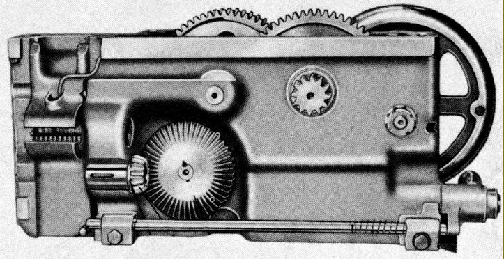
Inside the Dual-drive's screwcutting gearbox
|
|
|
|
|
|
|
|
Continued:
After the complications of the drive system and headstock the rest of the lathe was refreshingly straightforward, though, at the same time, well up to contemporary standards of design. The bed was enormously strong, 11-inches wide and 9.75-inches deep and could be ordered in length increments of 12-inches (though in catalogues the lathe appears only as a 30-inch between centres model). While on early versions the ways for the carriage were machined from the bed material, and of conventional, symmetrical inverted-V and flat pattern, later machines used separate hardened steel ways with that at the front in a form LeBlond termed "compensated" - that is, an extra-wide, shallow-angle outer surface (to better absorb wear) and an inner surface set at a much steeper inclination to take tool thrust. The design of the carriage followed ideal principles: a saddle with long, equal-length, symmetrical positioned wings that allowed the cross slide to positioned exactly on its centre line--and so receive the best possible support. The arrangement was possible because the bed ways ran on past the front and back faces of the headstock so allowing the saddle to overlap it and bring the cutting tool right up to the spindle nose. Formed from a one-piece casting with double walls the apron held a supply of oil in its base distributed by a hand-operated plunger pump to the apron bearings and gears, the cross slide ways and bed. Power sliding and surfacing feeds were arranged in a manner similar to that employed on the larger of the early Regal lathes with instant, easy and fool-proof selection, engagement and (more importantly) release no matter how heavy the cut. A separate slotted power rod, driven by a multi-face dog clutch on the output from the screwcutting gearbox and fitted with the usual LeBlond design of safety-overload, spring-loaded, automatically re-setting ball-bearing clutch, ran through an apron-mounted pinion and drove it through a sliding key. The pinion drove, in turn, a crown wheel and then (through a toothed "face clutch" and a sliding selector gear controlled by a single handle on the face of the apron), the power feeds. A separate lever, emerging from the apron's right-hand face, was used to clutch the feeds in and out. Unlike the heavier LeBlond lathes the carriage feed could not be reversed from the apron instead the usual headstock-mounted lever was employed working through an internally mounted tumble-reverse mechanism. A useful device fitted to all Dual-Drives was a multiple automatic length stop. This consisted of a long bar below the feed-rod fitted with three adjustable stops (though more could be added) that stopped the carriage drive by releasing the feed-rod's dog clutch. To re-start the drive it was only necessary to lift the trip lever handle when a spring snapped the bar to the right and engaged the feed-rod clutch.
Continued below:
|
|
|
|
|
|
|
|
|
|
|
|
 |
|
|
|
|
|
|
Dual Dive headstock interior
Continued:
Fully enclosed, the screwcutting and feeds gearbox was provided with a positive flow of oil from the same pumped supply used by the headstock. The initial 2-speed drive to the box was from a lever on the headstock marked fine and coarse feeds. An 8-position spring-loaded tumbler then selected the main pitches with each having three ratios selectable by a 3-position quadrant lever on the face of the box - thus giving a total of 48 pitches and feeds. The leadscrew was normally left disengaged other than when screwcutting with a 2-position lever, on the face of the box, providing easy selection and disengagement.
With good-sized, zeroing micrometer dials the compound slide rest had taper gib strips adjusted by pusher screws at both front and back. The top slide was clamped down by two T-bolts, with heads held in a circular T-slot machined in the cross slide, and its tool-holding T-slot set at an angle. Unfortunately the cross slide was of the "short" type, a design that guaranteed wear would be concentrated on the front and middle section of its ways. To protect the feed screw the rear of the slide was provided with a cover, a not-unusual fitting but in this case thoughtfully provided with a hingle so that it could be lifted and the screw lubricated. Suitably massive, the tailstock on the Mk. 1 held a No. 3 Morse taper centre and was of the set-over type to allow the turning of slight tapers. The single bed-clamp nut was tightened by that nightmare of piece-rate workers, a loose, self-hiding spanner. On the Mk. 2 Dual Drive some improvements were made with the handwheel set at an angle, an unusually positioned spindle-travel dial built into the front face and a captive handle that clamped the unit to the bed using an eccentric shaft.
Although a finely engineered piece of work, in true LeBlond fashion, and with easy-to-use controls, the headstock of Dual Drive was, perhaps, an unduly complicated affair and the same speed range could have been easily achieved (as it was by many makers) using conventional gearing and a 2-speed electric motor - though perhaps the absence of gear-chatter marks on very fine surface finishes turned with the smooth-running V-belts on the high-speed settings was thought to be worthwhile.
Continued below (Mk. 2):
|
|
|
|
|
|
|
 |
|
|
|
|
|
Rear view of the Dual Drive apron
|
|
|
|
|
|
|
|
|
|
|
|
|
 |
|
|
|
|
|
|
Mk. 1 Spindle-speed controls
|
|
|
|
|
|
|
 |
|
|
|
|
|
LeBlond Dual Drive Mk. 2.
Of almost identical mechanical layout to the Mk. 1, the Mk. 2 Dual Drive was given not only a more modern, angular appearance but also a number of mechanical refinements. These included a completely redesigned tailstock with its handwheel set at an angle, an unusually positioned spindle-travel dial built into the front face and a captive handle that clamped the unit to the bed using an eccentric shaft. To reduce costs, the final belt drive to the headstock by twin V-belts was replaced by a toothed "timing" belt.
|
|
|
|
|
|
|
|
>
|
|
|
|
|
|
|
|