|
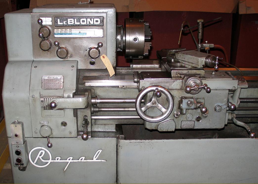
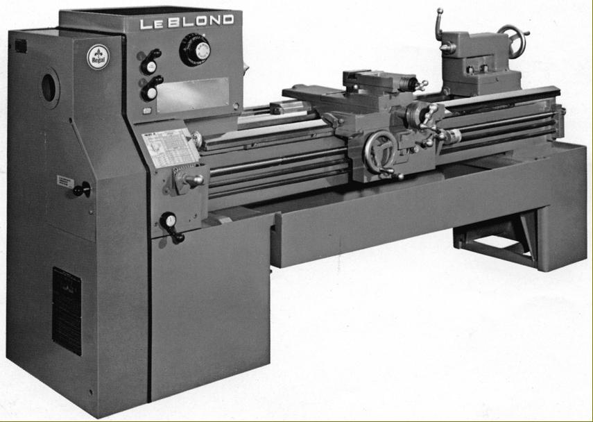
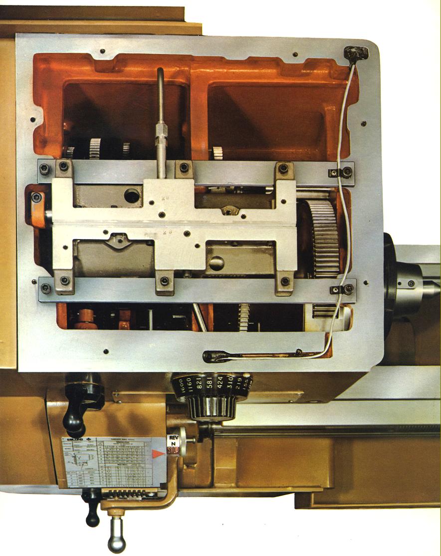
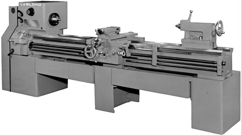
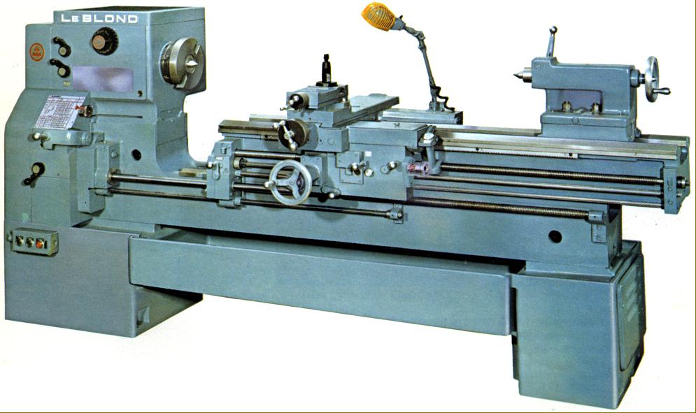
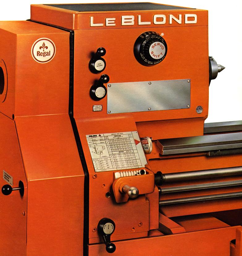
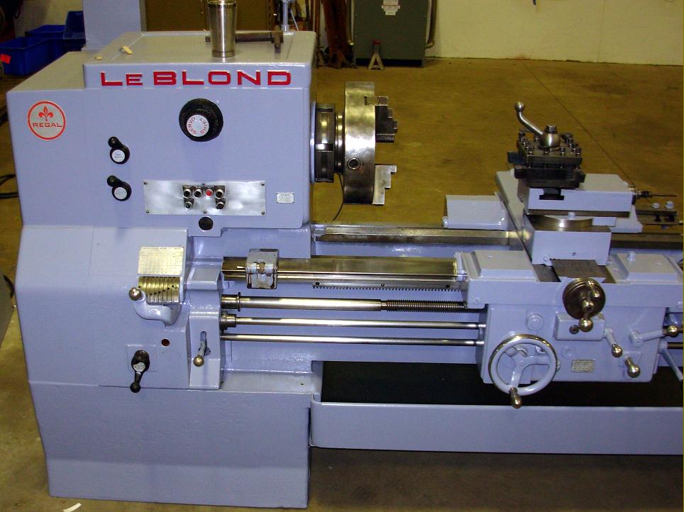
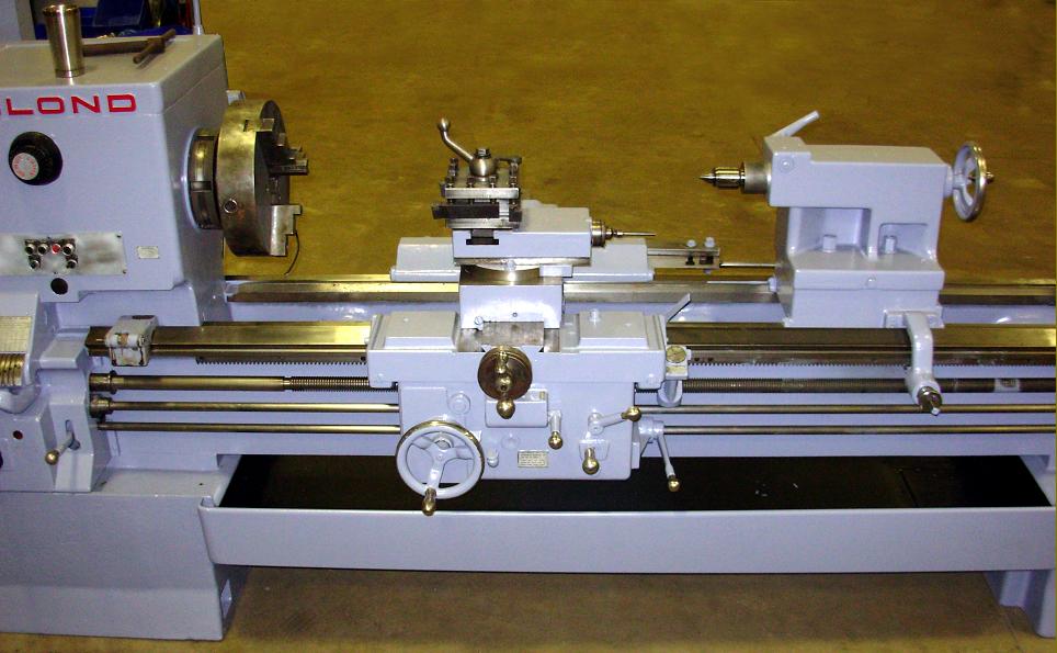
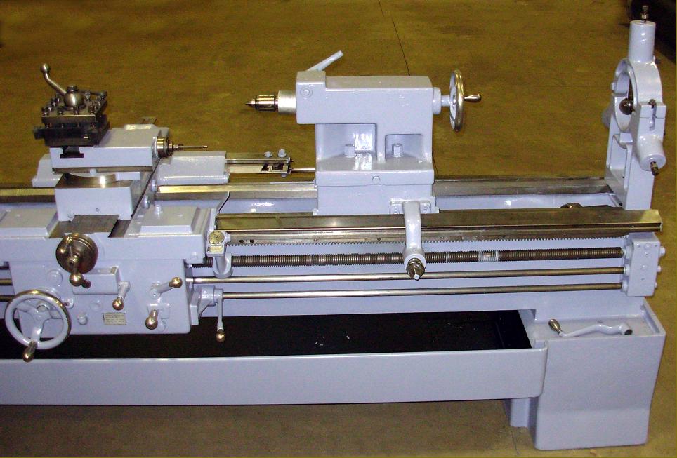
Although late-model LeBlond Regal lathes all shared the same basic design (regardless of capacity), there were two types of headstock spindle-speed selection: a standard type with four levers and a "Servo-shift" model with speeds pre-selected and changed automatically by hydraulics. The ordinary model can be recognised by its 4-lever control and the Servo model by the use of two levers and a speed-selector dial.
Known both as the LeBlond and LeBlond MAKINO, several versions were offered (the letter and digit in the bracket was included in the Serial Number): 13" (C3); 15" (C5); HC 15" Dual-drive Model; 17" (E3); 19" (E7); 21" (F7) and the massive 24" (3H).
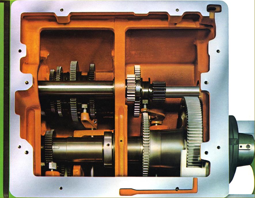
Unfortunately, the Servo-shift headstock proved to be a mistake; to be kind it was a good idea that failed in its execution (and one that other American makers of quality lathes - LeBlond, Monarch and Lodge & Shipley - also tried to employ). The aim, though laudable (to speed up and semi-automate the otherwise slow and ponderous speed change on a large-lathe headstock), failed in the manner of its execution. The method employed - what in the USA is often called a Rube Goldberg* lash-up - utilized solenoids, stepper switches and custom-built hydraulic actuators and fluidic devices. The system, which used a standard but modified headstock casting, was supposed to have worked in the following way: the lathe operator turned a speed-selector dial to pre-select the required spindle speed from the 36 or so that were available. Having pre-selected the speed, the operator pushed a button marked "shift" and stood back and let the "Servo Shift" mechanism (driven by a continuously-running electric motor of various ratings) do the rest - an amber lamp on the lathe's control board lighting up to indicate "shifting in progress". Concurrently, the system used solenoids that "stacked up", a set of shims and forced them into fingers to determine which gears were to be shifted and where; this movement caused the fluidics to pulse hydraulic cylinders within the headstock and so slide gears backwards and forwards along the splined shafts trying to get them into mesh. Simultaneously, in imitation of a human operator pulling a chuck back and forth to line up the gear teeth, another fluidic device was "jogging" the spindle through perhaps 120 degrees of rotation. Because the pre-selector switch had already lined up contact fingers for the micro-switches on the correct gearing, when the mesh was complete (the gearing could be heard banging away as it attempted to do this) the switches made contact and a green indicator lamp marked Shift Complete lit up on the control board. With engagement complete another set of contacts was closed that enabled the main spindle drive motor to be started. Now, if all aspects this mechanism were in synchronisation the gears were correctly shifted and the lathe was ready to restart on its new speed but, if things were not correctly arranged, the either lathe started "between" gears - gnashing some teeth in the process - or ran at the wrong speed. The selection performance over (and success or otherwise accomplished) the operator could then start the main spindle drive motor in whatever direction was needed and wait for it to run up to full speed; when this was accomplished he could then engage the drive to the headstock through a "Warner" electromagnetic combined clutch/brake unit located inside the hub of the V-belt drive pulley on the headstock input shaft. Because the lathe was designed to carry massively heavy loads (that took time to accelerate up to speed), LeBlond wisely provided a means (located in a large rear-mounted control box) of both controlling how quickly the clutch engaged and also programming acceleration and braking to suit the mass of a particular job.
*"Rube Goldberg" is not an ethnic slur, but a reference to a (long-deceased) cartoonist Rube Goldberg who drew fantasy cartoons of unusually complex mechanisms undertaking the simplest of tasks. His mechanisms incorporated household items, animals, candle flames linked by arrangements of open belts, chain drives, gearing and linkages. For this reason when older people refer to something as a "Rube Goldberg" it is a reference to something unnecessarily complex..
|
|