|
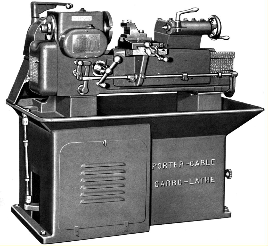
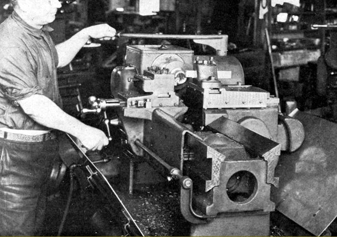
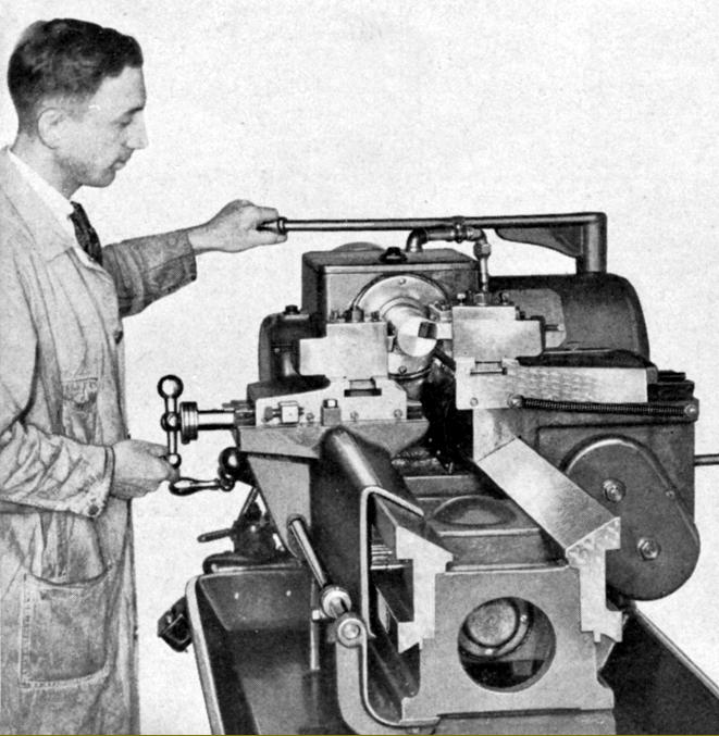
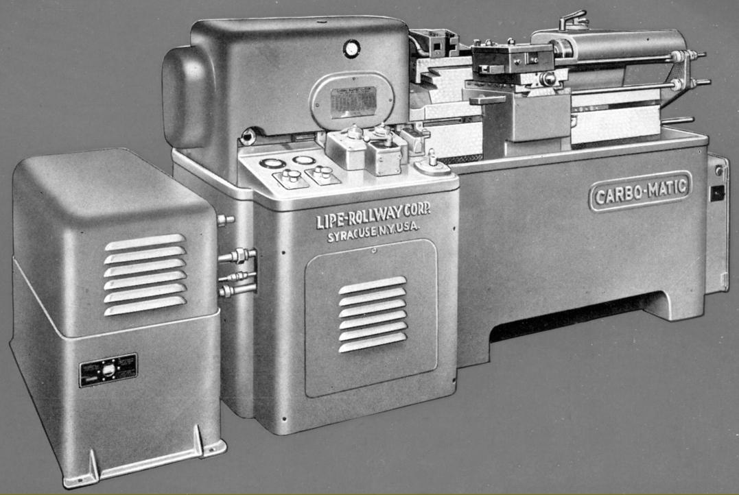
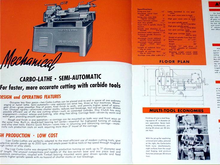
Believed to have been introduced in 1932 - eighteen years after production started of their original High-speed Production Lathe - the 7" x 18" Carbo-lathe was Porter-Cable's answer to the need for greater capacity, higher speeds, increased rates of metal removal and an up-to-date, built-in drive system. Its name, "Carbo", referred to the machine's ability to make use of the recently introduced carbide-tipped tooling, a development that allowed significant improvements to be made in turning performance
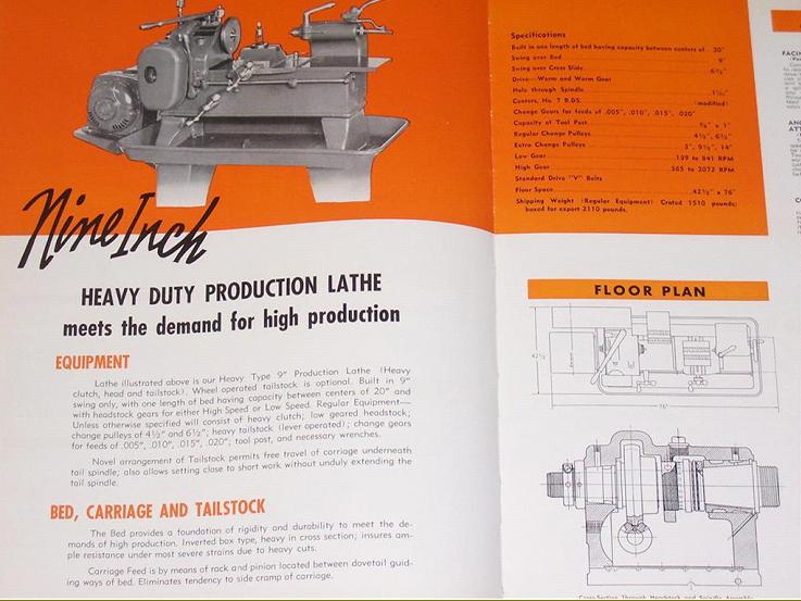
Because the original machine was still available, the new model was described in some of the Company's literature as the Super Carbo-Lathe and, although it had the same layout and bore a close resemblance to the earlier version and worked in the same way, it was enormously strengthened and altered in many ways - with a quite different design of bed and the weight almost doubled to 2000 lbs. To reduce friction losses in the transmission a total of 18 roller or ball races was used throughout the lathe. Like its predecessor it was, in comparison to a full-blown capstan or turret lathe, an uncomplicated and relatively inexpensive machine, intended for a niche market and designed to machine simple jobs that would be produced non-stop for several months - though more complex tasks could be broken down into stages with several machines, installed alongside each other, tooled to perform one operation after another.
Made from a chrome-nickel iron, the bed and headstock were cast as one, weighed 600 lbs and carried mirror-image ways at the top and on the front and back faces of the bed. The top ways sloped steeply inwards (in a V-formation giving some extra clearance beneath the spindle line) with a vertical outside surface and below, separated by a sunken rectangular section, a second pair of V-ways to guide the lower edge of the carriage. As before, the rear slide carried the tailstock with that at the front responsible for the carriage (the latter arrangement resembling the design used by Rivett on the 8-inch Precision and 608 toolroom lathes).
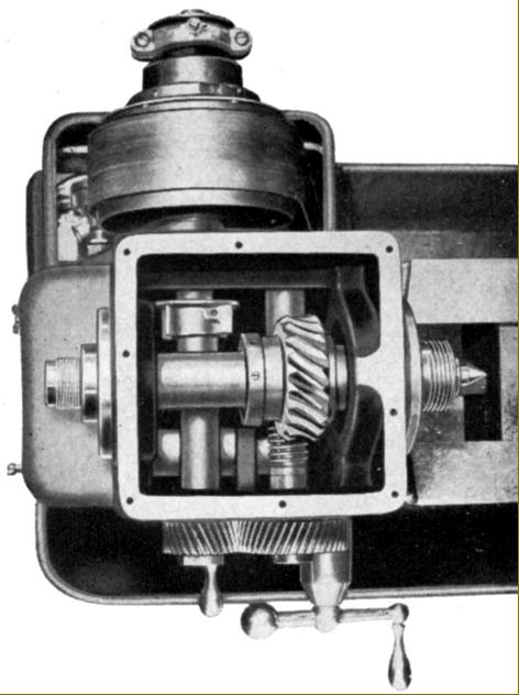
With a bore of 17/16", a massive No. 5 Morse taper socket (sleeved down to 3 Morse) and a 2.75" x 6 t.p.i. thread, the 0.5 nickel chrome steel spindle ran in Timken taper roller bearings and was powered by a motor of up to 10 h.p. AC, or 7.5 h.p. DC, held on an adjustable plate in the left-hand compartment of the cast-iron stand. Four V-belts took the drive up the rear of the machine - an externally mounted turnbuckle being used to set the belt tension - with, at the top, a disc clutch connected to a transverse shaft that passed beneath the spindle and then, via a pair of 1.75-inch wide pick-off gears (under a cover on the headstock's front face), to a second shaft, parallel to the first that turned the spindle through worm-and-wheel gearing. A choice of two ratios was offered: a lower of 3.5 : 1 that gave spindle speeds from 95 to 1130 r.p.m. and a higher of 2:1 that provided 170 to 2000 r.p.m. An oil bath was used to lubricate the headstock internals with a simple oil slinger, fastened to the input (clutch) shaft, distributing the lubricant to the worm, worm wheel and spindle bearings.
Carriage feeds were provided (cheaply but rather inconveniently) by three pick-off gears under a cover at the headstock end of the lathe - the rates of travel per revolution of the spindle being 0.005", 0.01", 0.015", 0.02", 0.025" and 0.03". The feed gearing from the headstock was arranged so that the drive was taken by worm-and-wheel gearing from the lover headstock cross shaft, this reduction allowing the first pick-off gear to rotate at 100 r.p.m. when the spindle was turning at 1000 r.p.m. The lowest pick-off gear turned a clutched shaft (with handwheel attachment) that extended the length of the bed and drove an enclosed, oil-bath lubricated, 10 : 1 ratio worm-and-wheel gear assembly bolted to the inside face of the carriage. The worm wheel (the larger gear) was connected to vertical shaft that carried on its upper end a pinion gear that engaged a rack fastened to the inside of the saddle. Along the front of the bed was a bar, arranged to provide a pre-set disengage to the power feed with a linkage connecting it to the dog clutch fitted to the powershaft at its headstock end.
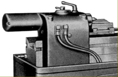
Equipped with a 1.75-inch diameter, No. 3 Morse taper barrel having 4 inches of travel under lever control and 3.5 inches by screw feed, the tailstock was very heavily built with 8.5" of bearing surface against the bed.
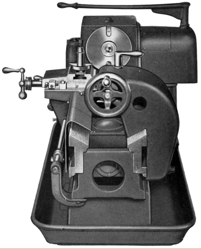
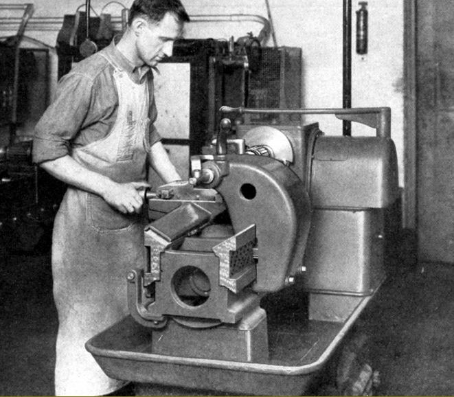
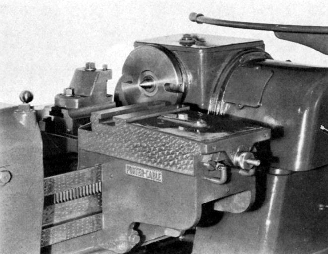
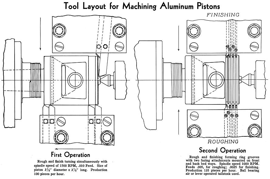
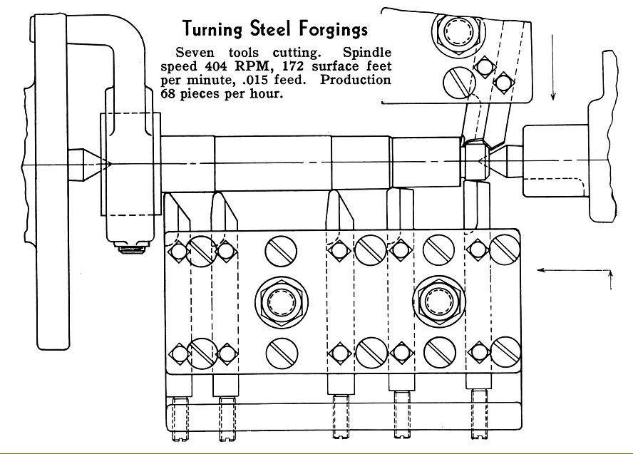
A number of standard accessories were offered including: a rear-mounted, 8-inch wide facing (cut-off) slide that could be adjusted over a range of 2 inches and with 2 inches of slide travel; an angular facing attachment - similar to the standard unit but with the cross slide able to be swivelled through an arc of 180°; a taper-turning attachment; a special, extra heavy-duty tailstock with a built-in ball-bearing centre and available with screw, lever or pneumatic operation; collets with closure by either an ordinary screw wheel or quick-action lever and a number of different toolposts in including an American style of rocker post, a clog-heel open type, a full-length "gang" holder that could be set up with multiple tools and an ordinary 4-way type.
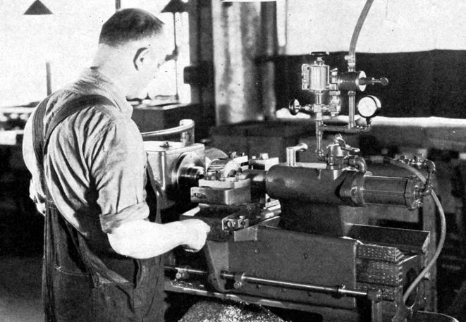
At some point in the mid 1930s Porter-Cable introduced a hydraulically driven Carbo lathe but, as no details are currently available, it is pure assumption to conclude that the expensive worm-and-wheel gearbox and rack drive to the saddle was replaced by a cheap hydraulic cylinder.
Having sold their Lathe Division in 1937 to W.C.Lipe, Porter cable concentrated their efforts on the power-tool market..
|
|