 |
|
|
|
|
|
|
|
|
|
|
|
|
|
|
|
|
|
|
|
|
|
|
|
|
|
|
|
|
|
|
|
|
|
|
|
|
|
|
|
|
|
|
|
|
|
|
|
|
|
|
|
|
|
|
|
|
|
|
|
|
|
|
|
|
|
|
|
|
|
|
|
|
|
|
|
|
|
|
|
|
|
|
|
|
|
|
|
|
|
|
|
|
|
|
|
|
|
|
|
|
|
|
|
|
|
|
|
|
|
|
|
|
|
|
|
|
|
|
|
|
|
|
|
|
|
|
|
|
|
|
|
|
|
|
|
|
|
|
|
|
|
|
|
|
|
|
|
|
|
|
|
|
|
|
|
|
|
|
|
|
|
|
|
|
|
|
|
|
|
|
|
|
|
|
|
|
|
|
|
|
|
|
|
|
|
|
|
|
Early Rivett 8" Precision lathe.
Was this beautifully-finished 8-inch Precision Lathe, as the makers proudly boasted in their literature, "The most complete tool of its kind ever conceived." ? Despite the fact that at the time the use of excessive hyperbole in advertisements was common, this was indeed a lathe that came as close as possible to the ideal in its class. Thoroughly well-thought-out as a design and made from the finest-quality materials, it was manufactured to a standard of fit and finish that even the passage of many decades cannot fail to disguise.
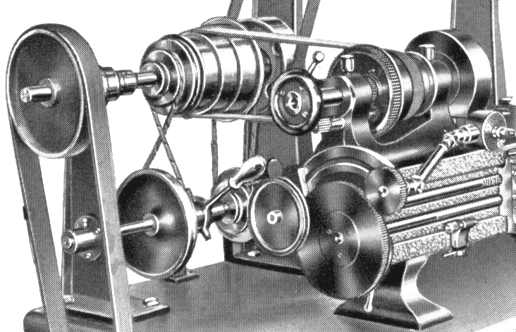
Edward Rivett had a long background in the watch tool industry before he turned his hand to manufacturing larger machines. From 1884 he was the General Manager of The Faneuil Watch Tool Company of Boston and expanded the factory's product range to include precision grinders and more profitable lines of larger bench lathes, including the No. 3 and No. 4. By the late 1890s he had designed, and was producing, the 8" Precision, which used the headstock and tailstock of the earlier No. 4 plain-turning precision bench lathe, but with a completely different bed 40-inches long, of cast-iron, profile milled and with a hand-scraped finished on all faces. The distance between centres, was 22 inches and the swing 81/2 inches. The (initially) unusual arrangement of having the smallest headstock pulley by the front bearing (instead of the other way round as is still common) meant that not only could the bearing could be much larger than normal for a lathe of the same centre height - but it was also surrounded by a greater mass of supporting metal.
Both spindle bearings had outer surfaces which were cylindrical in section - and could be continuously adjusted for wear whilst preserving their central alignment. The front bearing was 21/2" inches in diameter and both were 23/8"-long. Until about 1910, a now hard-to-find 4OS collet was used, later models employed the 4NS - and the last versions a 5C.
The maker's description of the spindle and its bearings is worth considering: " ….. of the best tool steel, and like the spindles are made as hard as fire and mercury will make them, and then ground with diamond to a perfect fit." I suppose that says it all, really ……
If the headstock bearings were particularly well made, then the design and construction of the bed and carriage was even more impressive for, instead of sliding just on the top surface of the bed, and being located by keeper plates front and rear, on the Rivett 8" Precision almost the entire front face of the lathe bed was brought into play as part of the saddle-bearing surface to produce a bedding area of 74 square inches, a figure which it is believed has never since been surpassed on any lathe of comparable size Most lathes use only the top face, and upper edges of their beds to guide the saddle, but on the Rivett the front face of the bed, formed into dovetails and plain ways, was used to support the apron as well. This resulted in a very stiff structure beneath the cutting tool and a saddle-to-bed bearing area of 74 square inches (the rare English Spencer lathe had a similar but inferior system - and the little Toyo precision lathe of the 1960/70s rejoiced in twin aprons guided by both front and rear bed faces).
Fortunately, most examples of the lathe carried a maker's plate on the front of the apron complete with patent dates: May 17th 1887, November 10th 1891 and August 27 1895. However, these are not always a reliable indicator of production schedules and were often applied for some years before being granted: neither were they were they always strictly connected with the machine to which they were applied, often being used as a form of self-advertising - though in the case of Rivett's superb products this would have been entirely justified. If any reader has an 8-inch Precision, or a variation of the lathe with different dates on the plate, the writer would be interested in hearing from them.
Continued below:
|
|
|
|
|
|
|
 |
|
|
|
|
|
|
Continued:
The leadscrew, having been cut from, "one of the best master screws in the country.", was used only for generating threads, a separate power shaft being fitted to operate the power longitudinal and cross feeds. The power sliding, that is, along the bed, was operated through a "friction gear", able to be engaged and disengaged by a lever on the apron. A useful automatic disengage was also fitted to this feed, its trip stop being adjustable along the bed. Later 608s included a micrometer adjustment in the apron part of the stop, which allowed the machining of shoulders to within finely set limits.
An unusual extra, invented by Mr Rivett himself and which could only be fitted at the works for $50 before delivery of a lathe, was a device to compensate for temperature variations in the length of the leadscrew. No specific details of this compensatory mechanism are known.
As time passed the 8" Precision underwent numerous small changes; improved and enlarged micrometer collars, larger backgears of a different ratio, alterations to the leadscrew quadrant assembly, the option (never advertised) of a modified headstock casting with a single very wide flat-belt come pulley), the introduction of a screwcutting gearbox and changes in design to the apron and its power feed mechanism. The final version of the 8" Precision was the "608 Toolroom Lathe" - and it is this with model, and the watch-making lathes, that the name of Rivett is most closely associated today..
|
|
|
|
|
|
|
|
|
|
|
|
 |
|
|
|
|
|
|
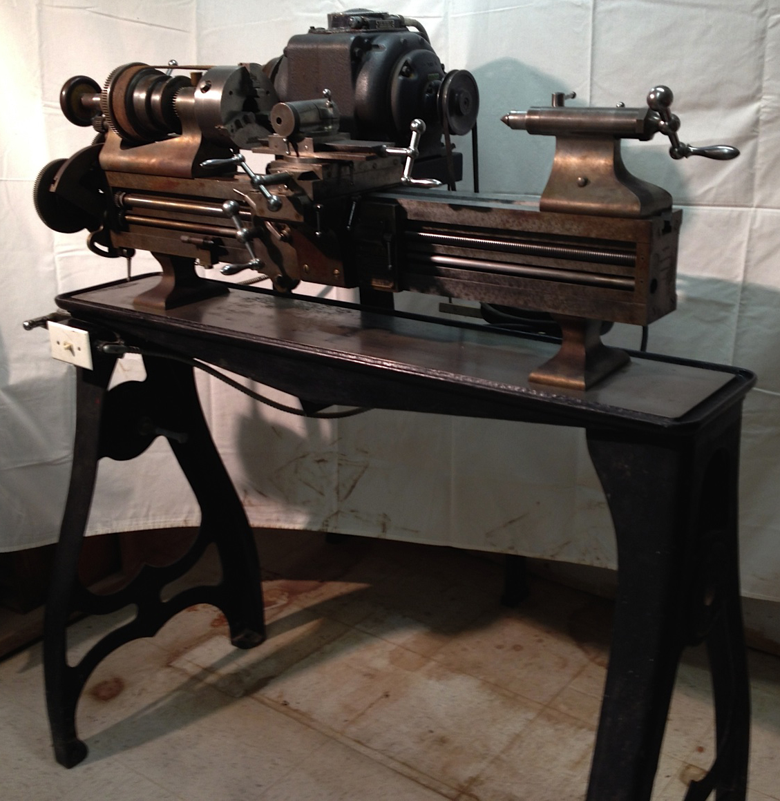
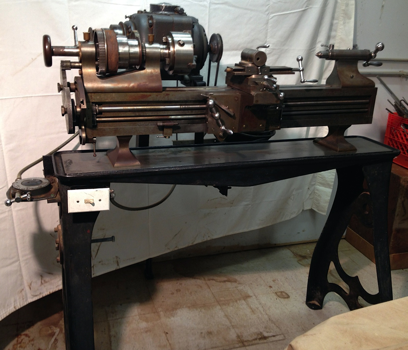
A fine example of a Rivett "8-inch" Precision mounted on a contemporary cast-iron stand. The drive is a non-original but very useful variable speed unit controlled by a remote handwheel mounted on the left-hand end of the lathe
|
|
|
|
|
|
|
 |
|
|
|
 |
|
|
|
|
|
|
|
|
 |
|
|
|
|
 |
|
|
|
|
 |
|
|
|
|
|
|
|
|
|
 |
|
|
|
|
|
|
As advertised in 1914 and 1915 - suitable for the requirements of those using the 608 for experimental and scientific work, the beautifully-presented quartered-oak stand contained a half to three-quarters horse-power motor arranged on a hinged plate. An electrical switch was mounted on the cabinet face and the unit is shown fitted with the optional overhead-drive drum designed to power spindles held in the toolpost or mounted on the lathe bed.
|
|
|
|
|
|
|
|
|
|
 |
|
|
|
|
|
|
Part of the complex countershaft and "overhead" drive system--one of several offered for the lathe
|
|
|
|
|
|
|
 |
|
|
|
|
|
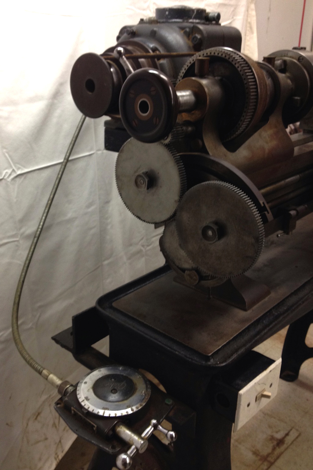
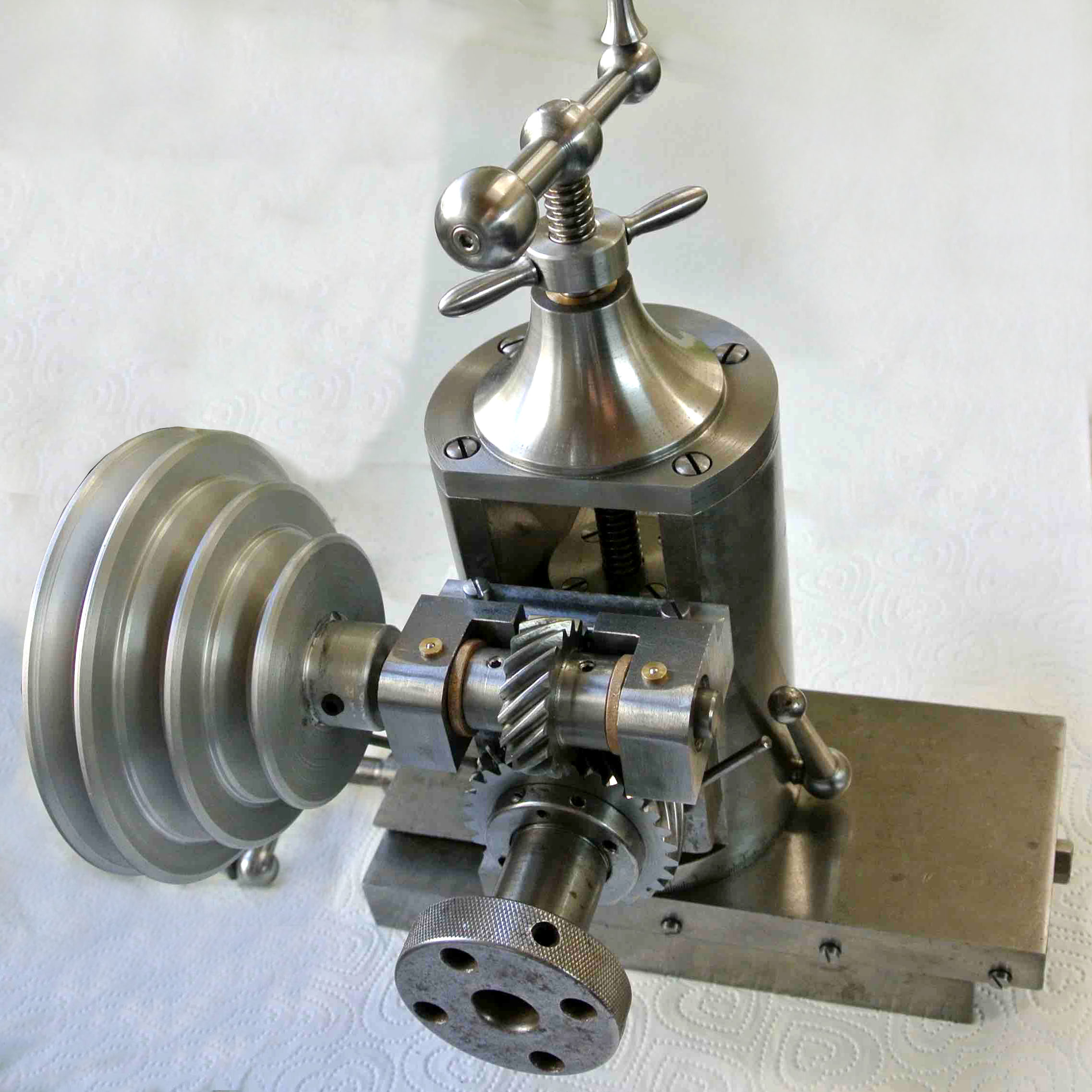
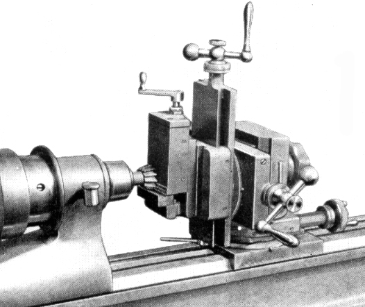
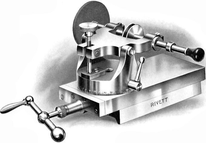
Rivett 8" Precision fitted with a device catalogued as either the "Slide Rest and Milling Attachment" or "Cutter Milling and Gear Cutting Attachment" was a milling slide which included an indexing unit but was of a simpler construction than the "Spiral Attachment and Traverse Miller".
The cross feed travel was 4 inches and the vertical and angular movement 5 inches. Cutters up to a maximum diameter of 3 inches could be manufactured by the attachment, except ball cutters which could be generated in the range of 1/8 inch to 3 inches in diameter.
Index plates were supplied having 45, 56, 60, 64, 72, 80, 84 and 100 indents with others available to special order.
Rivett's advertising emphasised the pride they had in their lathes' ability to generate cutters and claimed that, even though they had milling machines of the very best kind in their workshops, nearly all their special angle cutters were made on either their No.4 or 8-inch precision lathes.
Also visible in this close up is the neat mechanism by which the screwcutting changewheels were driven. A gear, fitted to the left-hand inboard end of the headstock spindle, (and shrouded by the drive pulley) drove a gear and shaft which passed underneath the spindle bearing and emerged to drive a set of changewheels on the double-slotted quadrant arm. Later versions of the lathe offered the option of this mechanism including tumble reverse - but as space was very limited within the headstock belt-pulley, the gears were very small and prone to wear out both themselves and the larger gear that drove them.
|
|
|
|
|
|
|
|
|
|
|
|
 |
|
|
|
|
|
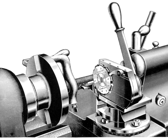
Missing a particular size of large drill ? Why hesitate, fire up your Rivett 608 and make one !
The picture above shows an early Rivett 608 fitted with the "Spiral and Traverse Milling and Grinding Accessory" being used in just such a way. The drive to the milling head was from an overhead drum of the type illustrated on the page showing the bench mounted machine - whilst the indexing unit was powered through the changewheels from an auxiliary belt pulley.
|
|
|
|
|
|
|
 |
|
|
|
|
|
|
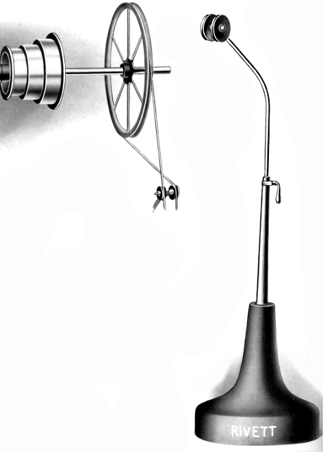
The cutter-carrying worm-driven horizontal spindle could be removed and replaced by the collet-mounted high-speed grinding wheel shown to the left in the illustration above.
|
|
|
|
|
|
|
|
|
|
 |
|
|
|
|
 |
|
|
|
|
|
|
|
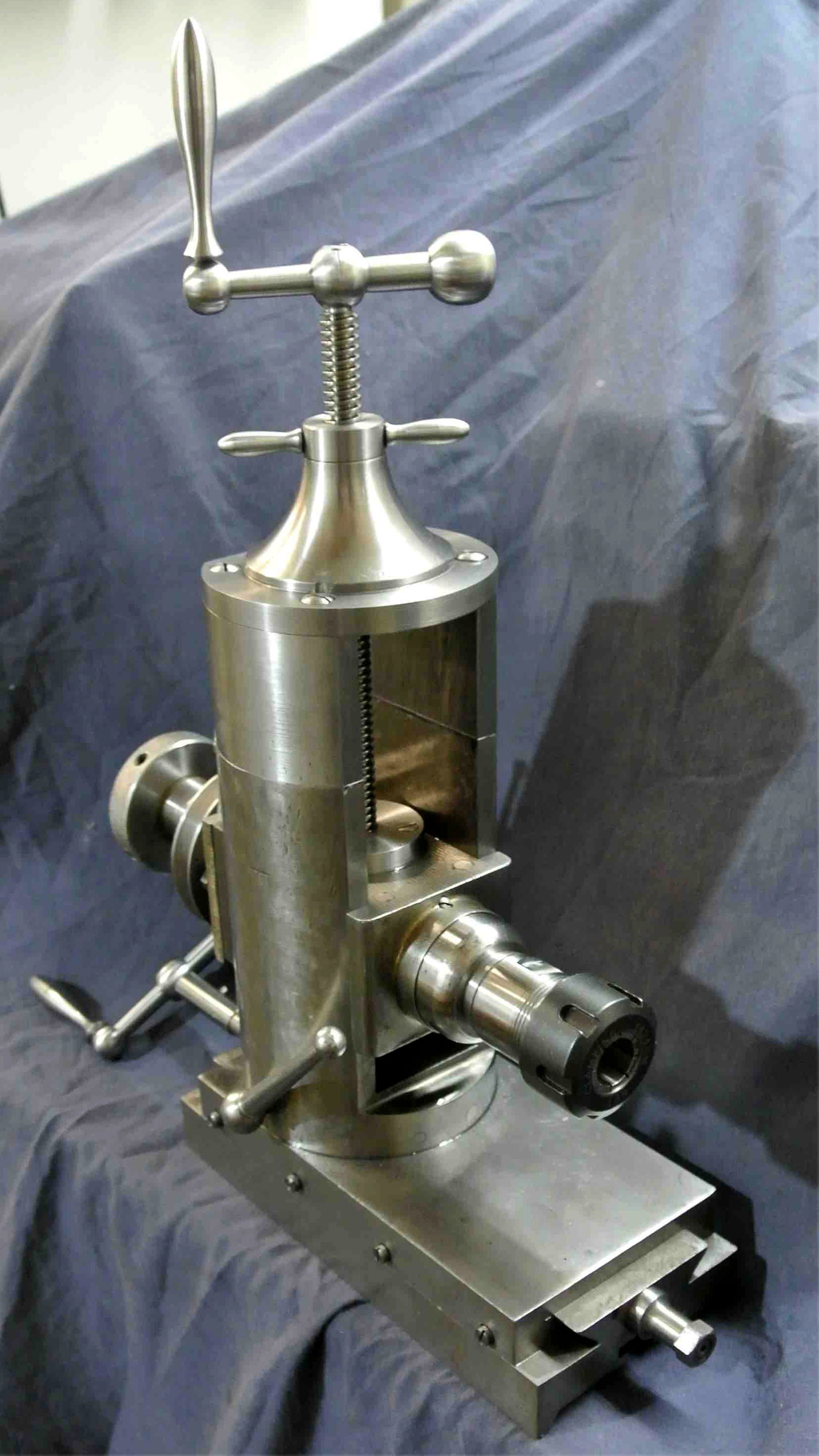
A reader writes: I thought you would be interested to see a rare item I have recently acquired from the USA for my Rivett lathe. Unfortunately, it had various bits bolted to it and the top hat was missing - together with the acme screw and handle. When it arrived the handle for the slide was bent and couldn't be coaxed back to shape with heat and snapped. I made all the missing parts, sourced the absent gears and made two versions that can easily be changed from one to the other with no modifications to the original. One has the original-type gearing - as shown in the catalogue - the other driven directlya scooter 24-Volt DV motor. I made several collet inserts to use an ER25 chuck and two drills and can now mill and drill with it easily.
The original was supplied with either a worm gear or crossed spiral cut gears depending on the speeds required. The spiral cut gears I use give a 1:2 reduction and nicely reduce the motors 2800 r.p.m. by half..
The original machined surfaces throughout were all scraped and very little worn. It had been used without lube for a while and worn the front bevel - so that needed refacing and scraping in. The fit of the glass-hard spindle in the cast iron was perfect and needs a very thin, high-speed spindle oil. Hence, it runs with a very fine film of oil and, even so, the bearing remain oil-tight. I ran it for 15 minutes at 1450 rpm without the bearing getting warm, only about 10 degrees hotter than the surrounding material. The only issue I have is that it's rather restrictive as to making larger-size gear wheels. Ideally, it should be offset towards the chuck so it would cut a disc lined up ahead of the cross slide. Also, the amount it can be moved is rather limited when using larger gear cutters. I have made two riser blocks that that allow me to cut 5-inch diameter wheels. I can easily change back to the original height without modification as I have a spare acme screw the original length.
This Rivett accessory is a joy to have and would love the other attachment that cuts spiral gears, but that's only a pipe dream as I have never seen one except in one photograph.
|
|
|
|
|
|
|
|
|
|
|
 |
|
|
|
|
|
|
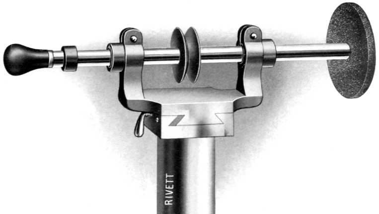
The Spiral Attachment, which screwed onto the headstock spindle and driven by an extension from the changewheels, was designed to work in conjunction with the Traverse Milling Attachment.
|
|
|
|
|
|
|
|
|
|
|
|
|
|
|
 |
|
|
|
|
|
|
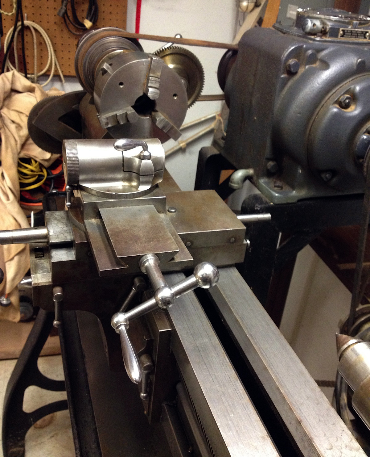
The Rivett Compound Slide Rest was a magnificent piece of work, and so carefully made that only a light touch was needed on the levers to reset any of the angles. In addition, the whole device could be slid off the carriage by slackening just one lever. The eccentric toolholder was especially well designed and enabled the tool height to be instantly set without the use of spanners or packing pieces. To modern eyes this early unit does lack bulk and the micrometer dials were obviously far too small. Later versions were offered with the choice of T slots in the top slide - and the dials were increased in size at least twice.
|
|
|
|
|
|
|
|
|
|
 |
|
|
|
|
|
|
The Rivett Patent "Slide Rest Milling Attachment" was designed to hold and manipulate
work whilst being machined by a cutter held in the headstock spindle. .
|
|
|
|
|
|
|
|
|
|
|
|
|
|
|
 |
|
|
|
|
|
|
The neatly engineered Rivett 608 Taper Turning Attachment for tapers up to 15" in length.
|
|
|
|
|
|
|
 |
|
|
|
|
|
|
The Slotting Attachment carried a sliding head, adjustable for height, mounted on the lathe ways. Although deceptively simple, this device was considered a most useful accessory; a job could be bored and faced, then slotted without losing the critical settings - a risk that was always present in the transfer to a dedicated slotting machine.
|
|
|
|
|
|
|
|
|
|
|
|
|
|
|
 |
|
 |
|
|
|
|
|
|
|
|
|
|
|
|
|
|
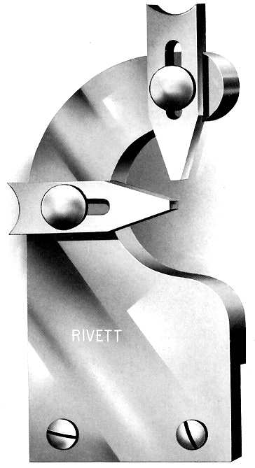
The Rivett "Forming and Cutting-off" slide assembly carried two toolposts, the nearer for holding the robust, circular-section forming tool and the rearmost an inverted tool for parting-off - which is still the best way to do this on any small lathe.
|
|
|
|
|
|
|
|
|
|
 |
|
|
|
|
|
|
"Combination Cutting-Off Attachment" This device carried either an inverted parting-off tool or a knurl.
|
|
|
|
|
|
|
|
|
|
 |
|
|
|
|
|
|
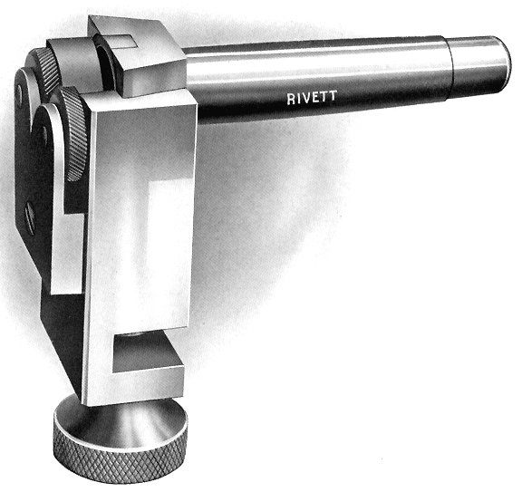
Traditional pattern tip-up tool rest
|
|
|
|
|
|
|
|
|
|
|
|
|
|
|
 |
|
|
|
|
|
|
This grinding attachment was designed to grind gear and other cutters. It mounted on the same base plate as that use by the traditional tip-up tool rest illustrated below.
|
|
|
|
|
|
|
|
|
|
 |
|
|
|
|
Complex milling slide in position on bed
|
|
|
|
|
|
|
 |
|
|
|
|
|
|
Complete high-speed internal and external grinding attachment
|
|
|
|
|
|
|
|
|
|
|
|
 |
|
|
|
|
|
|
Grinding head fitted with a stone for external work
|
|
|
|
|
|
|
 |
|
|
|
|
|
|
Component parts of the "overhead" to drive toolpost and bed-mounted grinding and milling accessories
|
|
|
|
|
|
|
 |
|
|
|
|
|
|
The Rivett Dock threading attachment
|
|
|
|
|
|
|
|
|
|
|
|
 |
|
|
|
 |
|
|
|
|
|
|
|
|
|
|
|
|
|
|
|
|
|
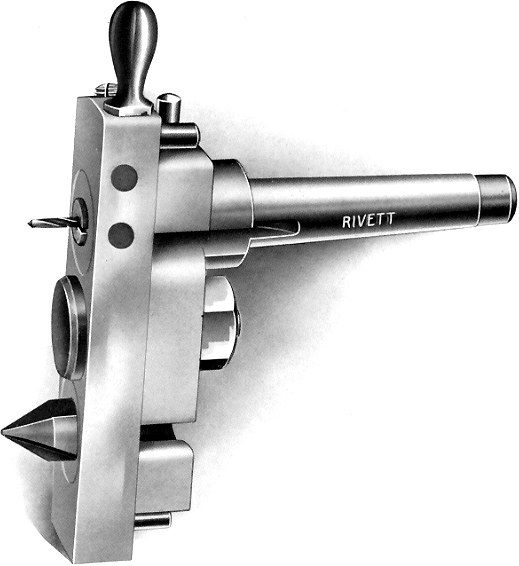
Off-set centre and drill unit
|
|
|
|
|
|
|
|
|
|
 |
|
|
 |
|
|
|
|
|
|
|
|
|
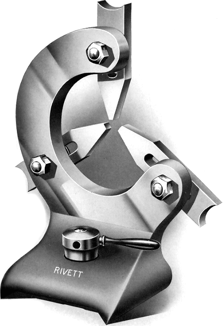
A certain elegant beauty of form: Rivett 8-inch Precision travelling and fixed steadied
|
|
|
|
|
|
|
|
|
|
|
|
|
|
|