|
Home Machine Tool Archive Machine-tools Sale & Wanted Toolroom Lathes Porter-Cable Home Page Porter-Cable Milling Attachment |
|
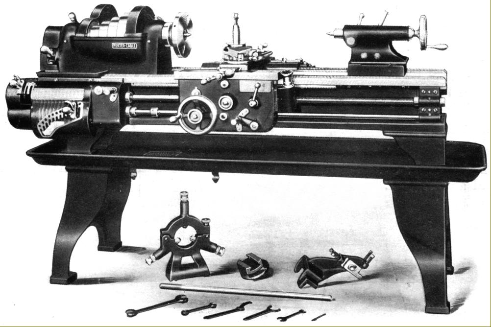
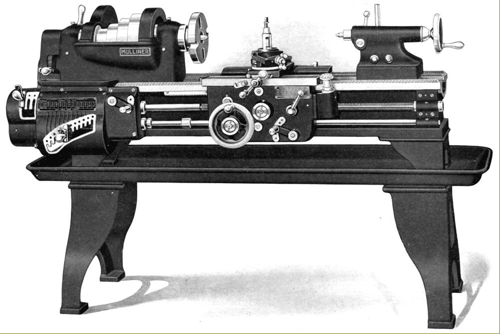
In reality a Mulliner-Enlund lathe (and looking very Hendey-like in its general appearance), the Porter-Cable "Toolroom" lathe was built in 12-inch and 14-inch swings. A machine dating from post 1910, for its era the lathe was entirely conventional and resembled, in all its parts, an ordinary American "engine" lathe - a type known in the UK as a BGSC (backgeared and screwcutting) centre lathe. Having bought out Mulliner-Enlund, Porter-Cable continued to use the original advertising literature and artwork; on some examples the Mulliner-Elund name was retained but the address changed to Syracuse, N.Y., while others were marked with three names as: Mulliner-Edlund Tool Compnay, Inc., Syracuse, N.Y. ; The Porter-Cable Machine Company, Successors and The Portland Machinery Co. Portland, Oregon. The lathe was listed as both a "Toolrooom" model (which might have been an advertising ploy, or may have reflected a genuine attempt to produce a lathe with better-than-average accuracy) and as the 12" and 14" Mulliner Quick Change Lathes. If there were any differences, at this distance in time, it's impossible to say. |
|
|
|
|
|
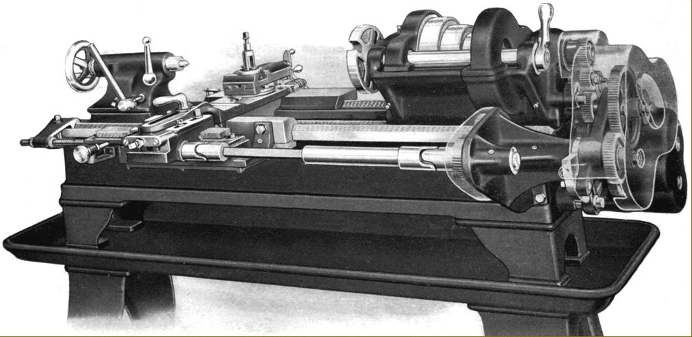
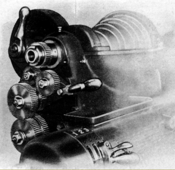
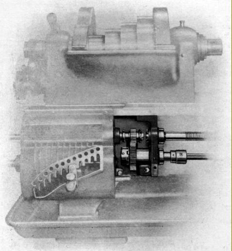
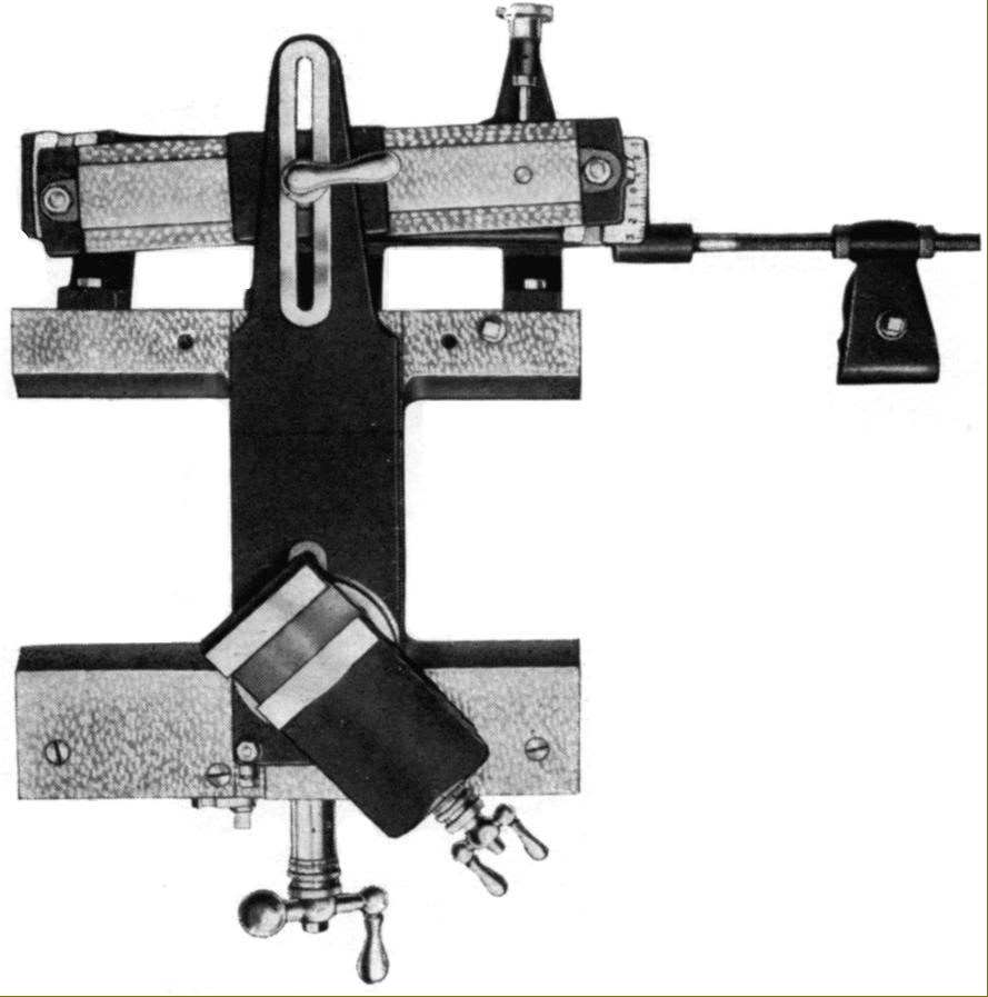
Porter-Cable and Mulliner-Enlund lathe with Relieving Attachment. A popular option on lathe spanning the late 19th and early 20th centuries, it was designed to do under power what had previously often been done by hand - to accurately relieve (or back off) the teeth of taps, cutters, hobs and milling cutters - items that were often made in the factory in which they were to be used. |
|
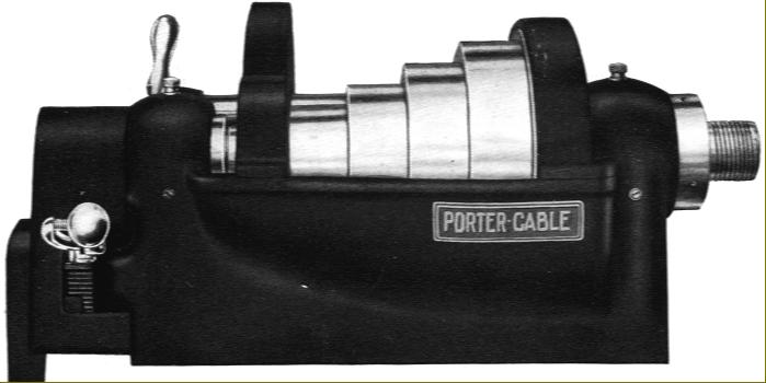
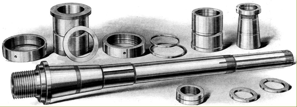
With the casting running up to the centre-line of the bearings, the headstock incorporated one of the more important improvements incorporated in lathe design during the early years of the 20th century |
|
Fitted with a 0.50 ground-finish carbon-steel spindle tapered at the front and parallel at the rear, the headstock held special analysis bronze bearings that could be pulled into their tapered seats by ring nuts to set the running clearance. Thrust was taken by hardened washers with lubrication provided by ring oilers that dipped into wells of lubricant below each bearing. |
|
|
|
|
|
|
|
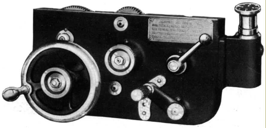
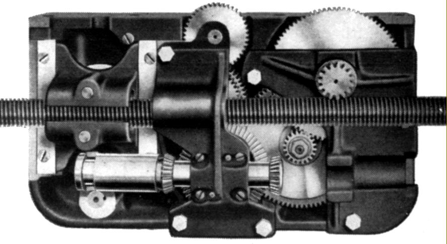
Fitted with a keyway, the power shaft passed through the single-sided, open apron where it passed though and drove, via a key, a sleeve that was equipped, at each end, with a bevel gear. The sleeve was arranged to move sideways, under the control of a 3-position quadrant lever mounted on the apron's front face that, in its middle position centralised the sleeve and, when lifted or lowered into its other positions, caused one or other of the sleeve bevel gears to mesh with the left or right-hand side of a large bevel gear carried centrally on the inside face of the apron. The large bevel gear was connect to a train of gears that directed the drive to produce either a sliding or surfacing feed - the movement of the lever having the secondary function of engaging the appropriate gear train. Once selected, the feeds were engaged by a knurled-edge handwheel that, when turned, drew in a clutch to transmit the drive. |
|
The gearbox output shaft was divorced from both power-shaft and leadscrew and connected to each by a sliding gear and multi-tooth dog clutch that allowed only one to be engaged at a time. |
|
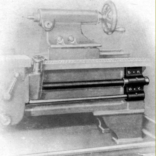
At the tailstock end of the bed the leadscrew hanger bearing was dowelled and bolted to the bed and the screw end fitted with adjustable thrust collars, the headstock end being free to float and so absorb small changes in length due to expansion during the working day. |
|
|
|
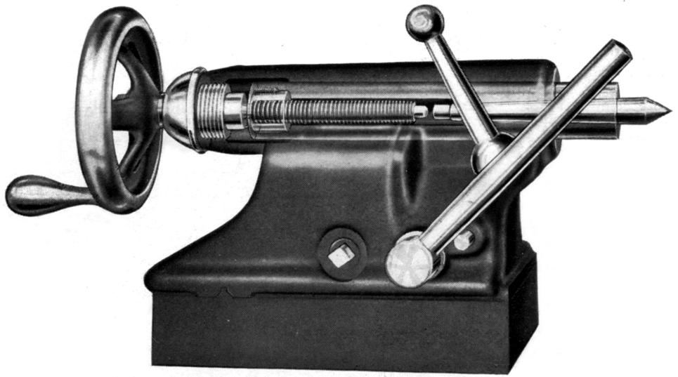
4 inches per foot. The set-over was adjusted by a screw, a useful facility often omitted by other makers |
|
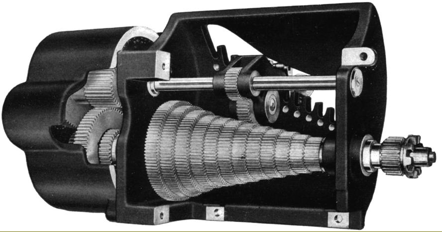
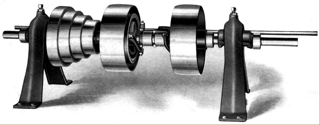
Well-made countershaft with integral, toggle-operated clutch. The central wheels were 12 inches in diameter and 4.5 inches wide. On the 12-inch lathe the countershaft was intended to run at between 106 to 135 r.p.m. and on the 14-inch (with a set of smaller-diameter cone pulleys) at 160 to 210 r.p.m. |
|
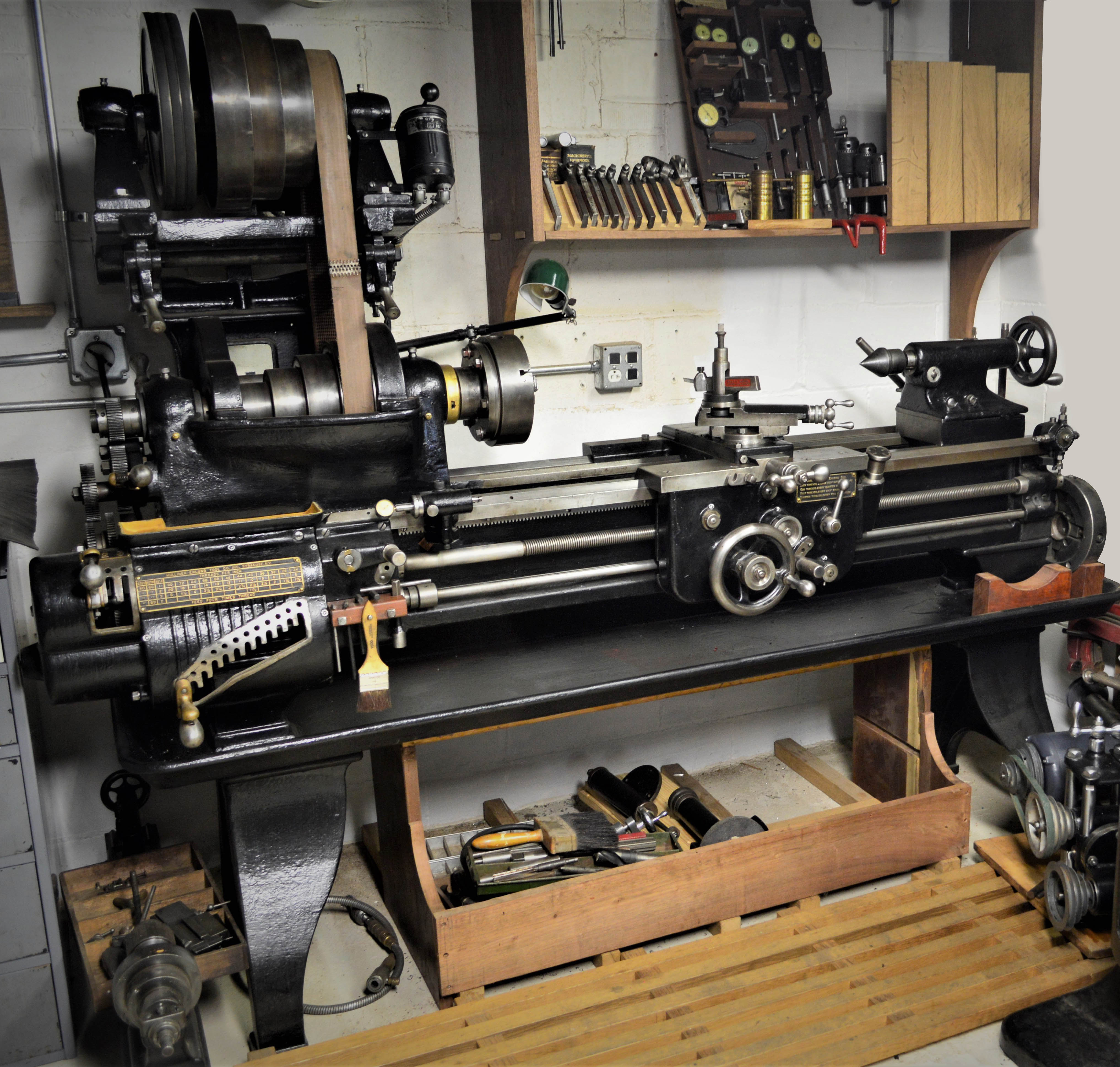
A superbly maintained, 6-foot long bed, Mulliner Enlund 14-inch engine lathe. The cleverly retrofitted overhead drive came from a 1930s South Bend 15" lathe - with its mounting probably necessitating the removal of the lathe's relieving attachment |
|
Toolroom Lathes Home Machine Tool Archive Machine-tools Sale & Wanted |
||