email: tony@lathes.co.uk
Home   Machine Tool Archive   Machine-tools Sale & Wanted
Manuals   Catalogues   Belts   Books  Accessories

Mikron Miniature Precision
Milling Machines Type F75

Mikron Lathes Home Page Larger Mikron Millers  Mikron Milling Accessories   

Mikron Milling Applications   Mikron Miller Photographs  Horizontal & Vertical Mikron

Mikron Catalogues and Manuals are available - Click for details

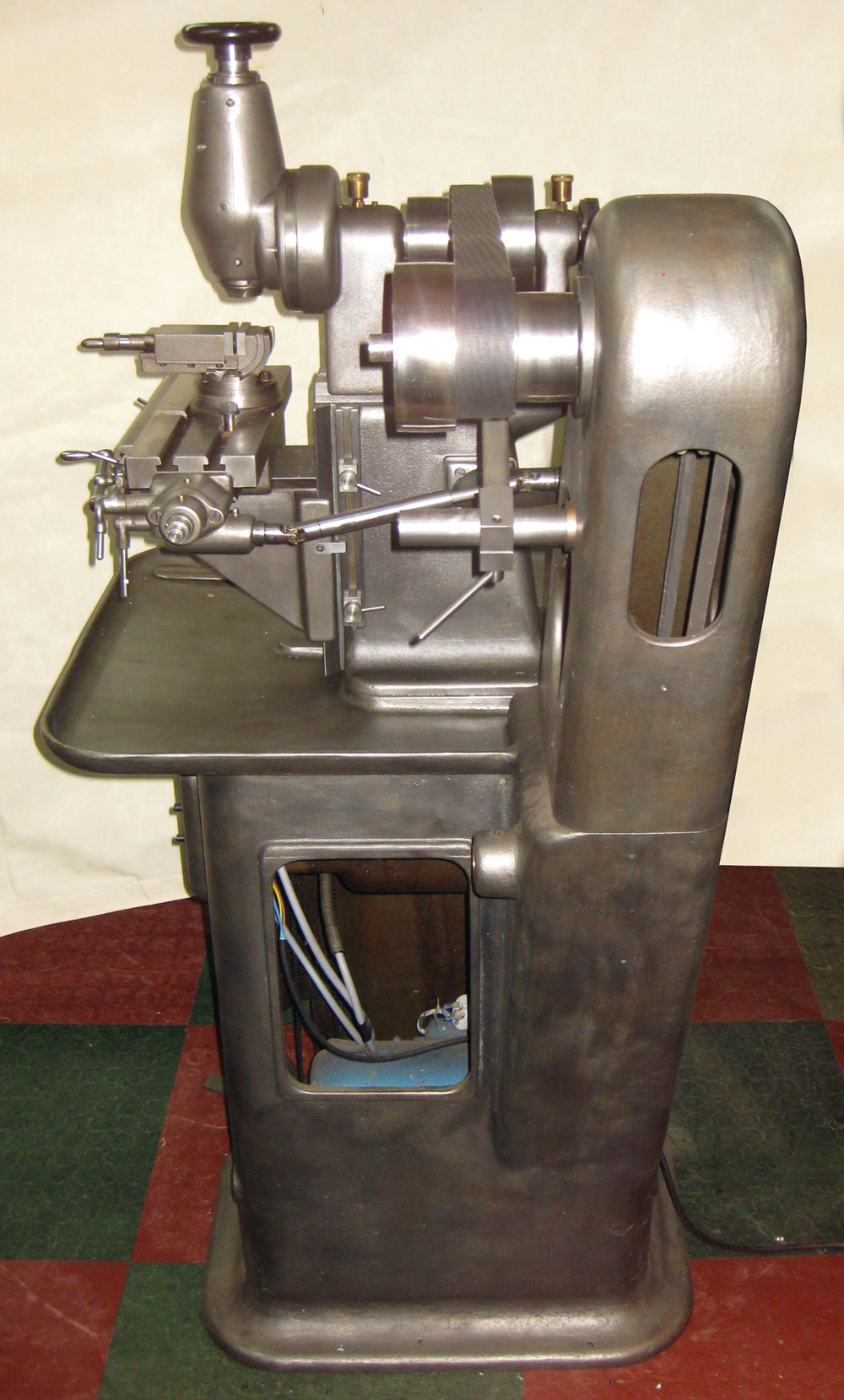
Although the Mikron Company was to eventually build a number of larger precision toolroom-class milling machines of the Deckel FP type (listed as the WF23S, WF3S, WF3-DCM and WF2/3-DCM), for many years they were better known for a range of beautifully finished and very accurate small bench horizontal and vertical models, the Type F75. Like similar models from Stark, The American Watch Tool Company, B.C. Ames, Wade, Pratt & Whitney and others in the U.S.A., Mikron millers all used modified lathe headstocks mounted on a substantial main column with a conventional knee and table assembly. The top of the column was formed with the same section as found on the bed of a Mikron precision bench lathe - a fitting that allowed an instant change from horizontal to vertical modes, as well as permitting the use of a customer's existing lathe headstocks and other accessories. All versions had the same size of table, 360 mm x 115 mm, able to be controlled by either screw or lever feeds. When fitted with screw feeds (Base No. 93) the table travel was 180 mm longitudinally, 70 mm across and 135 mm vertically while lever control (Base No. 94) gave, respectively, 250 mm, 70 mm and 120 mm. The feed screw for the knee was unusual, a "half-nut" in bronze being let into the back of the casting for its full height with the short, large-diameter screw "resting" against it (pictures of this assembly are on this page). Each table axis was fitted with an adjustable length stop with lever locks - those these appear to have been missing on early machines.
Although based on the design of the ordinary lathe headstocks, the ones for the milling machine were, however, specially adapted to their task. The basic unit was the No. 95, with no arbor support and intended only for simple stub milling. Instead of the 4-step cone pulley of the lathe headstock this used a wider 3-step type (diameters 85, 107 and 125 mm to take a 40 mm wide belt) with the hardened, ground and lapped spindle running in parallel bronze bearings tapered on their outside for adjustment and with a ball-race thrust bearing. Collets supplied by the makers were of their own version of the common Schaublin W20 type - though ordinary Schaublin ones can be used with the right drawbar. When run from a 2-speed Brown-Boveri 1400/1700 r.p.m. motor with a double-step pulley, the drive had 12 speeds from 120 to 1350 r.p.m. However, if fitted with a 3 : 1 epicyclic reduction gearbox within the pulley (as Headstock No. 95a), this number rose to 24, spanning a very useful 30 to 1350 r.p.m. However, some charts give the standard headstock speed range - with a two-speed motor - as 95 to 1100 r.p.m. and with the epicyclic gearing from 65 to 1100 r.p.m. The built-in gearing was of beautiful construction and activated by a clamp screw positioned at a tangent to the pulley and then locking the centre part of the mechanism by the use of a pin - though this pin was not just pushed in, to satisfy Mikron's high standards it was moved by rack-and-pinion activated by a knurled-edged dial protruding from the front face of the headstock in line with the rearmost pulley. When the pin was engaged it held the inner drum from rotating, so causing the sun and planet pinions inside to turn the right-hand drum - and so the spindle to which it is attached - to turn at a reduced speed. A close-up of this type and its control elements can be seen on this page and details of how these epicyclic gear systems work here.
If the requirement was for conventional horizontal milling with a supported arbor, headstock No. 99 could be ordered. Again, this used the main components from the No. 95, but with the addition of a built-in, round overarm. For vertical milling headstock No. 97 was provided with this, again, based on the No. 95 and using the same spindle, bearing and pulley assembly. The drive from the horizontal spindle to the vertical was by bevel gears and the unit could be swivelled through 90° in either direction and so, in combination with other fittings, allowing a wide variety of work to be tackled.
Unusually for a small milling machine, a table power-feed unit was available (No. 98) and, driven from a small 3-step pulley on the headstock via a carden shaft to a housing on the right-hand end of the table that held worm-and-wheel gearing and a dog clutch. Three feed rates were provided of 0.05, 0.10 and 0.20 mm per revolution of the spindle. Several useful, well-made accessories were also listed by the manufacturer, these covering all the uses to which the miller might be put. Items included a basic, non-motorised stand, plain and swivelling head index heads, an indexing head that could be attached to the milling machine (and lathes) headstock spindles, an indexing head for spiral milling (only for use on machines with power feed to the table), swivel-base and swivelling and tilting machine vices, dividing heads with tailstocks and 3-jaw chucks, high-speed milling quill, rotary tables, coolant pump and tank and a sub-stable (No. 113) that fitted on top of the ordinary table and could be swung 5° in either direction for taper milling. A collection of interesting photographs of Mikron milling machines can be found here and here..

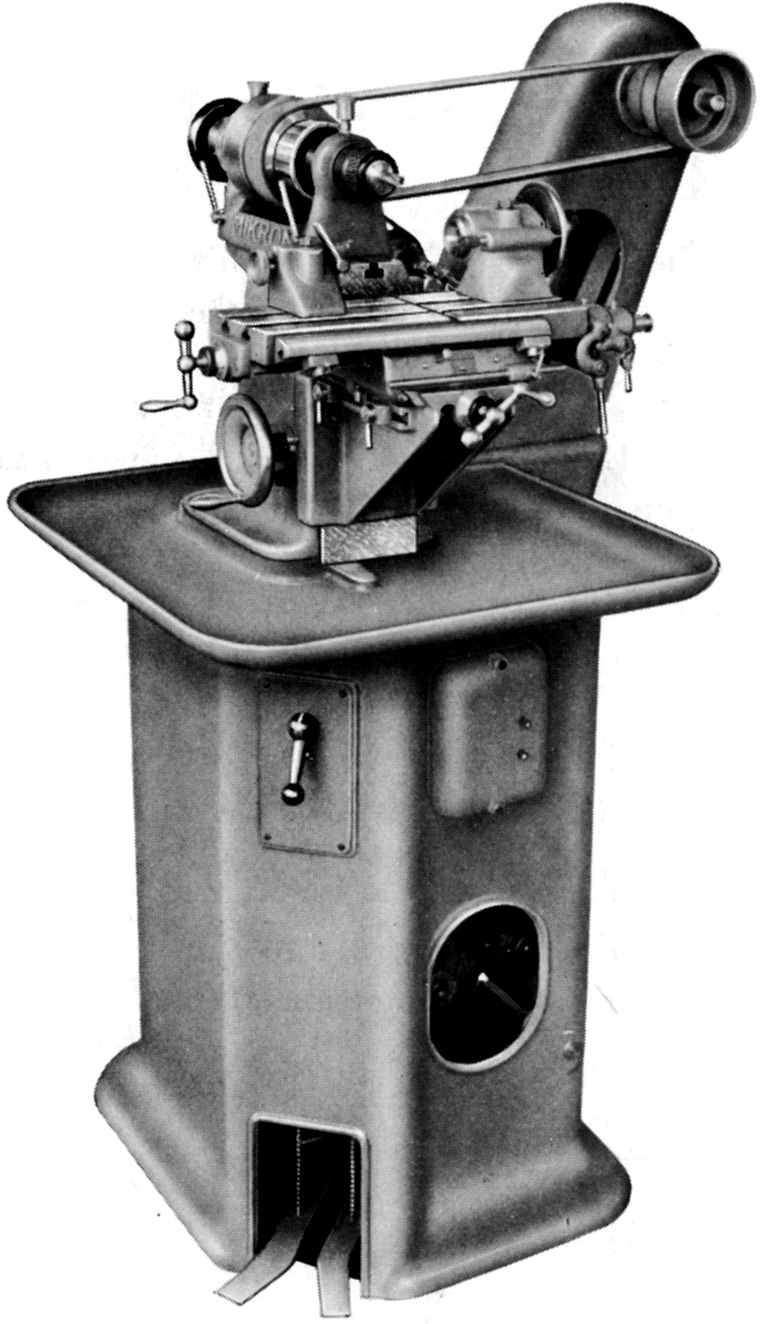
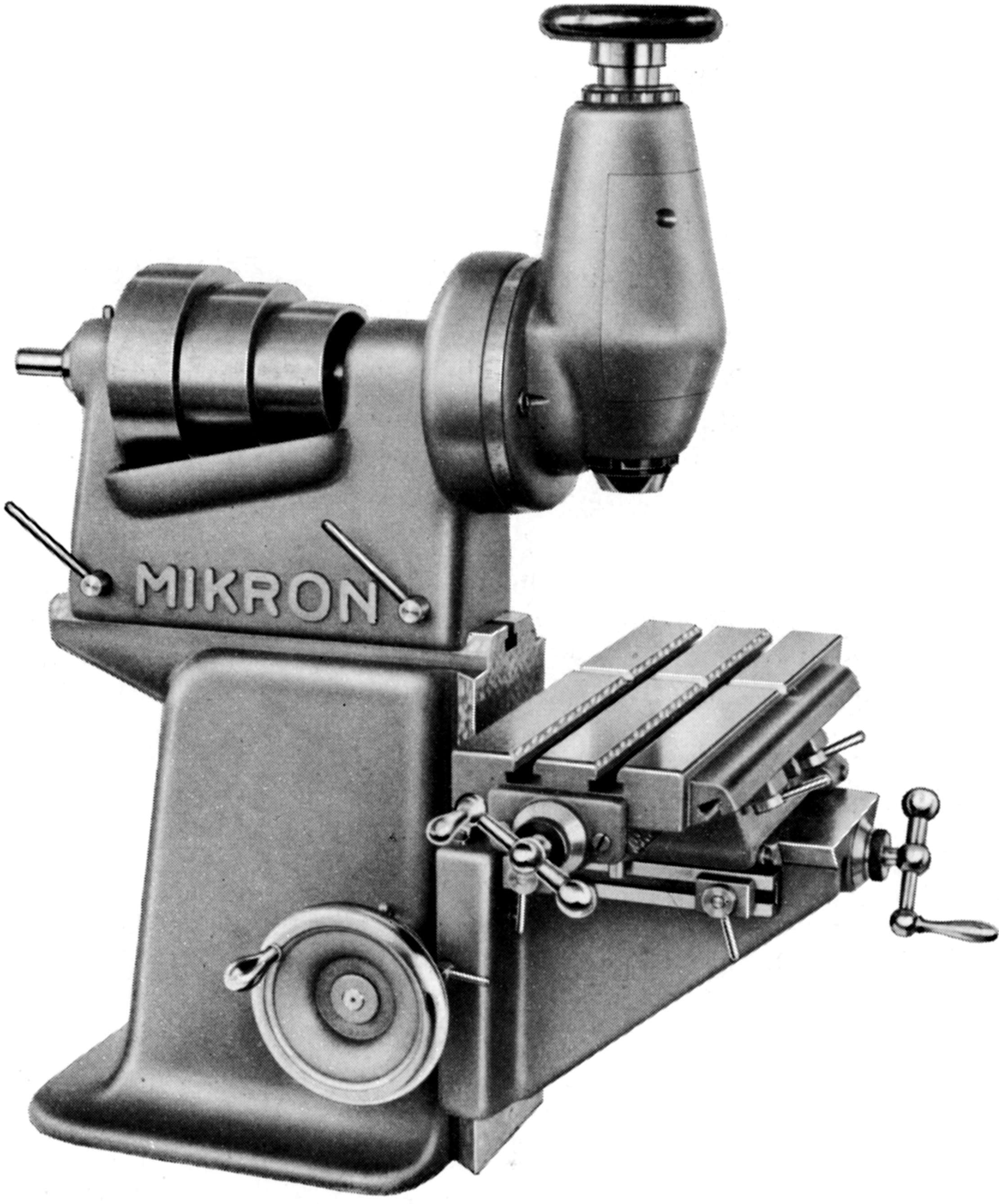
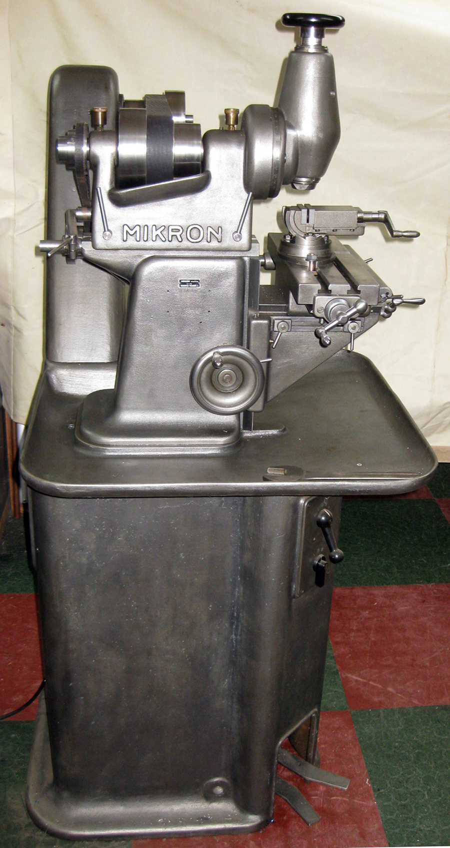
Mikron miller mounted on the maker's No. 93 base. Other elements include: Headstock No. 95; automatic table feed No. 98; plain indexing head No. 99; tailstock No. 11 and milling arbor No. 111. This configuration was intended to be driven by a 2-speed 700/1400 r.p.m. motor to give 12 speeds from 120 to 1350 r.p.m. on the No. 95 or 24 speeds from 40 to 1350 r.p.m on the epicyclic-reduction geared headstock No. 95a. Note the considerable distance from countershaft to spindle head - a useful precaution with flat-belt drive that works more effectively the further apart (within reason) the pulleys are positioned

Stand No. 124 with countershaft and electrical equipment.

Horizontal milling machine with the No. 93 all-screw-feed table assembly and the No. 95 headstock

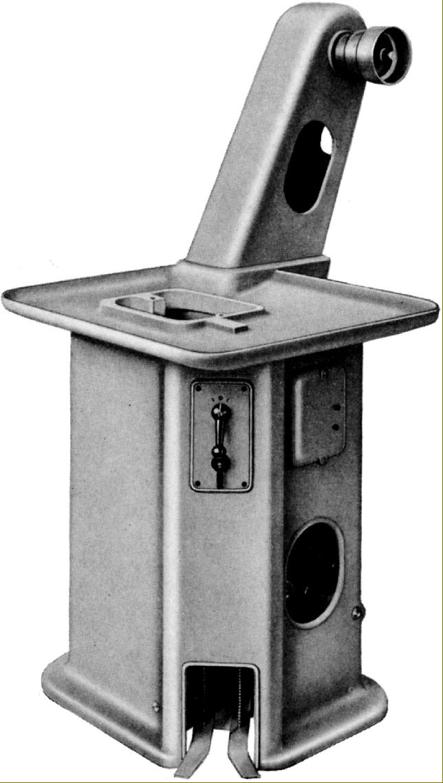
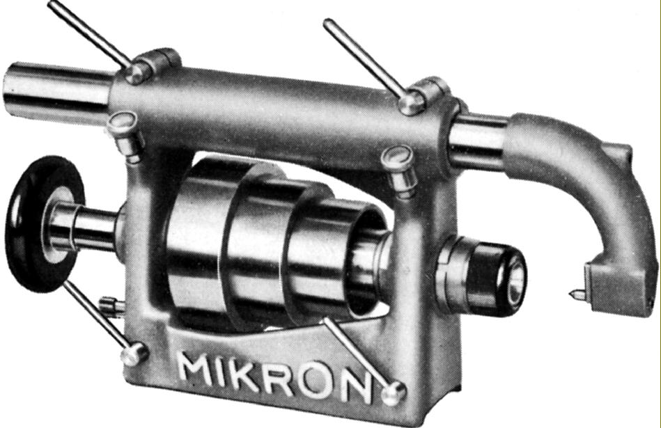
Vertical milling machine with screw-feed table assembly No. 93 and vertical head No. 97. The head, a particularly rigid structure, was able to run up to 2000 r.p.m.

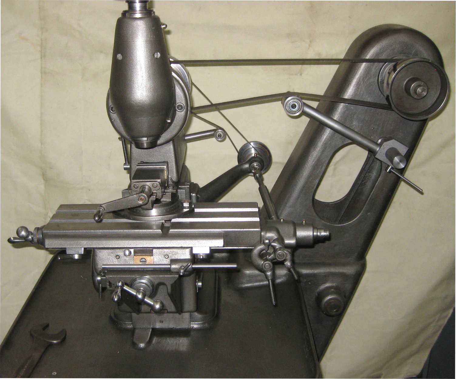
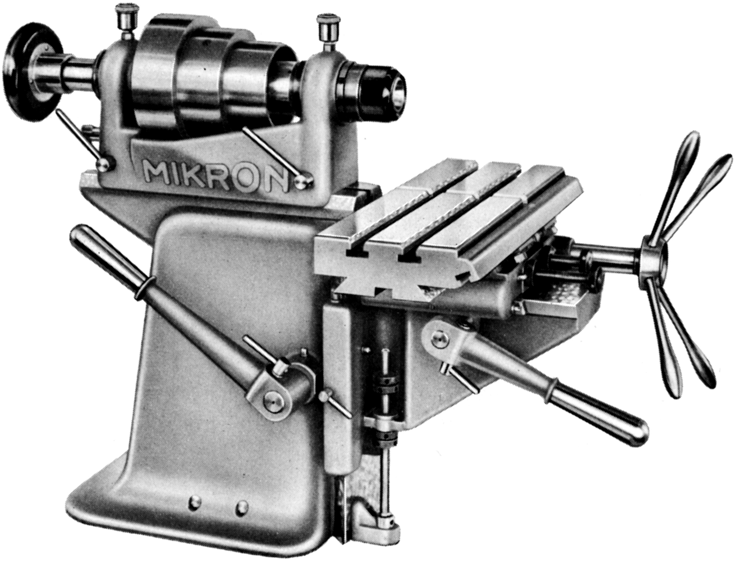
Horizontal milling machine designed for the mass production of small parts needing high speeds. The standard headstock supplied was the No. 95 but this could be replaced, if even higher speeds were required, by the 6,000 r.p.m. roller bearing lathe headstock No. 15a.  With all-lever control of the table movements the weight of the table and knee was counterbalanced by a strong spring contained within the column. Apart from the  automatic table-feed unit No. 98 and the spiral dividing head No. 103 all other standard milling accessories could be fitted.

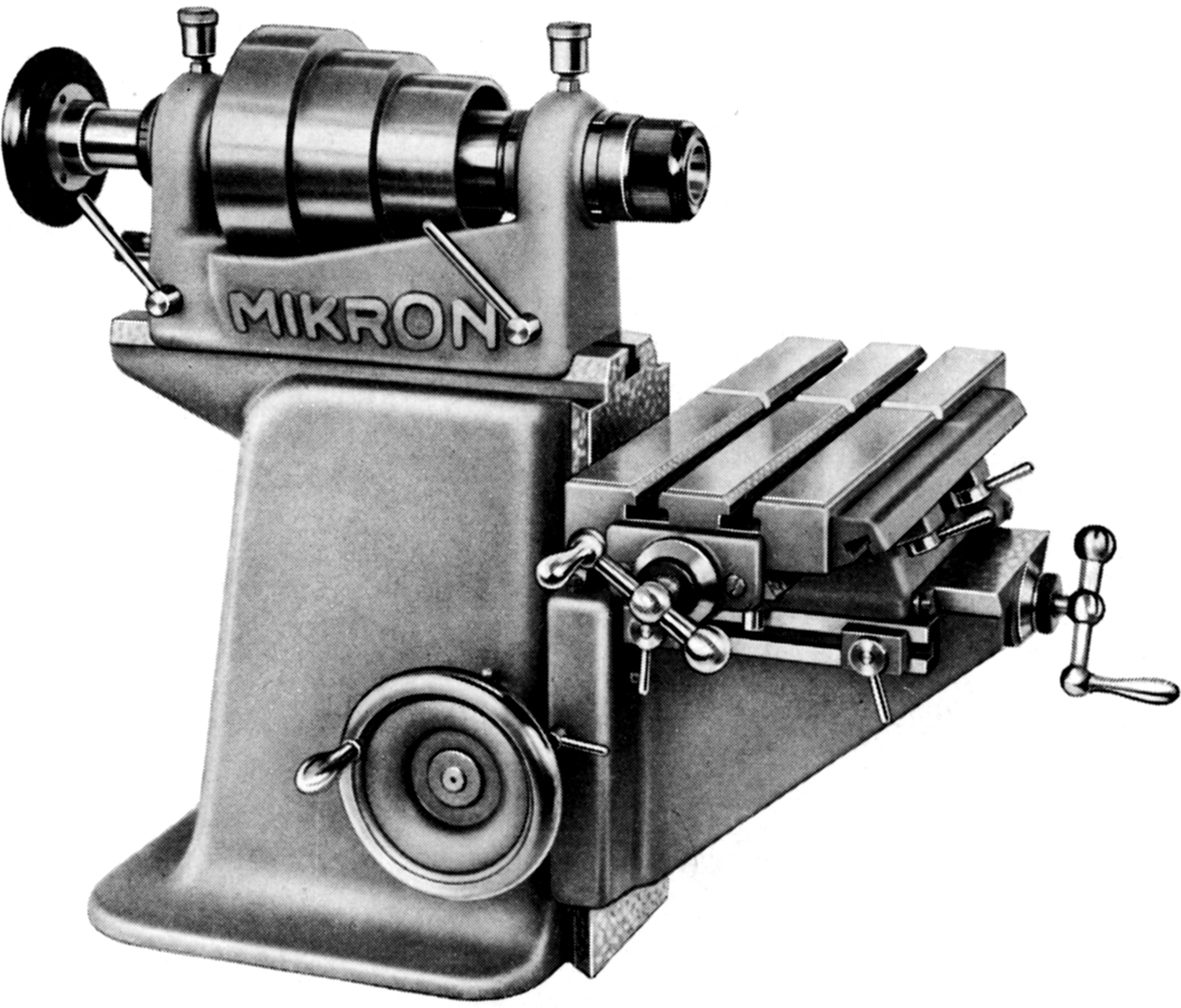
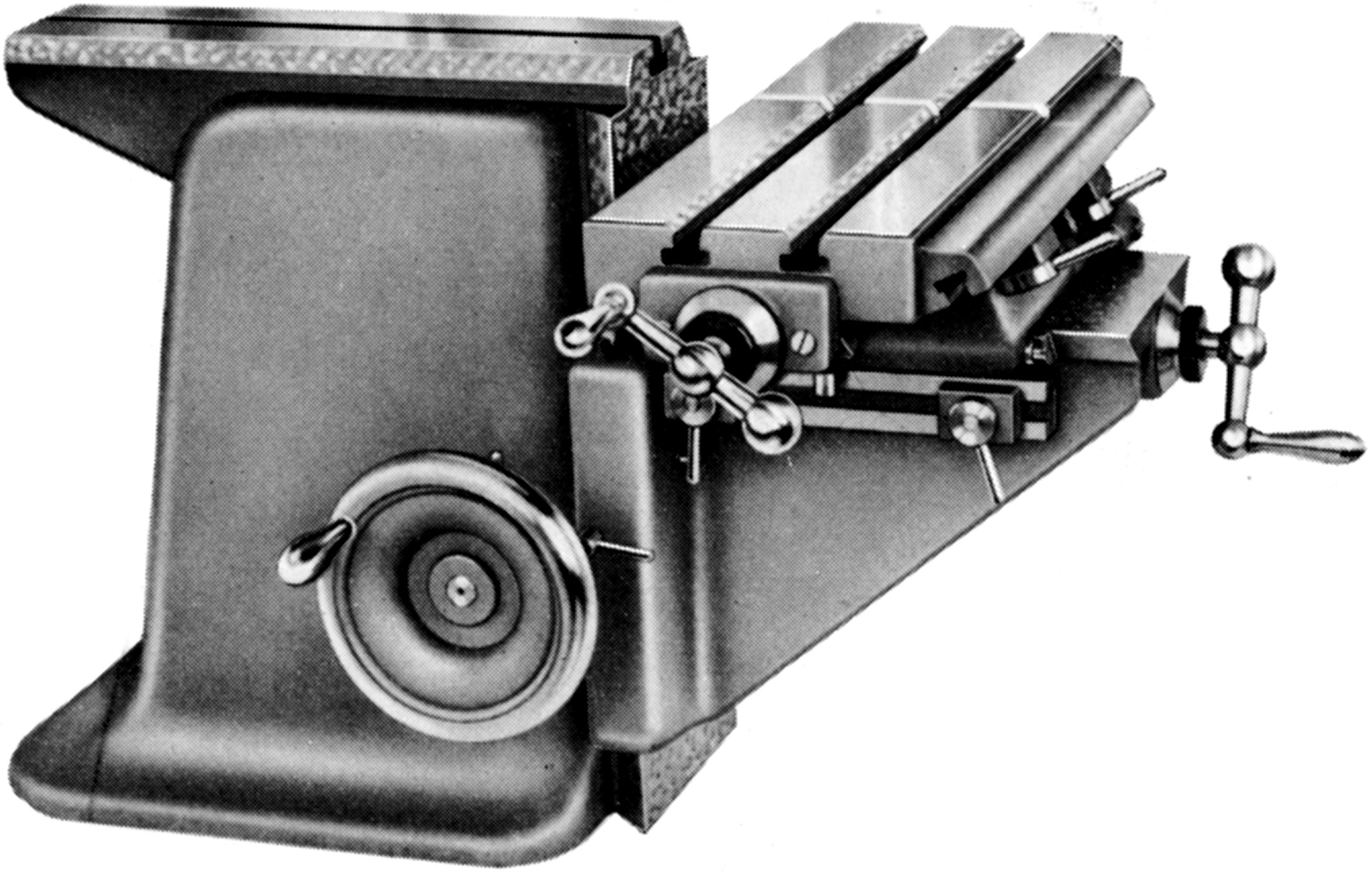
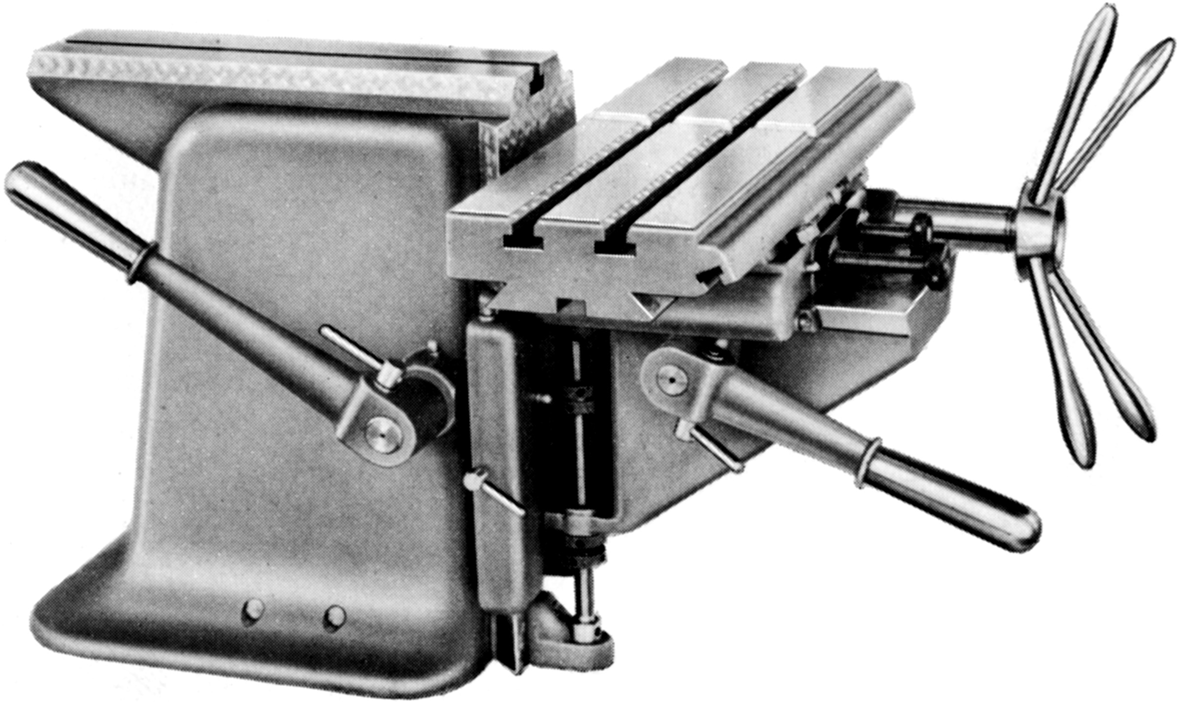
Milling machine base and screw-feed table assembly No. 93. This unit could accept all the milling headstocks (95, 95a, 96, 96a and 97 as well as the conventional headstocks from the lathe range. It was therefore possible, if a part had been turned on a lathe to keep the part in situ, transfer the headstock to the miller and mount the indexing head No. 101 and the quill No. 112 to complete the job.

Milling machine base and all-lever-feed table assembly No. 94

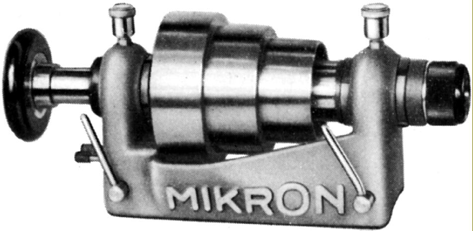
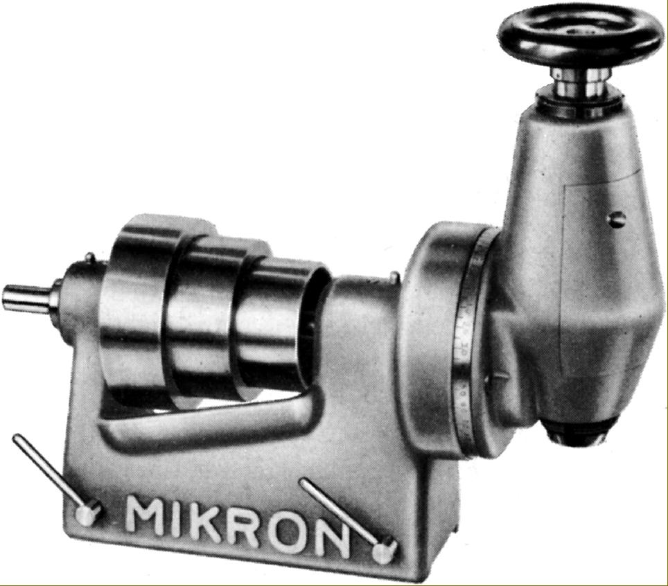
Milling Machine Headstock No. 95. 3-step cone pulley (diameters 85, 107 and 125 mm) for 40 mm wide belt. The hardened ground and lapped spindle ran in parallel bronze bearings tapered on their outside for adjustment.

Headstock 95a. As headstock 95 but with the addition of a 3 : 1  epicyclic reduction gear within the pulley. 

Headstock 96 with built-in overarm. The spindle, bearings and pulley were the same as those used in the No. 95

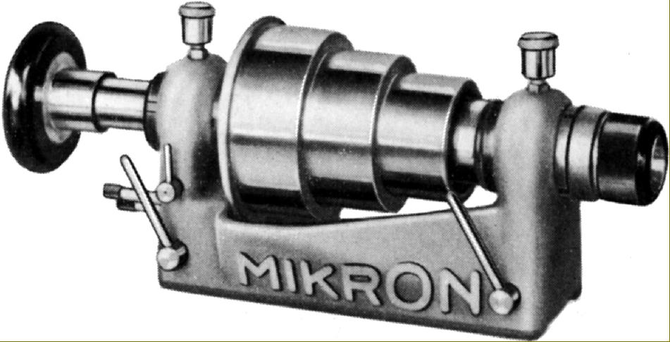
Headstock No. 97 Based on the No. 95 with the same spindle, bearing and pulley assembly. The drive from the horizontal spindle to the vertical was by bevel gears and the unit could be swivelled through 90° in either direction

Mikron Lathes Home Page Larger Mikron Millers  Mikron Milling Accessories   

Mikron Milling Applications   Mikron Miller Photographs  Horizontal & Vertical Mikron

Mikron Catalogues and Manuals are available - Click for details

MIKRON Miniature Precision
Milling Machines

email: tony@lathes.co.uk
Home   Machine Tool Archive   Machine-tools Sale & Wanted
Manuals   Catalogues   Belts   Books  Accessories