 |
|
|
|
|
|
|
|
|
|
|
|
|
|
|
|
|
|
|
|
|
|
|
|
|
|
|
|
|
|
|
|
|
|
|
|
|
|
|
|
|
|
|
|
|
|
|
|
|
|
|
|
|
|
|
|
|
|
|
|
|
|
|
|
|
|
|
|
|
|
|
|
|
|
|
|
|
|
|
|
|
|
|
|
|
|
|
|
|
|
|
|
|
|
|
|
|
|
|
|
|
|
|
|
|
|
|
|
|
|
|
|
|
|
|
|
|
|
|
|
|
|
|
|
|
|
|
|
|
|
|
|
|
|
|
|
|
|
|
|
|
|
|
|
|
|
|
|
|
|
|
|
|
|
|
|
|
|
|
|
|
|
|
|
|
|
|
|
|
|
|
|
|
|
|
|
|
|
|
|
|
|
|
|
|
|
|
|
|
|
|
|
|
|
|
|
|
|
|
|
|
|
|
|
|
|
|
|
|
|
|
|
|
|
|
|
|
|
|
|
|
|
|
|
|
Available in an almost bewildering variety of special forms, the Leinen precision plain-turning lathes could be ordered for both toolroom and production work.
Established since the late 1800s as a maker of very high-quality machine tools, from the 1920s to the 1960s Leinen offered a range of precision lathes designed to meet the needs of both toolmakers and production engineers. Like the very similar lathes from the competing German firm of G.Boley, although they differed in size and detailed design they all shared top quality materials that had been machined with care and assembled by skilled craftsmen to meet exacting standards of performance. In addition to the machines illustrated in the ordinary catalogue, many special-purpose units were also constructed either as one-offs, or in small batches to special order. A huge number of accessories were also listed for these lathes some of which, together with those for the precision plain-turning models, are here.
Models were divided into Types and sizes - the former being the A, B, C, etc and the latter 1, 2, 3, 4, and 5 etc. Specifications (and retro-fit accessories) were as follows:
R = lathes with backgear
P = lathes with a simple thread-chasing attachment
PW = lathes with a chasing attachment using changewheels
G = lathes with a screwcutting attachment using changewheels and a universally-jointed and sliding splined shaft drive to the top slide
L = lathes with a leadscrew and changewheels for screwcutting
LZ = lathes with a leadscrew and a powershaft, the latter providing a separate feed for the carriage sliding feed
S = lever-operated collet closer on the headstock that worked with the spindle running
H = hand-lever operated slides (usually together with a lever-operated collet closer)
F = mounted on cast-iron legs with a hardwood top and locking storage drawer
Leinen were always willing to build any number of combinations of features into a lathe and examples have been found where the precise catalogue specification was not illustrated, or listed, but easily deducted from the above list.
Formed with integral feet, beds were cast from a grade of especially hard iron and heavily ribbed on the inside faces. They were formed with one V and one flat way (hand scraped against master gauges) with a central T-slot that allowed the headstock and tailstock to be firmly held in any suitable position by the usual type of simple eccentric lock.
Hardened and ground and bored to take draw-in collets, the headstock spindles ran in hardened and ground double conical steel bearings with end thrust taken by a ball race. Noses were threaded to allow the easy mounting of chucks and faceplates (some makers of this class of lathe insisted on such items being carried on collets) with a protective nosepiece provided for use when collets were employed. After assembly headstocks were test run for several hours at 3000 r.p.m. before being fitted to a lathe bed. Although the smallest machine, the A-1-L, had an ordinary full-width backgear, the others all used a type where the gears were clustered just inboard of the spindle-nose bearing, this compact arrangement (as also used by many other makers including Myford) also allowing easy lubrication of the gears and bearings.
Compound slide rests were typical of the type with a very long travel top slide (this being the only means of taking a long cut on the plain models) and the usual too-small though beautifully engraved, tapered surface zeroing micrometer dials - though by the early 1930s similar models from Schaublin and Mikron in Switzerland (and Hardinge in America) had all improved this aspect of their similar lathes. To improve rigidity he slide end plates, supporting the outer end of the feed screws, were secured by four instead of the usual two bolts.
Smallest of the Leinen lathes listed during the 1920s and 1930s were the plain-turning A-1 and the similar but backgeared and screwcutting A-1-L (the latter one of the smallest lathes intended for professional use to be so specified). Both had a centre height of 60 mm and a bed 500 mm long - with the former was able to admit 270 mm between centres and the latter 250 mm. Although the main components were similar - and the tailstock, compound slide rest and spindle bearings assembly identical - the two lathes were, naturally, very different in detail. The A-1, which weight 30 lbs, was an entirely plain lathe with the compound slide held to the V- and flat-way bed by a threaded rod that ended in a turnbuckle, the headstock secured by two eccentric bolts running in a T-slot and the tailstock by an eccentric cross shaft turned by a lever. The more sophisticated (and rare) A-1-L weighed 90 lbs and was both backgeared and screwcutting - changewheels (a set of twenty was provided) being carried on a bracket pivoting from the leadscrew's headstock-end bearing bracket. As the carriage was fitted with a full nut on the leadscrew, instead of clasp nuts, the bracket also incorporated an enclosed, quadrant-arm operated dog clutch that allowed the drive to be engaged and disengaged at will (an identical arrangement being fitted on the well-known Drummond 3.5-inch flat bed from 1912 onwards).
Drive to the 8 mm bore headstock spindle was by round belt passing over a 4-step pulley on the A-1 and a 3-step on the A-1-L - with the maker offering a number of remote countershafts for wall, ceiling or bench mounting. Collets were of the draw-in kind with a single collet and drawbar supplied as part of the standard equipment. Also included with each new lathe were a hand T-rest, male and female centres, a nut to protect the spindle thread and a driving plate with an adjustable striker pin. In addition the A-1-L had a travelling steady, the necessary changewheels and a screwcutting chart.
Next in size was a series of plain-turning models designated A2 to D3, all of virtually identical appearance but different dimensions, specifications and with a range of optional fittings including backgear, screwcutting by thread chasing or changewheels and with the slides, collet closers and tailstock operated by screw or lever feed. The range was also available with backgear, and important fitting designated by the suffix R. Although all were intended for drive by flat belt from the robust V6 ring-oiled countershaft, models based on the A2, B2, A3, B3, C3, and D3 sizes could be supplied for drive by a round rope.
No matter what other changes were made to the specification - longer beds, backgears, screwcutting, etc. - the centre height remained the same for the designating letter e.g. all A-2 Models were 80 mm and all D-3 130 mm..
|
|
|
|
|
|
|
|
|
|
|
|
|
|
|
|
 |
|
|
|
|
|
|
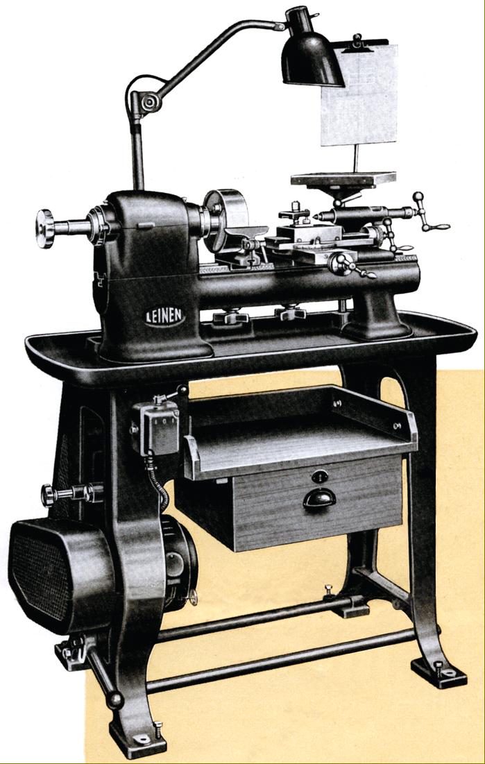
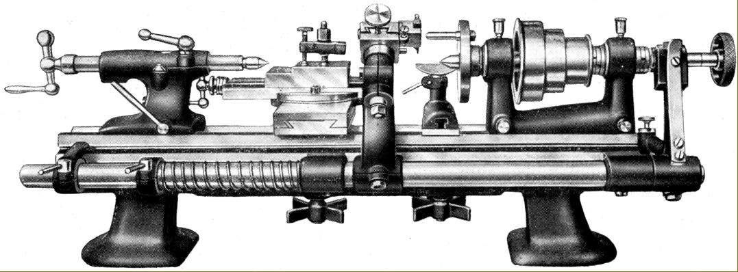
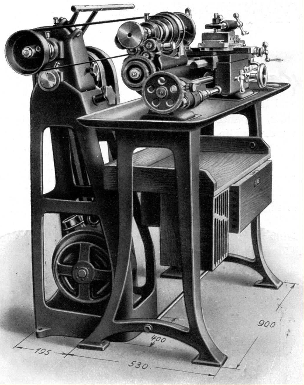
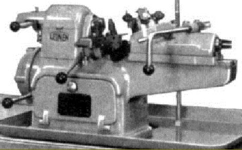
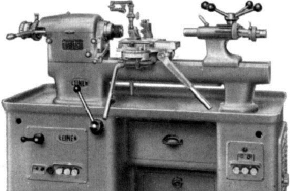
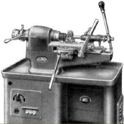
Circa mid 1940s Leinen Type L3n 100 mm x 320 mm plain-tuning precision lathe mounted on the maker's self-contained under-drive stand
|
|
|
|
|
|
|
|
 |
|
|
|
|
|
|
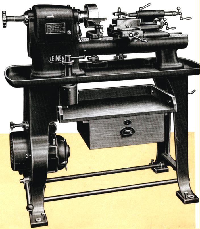
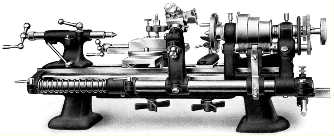
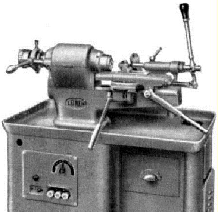
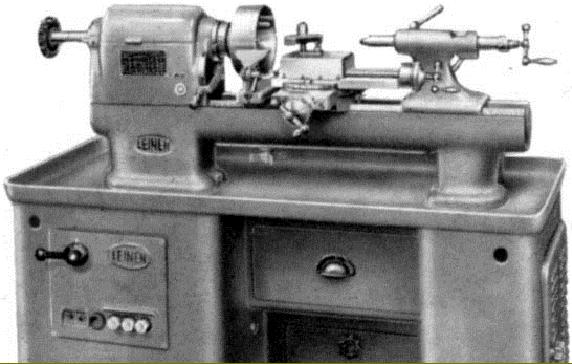
Circa mid 1940s Leinen Type L4R-su 130 mm x 400 mm plain-tuning precision lathe mounted on the maker's self-contained under-drive stand
|
|
|
|
|
|
|
|
 |
|
|
|
|
|
|
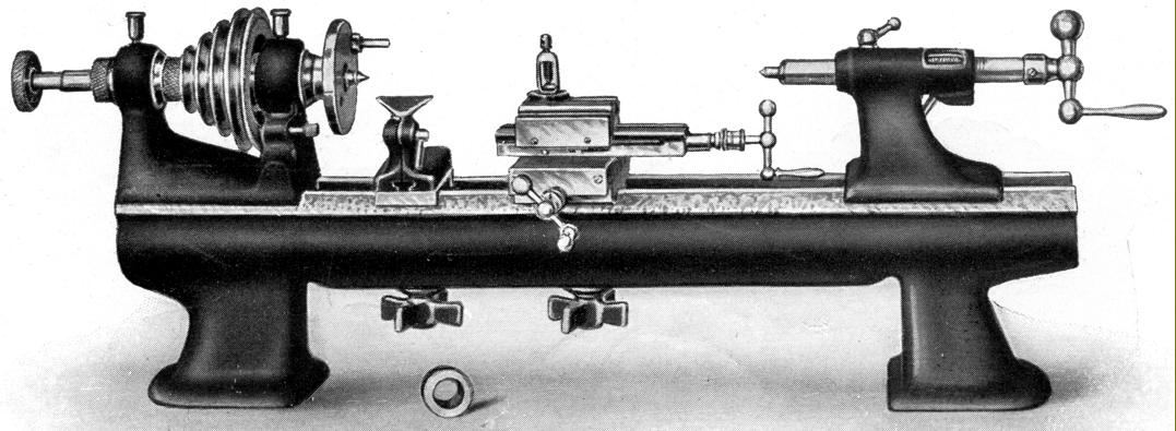
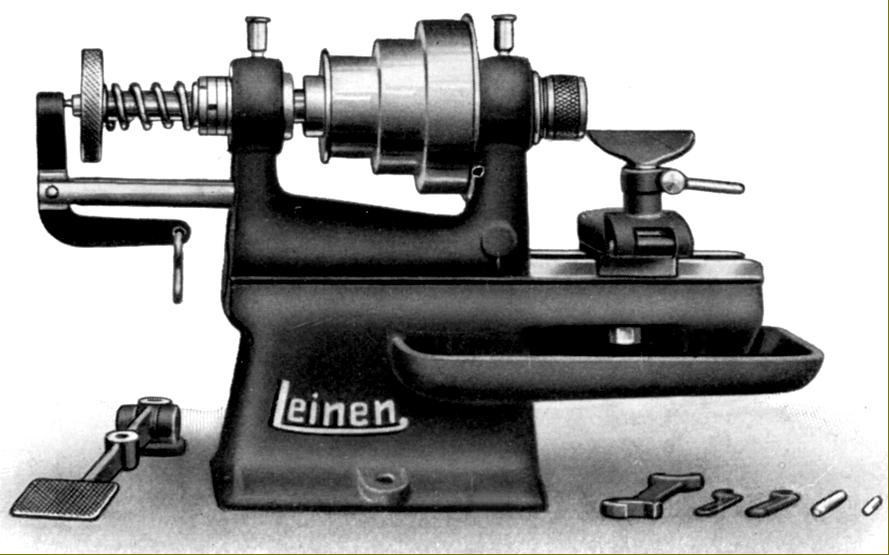
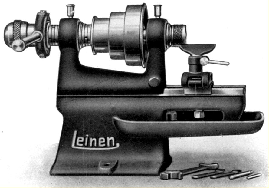
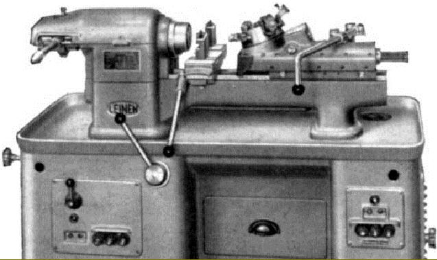
Smallest of the Leinen lathes listed during the 1920s and 1930s this period were the plain-turning A-1 (below) and the similar but backgeared and screwcutting A-1-L (above, one of the smallest lathes intended for professional use to be so specified).
|
|
|
|
|
|
|
|
 |
|
|
|
|
|
|
|
|
|
|
|
 |
|
|
|
|
|
|
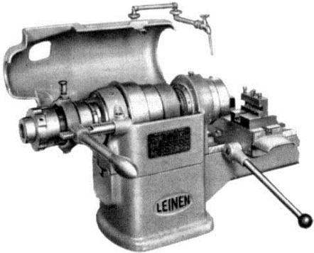
Larger precision lathes Types A2, B2, A3, B3, C3, D3, E3 and A4. All were similar to the above machine but of different capacity.
|
|
|
|
|
|
|
|
 |
|
|
|
|
|
|
Larger precision lathes Types A2S, B2S, A3S
and B3S with lever-operated collet closer
|
|
|
|
|
|
|
|
 |
|
|
|
|
|
|
Larger precision lathes Types A3H and B3H with collet closer, compound slide and tailstock all lever operated
|
|
|
|
|
|
|
|
 |
|
|
|
|
|
|
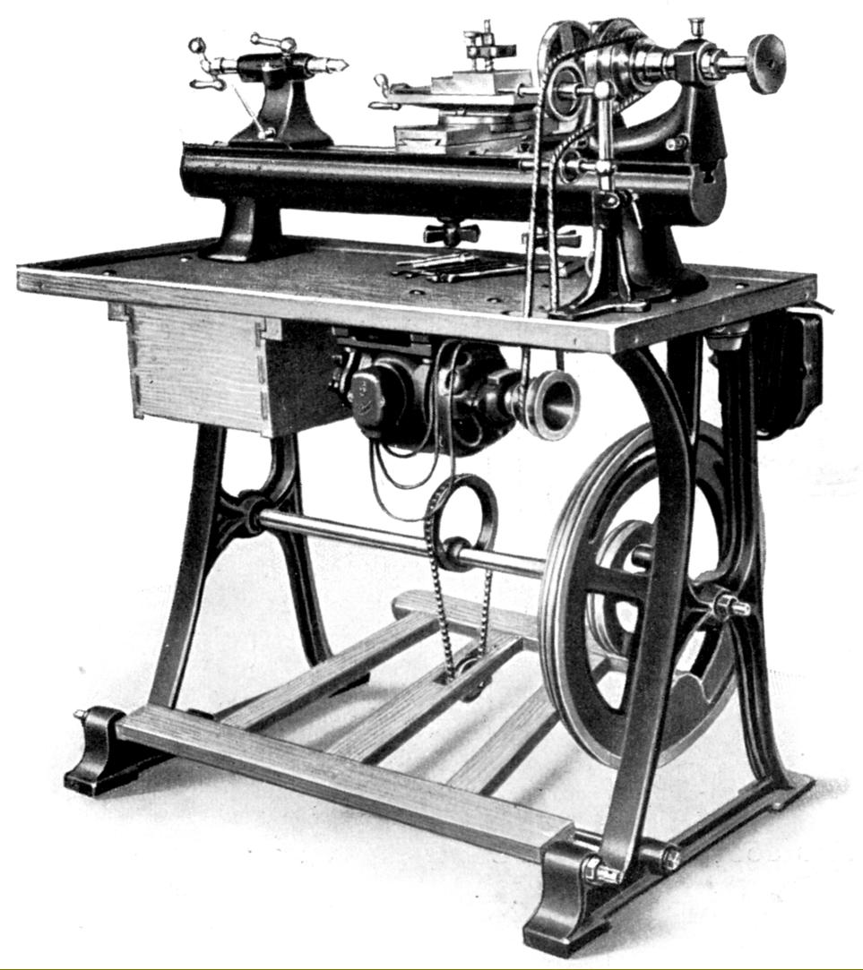
Leinen Type e3 drive for installation beneath the maker's treadle stand to give both foot-treadle and electric drive. The system included a most useful pulley assembly mounted at the back of the bed that both guided the electrically driven belt around the headstock pulley while giving additional wrap-around to produce a more efficient drive
|
|
|
|
|
|
|
|
 |
|
|
|
|
|
|
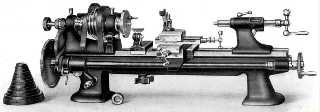
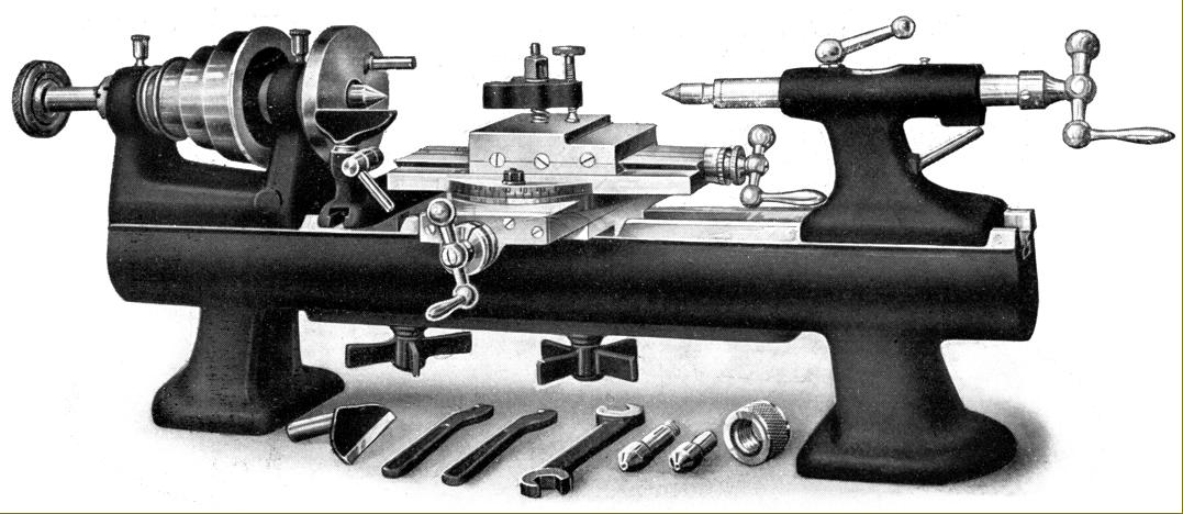
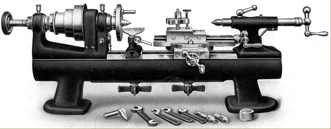
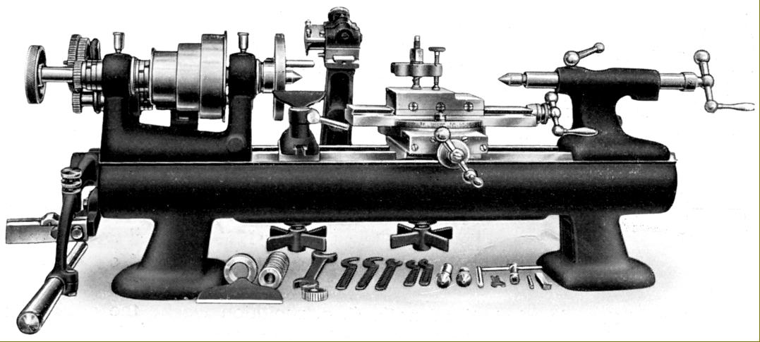
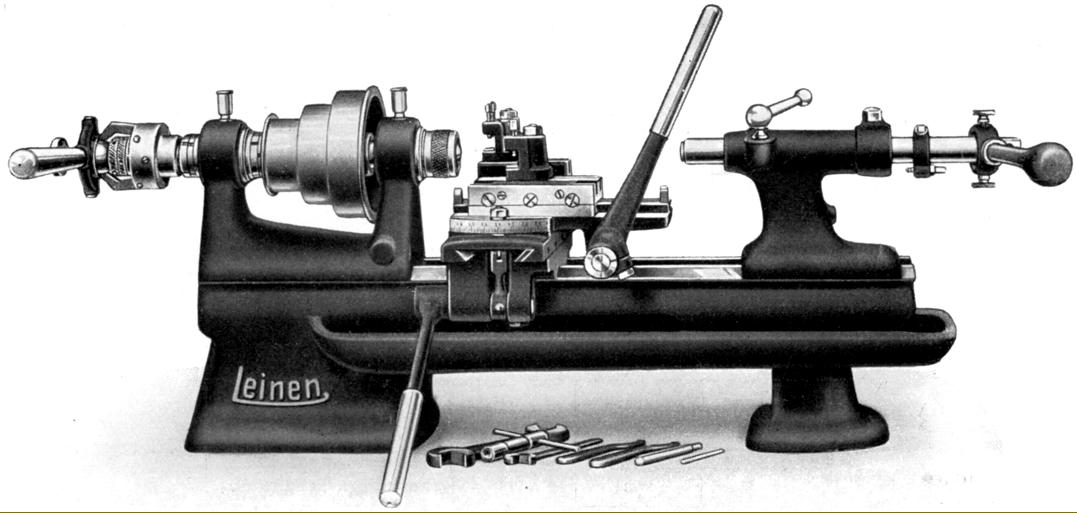
Precision backgeared lathes Types A-3-R, C-3-R, D-3-R, E-3-R and A-4-R. Shown with its standard equipment including two hand T-rests, collet draw-in attachment (and one collet), drive plate, male and female centres, compound slide rest, spanners and (no shown) the Type v6 countershaft with ring-oiled bearings and fast-and-loose pulley system.
|
|
|
|
|
|
|
|
 |
|
|
|
|
|
|
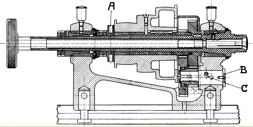
Apart from the Series A lathes, all others in the Leinen precision range from the 1920s and 1940s used a system where the speed-reducing backgear was clustered just inside the front headstock bearing. The bull wheel (the large gear on the spindle) was connected to and disengaged from the pulley by a collar at the left-hand end of the pulley and the gears engaged by a lever positioned immediate beneath the spindle line, a pin being used to lock into either the engaged or disengaged position. The same arrangement (less the locating pin) was also used on a number of cheaper lathes during the 1930 including the Myford Series ML1 to ML4 and in later years the ML7 and Super 7 where, in the case of the latter, it continues to this day.
|
|
|
|
|
|
|
|
 |
|
|
|
|
|
|
Lathes with simple thread-chasing attachment models: A3-P, B3-P, C3-P, D3-P E3-P and, with backgear and 1000 mm long beds as standard: A3-RP, C3-RP, D3-RP and E3-RP. Carried in a T-slot on the back of the bed the chasing unit was designed to kept clear of the compound slide rest and it was possible to use both together if necessary. Easily mounted and removed by two eccentric clamps, it could generate cylindrical or taper threads up to 25 mm (1-inch) long with an adjustable stop provided that incorporated an automatic, spring-assisted withdrawal mechanism - an ideal arrangement when machining up to a shoulder as it was unnecessary to stop or reverse the headstock spindle. The threading tool holder ran in ground V-slideways with adjustment by a micrometer-dial equipped thread with front and back stops - the arm carrying the holder being adjustable along a rod that ran for almost the full length of the bed. Thus, it was possible to arrange to thread almost any part of a component held between centres. Carried on the outboard part of the headstock spindle, the master thread was picked up by an arm pivoting from the end of the bed rod, just one follower being fitted to the arm at a time instead of the three to six "star" type offered by some other makers.
|
|
|
|
|
|
|
|
 |
|
|
|
|
|
|
Rear view of a lathes fitted with the simple version of the chase screwcutting attachment
|
|
|
|
|
|
|
|
 |
|
|
|
|
|
|
Lathes with a more complex system of chase screwcutting by changewheels Models: A3-PW, B3-PW, C3-PW, D3-PW E3-PW and, with backgear and 1000 mm long beds as standard: A3-RPW, C3-RPW, D3-RPW and E3-RPW. Identical in general arrangement to the simpler version offered by the makers, the changewheel-driven chasing attachment differed in having the master thread (or hob) supported on a separate shaft at the back of the headstock and being able to cut thread up to 75 mm (3 inches) in length. As the master thread was driven by changewheels it was possible, with the right gears in place (five were provided together with one hob), to economise on the selection of master threads stocked and use, for example, a coarse-pitch master to generate a number of different fine threads.
|
|
|
|
|
|
|
|
 |
|
|
|
|
|
|
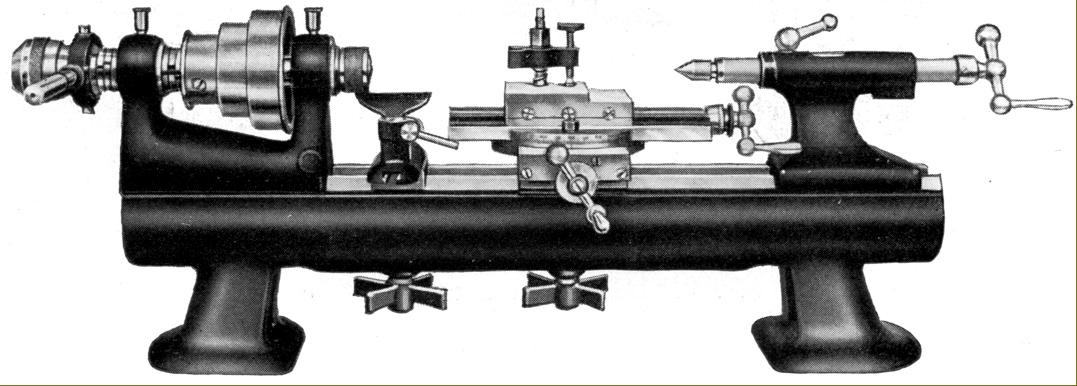
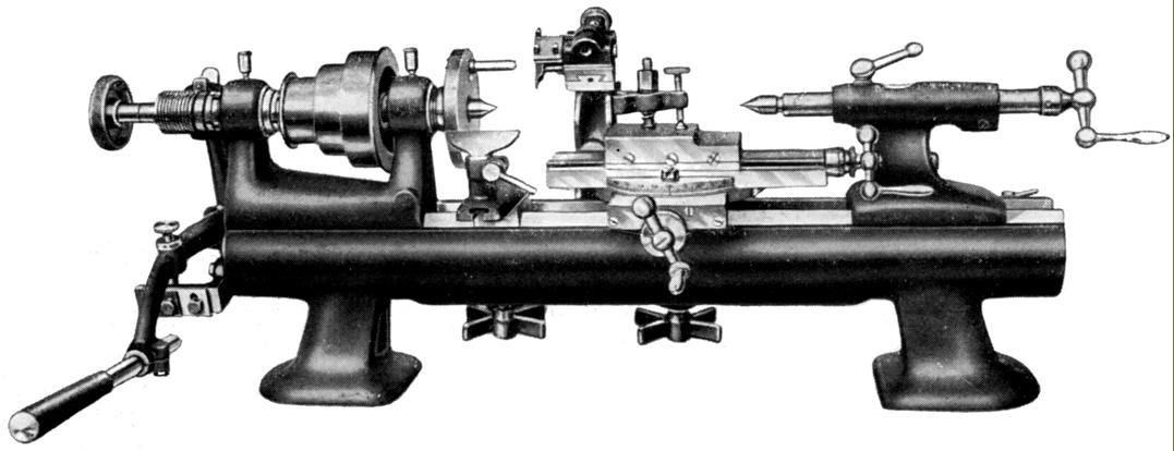
Front views of lathes with chase screwcutting by changewheels Models: A3-PW, B3-PW, C3-PW, D3-PW E3-PW and, with backgear and 1000 mm long beds as standard: A3-RPW, C3-RPW, D3-RPW and E3-RPW.
|
|
|
|
|
|
|
|
 |
|
|
|
|
|
|
Lathes with screwcutting by changewheels via a universally-jointed and sliding splined shaft system to the top slide. Models equipped with this facility were the: A3-G, B3-G, C3-G, D3-G and, with backgear and a 1000 mm long bed as standard: A3-RG, C3-AG and D3-AG. The unit, which could be fitted from new or owner-installed after purchase, included a proper tumble-reverse mechanism (to provide forward and reverse drive to the tool-slide and a neutral position), 14 changewheels (20, 35, 40, 45, 50, 55, 60, 65, 75, 90, 100, 120, 125 and 130) and a screwcutting chart. To drive the lathe the makers recommended the v7 countershaft with its ring-oiled bearings and double fast-and-loose pulley system that allowed an instant change between forward and reverse.
|
|
|
|
|
|
|
|
 |
|
|
|
|
|
|
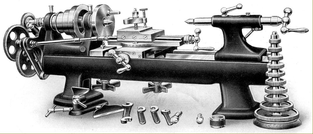
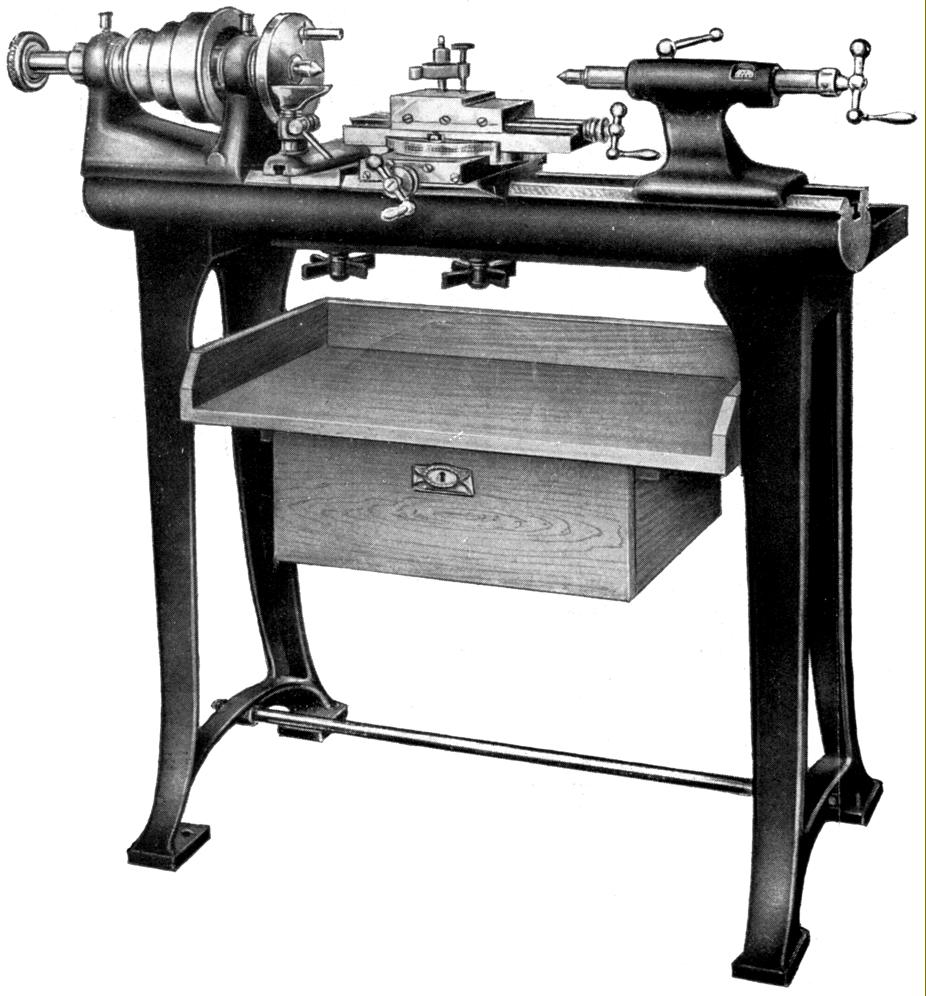
Precision plain lathe mounted on cast-iron legs with a wooden tool tray and locking storage cupboard. In this case, when factory supplied, the beds of all models were 1000 mm long - though the capacity between centres varied according to the particular model. Examples of the plain, non-backgeared type included the FA3, FB3, FC3, FD3, FE3, FA4 with backgeared versions designated FA3-R, FC3-R, FD3R, FE3-R and the FA4-R
|
|
|
|
|
|
|
|
|
|
|
|
|
|
 |
|
|
|
|
|
|
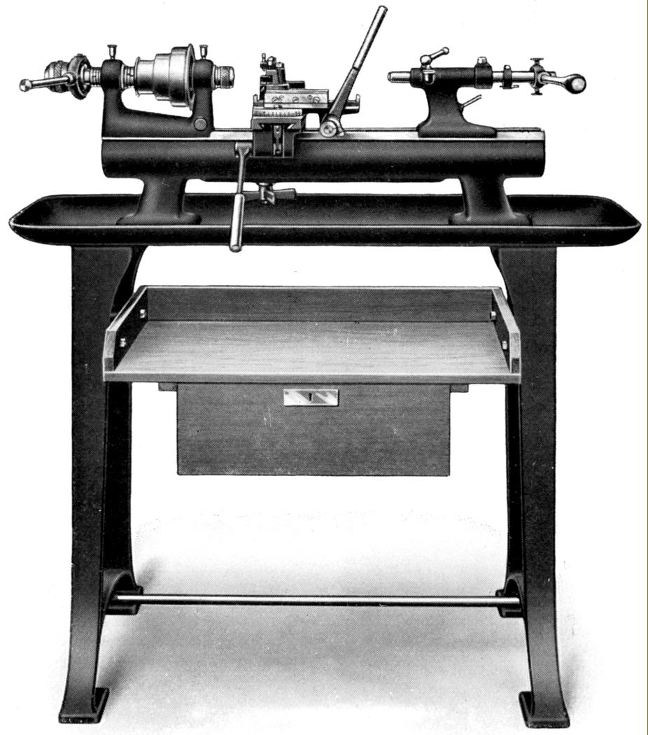
Plain lathe of the non-backgeared types stand mounted and fitted all-lever operation of the compound slide, collet closer and tailstock were designated the Types A3H and B3H-
|
|
|
|
|
|
|
|
 |
|
|
|
|
|
|
Top of the Leinen range during the 1920s and early 1930s were three lathes, the 100 mm centre height A3-LZ and the 130 mm C3-LZ and D3-LZ. All were of identical mechanical layout with a V and flat way bed, a leadscrew and changewheels for screwcutting, a separate powershaft with adjustable automatic disengage for the carriage sliding feed and a backgeared headstock holding a ground spindle running in adjustable bronze bearings and equipped to take draw-in collets. Both the A3-LZ and C3-LZ had a headstock spindle bored through 15 mm that took collets with a maximum through capacity of 8.5 mm - while the largest machine the range, the D3-LZ, had a much more massive headstock with a spindle hole of 25 mm and a through-collet capacity of 17.5 mm. The screwcutting drive passed through a conventional tumble-reverse mechanism and changewheels to a simple transfer gearbox that directed the drive to either leadscrew or powershaft. Twenty-one changewheels were provided: 20t, 25t, 30t, 35t, 40t, 45t, 50t, 55t, 60t, 65t, 70t, 75t, 80t, 85t, 90t, 95t, 100t, 120t, 125t, 130t and a 127t metric/English translation wheel.
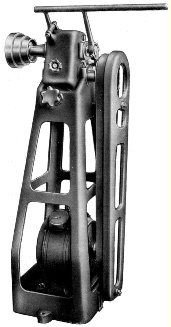
As on most similar lathes of the period, the drive system was not integrated into the lathe but arranged from a separate countershaft - in this case the makers recommending either the v7 with its ring-oiled bearings and double fast-and-loose pulley system that allowed an instant change between forward and reverse, or the remarkable (though heavily over-engineered) Types e1 and e2. Of this pair, the former consisted of a heavy (200 lb) cast-iron frame the lower section of which held a suitable motor (not provided) with the drive passing up to a pulley, held on a shaft that formed the hinge point of a swing head assembly. From the first shaft the drive passed upwards by a gear/clutch unit to ball-bearing supported shaft overhung on the left-hand end of which was the 3-step final drive pulley. The final drive belt was tensioned by a turnbuckle that moved the swing head to and fro and the drive instantly engaged or disengaged by a long horizontal bar that operated a clutch built into the upper shaft. On the e2 system, as far as can be ascertained, the same basic structure was used but with additional features built into the swing head, these though to be the addition of a reversing mechanism and some sort of double-acting clutch.
|
|
|
|
|
|
|
|
 |
|
|
|
|
|
|
A3-LZ and the 130 mm C3-LZ and D3-LZ as mounted on the maker's stand
|
|
|
|
|
|
|
|
 |
|
|
|
|
|
|
Type e1 self-contained cast-iron drive unit to mount behind a lathe. A relatively complex, 200 lb affair with a swing head countershaft, the unit incorporated a "quick coupling" operated by a horizontal bat through a toggle mechanism that allowed the spindle to be stopped and started while leaving the motor running. Another version, the e2, shown below, incorporated what the makers described as a "double coupling" that might have enabled an instant change to have been made from forward to reverse drive
|
|
|
|
|
|
|
|
 |
|
|
|
|
|
Type e2 drive with a "double coupling" - possibly to give an instant change from forward to reverse running
|
|
|
|
|
|
|
|
|
|
|
 |
|
|
|
|
|
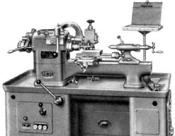
Polishing and Finishing Lathes (above the Type N3 and N4 finishing lathe)
Known in America as a "Speed" lathe these were lathe-based units designed as a piece of auxiliary equipment to assist in the completion or modification of work started on Capstan and other production machines. All had a centre height of 100 mm (4") and a bed 350 mm long (the Types T3 and T4 being the exception AT 650 mm). Two headstocks were offered, of the same type as used on the Company's conventional lathes, with a spindle bores of 15 or 25 mm and through-collet capacities of 8.5 and 17.5 mm respectively. All but the T3 and T4 consisted the headstock assembly cast integrally with a mounting foot together with a short bed extension that incorporated a water trough to allow the operator to cool tools that became overheated.
"Polishing" lathes, designated "P", were designed for light turning and polishing using hand T-rests in combination with various tools, files and emery cloth and employed either collets to hold smaller jobs or 3-jaw chucks for heavier. For speed of operation in a production shop, a special foot-operated collet opener could be specified, the collet being closed by a coil spring carried on the outer end of the headstock assembly - the work generally being entrusted to women or younger employees.
"Finishing" lathes, designated "N", were intended for heavier work and equipped with some form of lever-operated slide rest, either a simple cut-off or forming slide that moved across the bed or a full compound slide assembly, all being fitted with front and rear stops that allowed jobs to be set up and the machine operated by unskilled labour.
All types were recommended for use with the maker's v6 countershaft unit.
|
|
|
|
|
|
|
|
|
|
|
 |
|
|
|
|
|
|
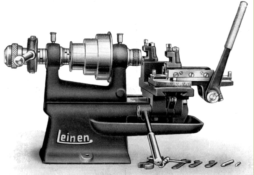
Finishing lathe Types N3H (15 mm spindle bore) and N4H (25 mm spindle bore) with compound slide and collet closer both of the lever-operated type
|
|
|
|
|
|
|
|
 |
|
|
|
|
|
|
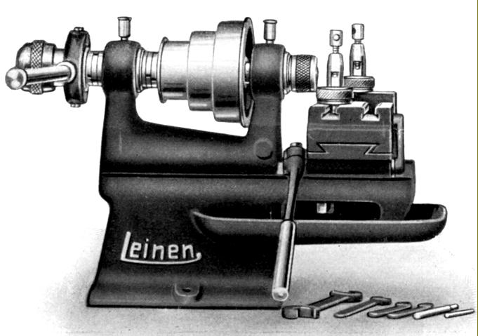
Polishing lathe Type P3 with foot-pedal collet opener and spring-assisted closer.
|
|
|
|
|
|
|
|
 |
|
|
|
|
|
|
Simple polishing lathe of the Types P3S (15 mm bore spindle) and P4S (25 mm bore spindle) with lever-operated collet closer and hand T-rest
|
|
|
|
|
|
|
|
 |
|
|
|
|
|
|
Types T3 (15 mm spindle bore) and T4 (25 mm spindle bore) finishing lathes with an extended, water-trough bed with headstock and tailstock-end feet and all-lever control of collet closer, compound slide rest and tailstock
|
|
|
|
|
|
|
|
 |
|
|
|
 |
|
|
|
|
|
|
|
|
|
Type ER 8T Precision Capstan Lathe of the 1950s.
The 2-speed motor drove via a two-step V pulley to provide two ranges of 4 speeds spanning 247 to 4900 rpm.
The lathe incorporated an automatic stock feed and a reversing reduction drive for thread cutting.
Another version, the ER6, was advertised as the "Instrument maker's high-precision hand-screw and second operation small turret lathe".
|
|
|
|
|
|
|
|
|
|
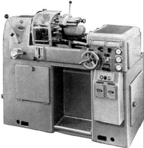
Type L4 RS EP of the 1950s. A production lathe equipped with (like the LZ screwcutting version) a single-pulley drive to the backgeared headstock from a two-speed clutched gearbox which gave ratios of 1 : 1 and 8 : 1. When used with the standard-fit 3-speed, three-phase motor twelve speeds were provided from either 13 to 1567 rev/min or 13 to 3135 revs/min The lathe was supplied fitted with a quick-action collet chuck, a Type w-31-st lever-operated compound slide rest and a Type r-3-a capstan-handle quick-action drilling tailstock.
|
|
|
|
|
|
|
|
|
|
|
|
 |
|
 |
|
|
|
|
|
|
|
|
Type R1 26 Precision Turret Lathe of the 1950s. This model was designed for the mass production of smaller components. The motor-drive system was different to other models based on the LZ screwcutting version, having a 3-step headstock pulley, single-speed motor, two-speed clutched gear change and backgear to give 12 speeds in the range 56 to 2240 rpm. A foot pedal reversed the direction of rotation.
|
|
|
|
|
|
|
|
|
|
Type J-26-HR and (below) LHR Second Operation Lathes of the 1950s.
These models were equipped with a quick-acting collet chuck and could be supplied, at extra cost, with either a simple foot-operated mechanical brake or an electro-mechanical laminated clutch - both of which stopped the spindle almost instantaneously.
|
|
|
|
|
|
|
|
|
|
|
|
 |
|
|
|
|
 |
|
|
|
|
|
|
|
3-step headstock pulley of the Type R1 26 production lathe of the 1950s
|
|
|
|
|
|
|
|
|
|
|
|
|
LHR Second Operation Lathe of the 1950s
|
|
|
|
|
|
|
|
 |
|
|
|
|
 |
|
|
|
|
|
|
|
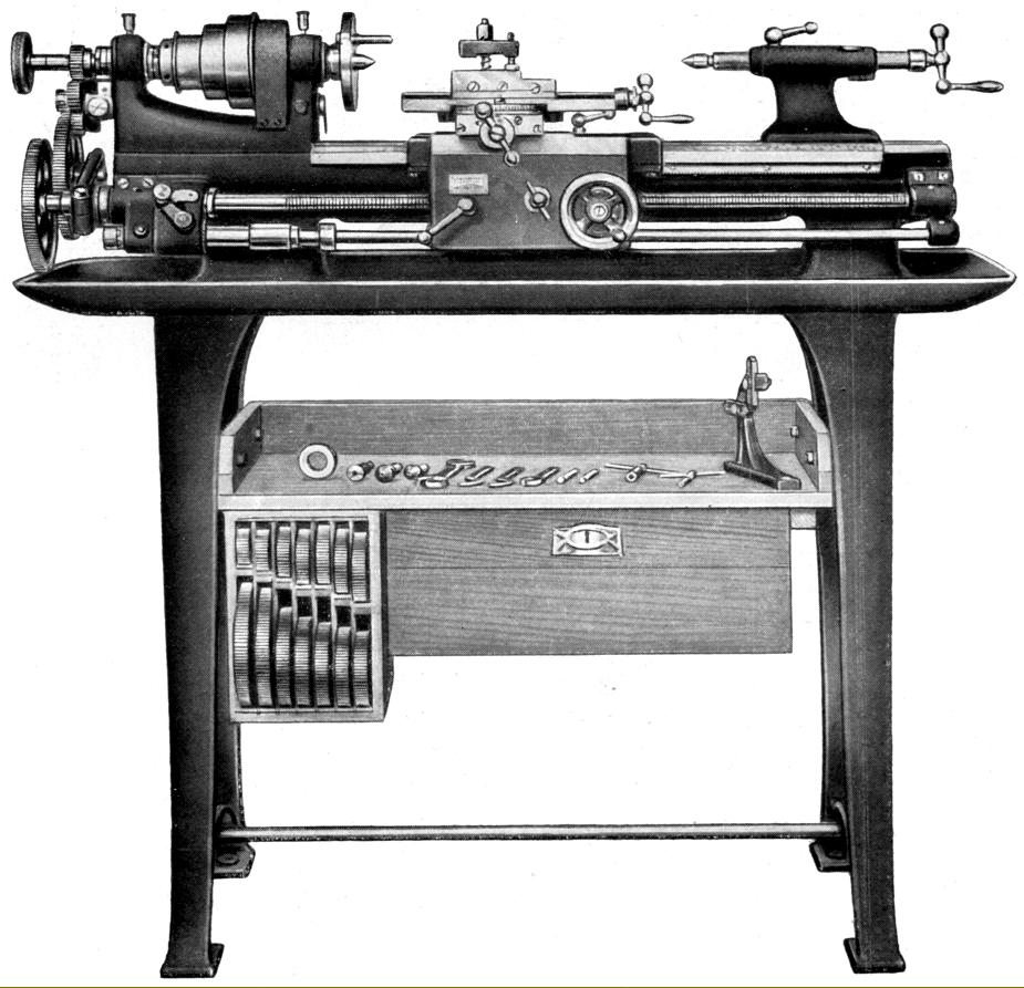
Type L3 Precision Plain-turning Lathe 100 mm x 320 mm of the 1950s. A traditional designed, super-accurate machine intended to compliment other more complex lathes in an experimental department or toolroom; a wide variety of accessories was available to expand its versatility. A six-speed drive was fitted with speed range of 460 to 2360 rpm.
|
|
|
|
|
|
|
|
|
|
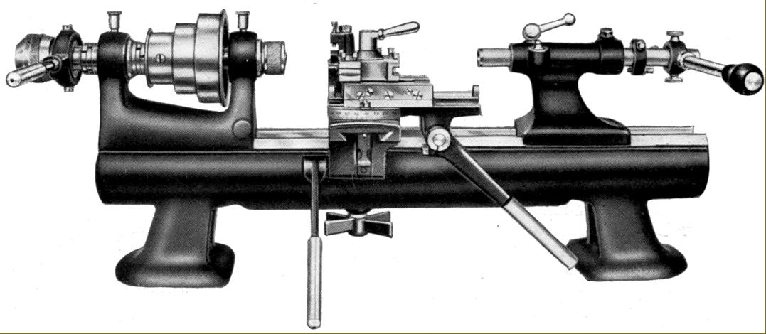
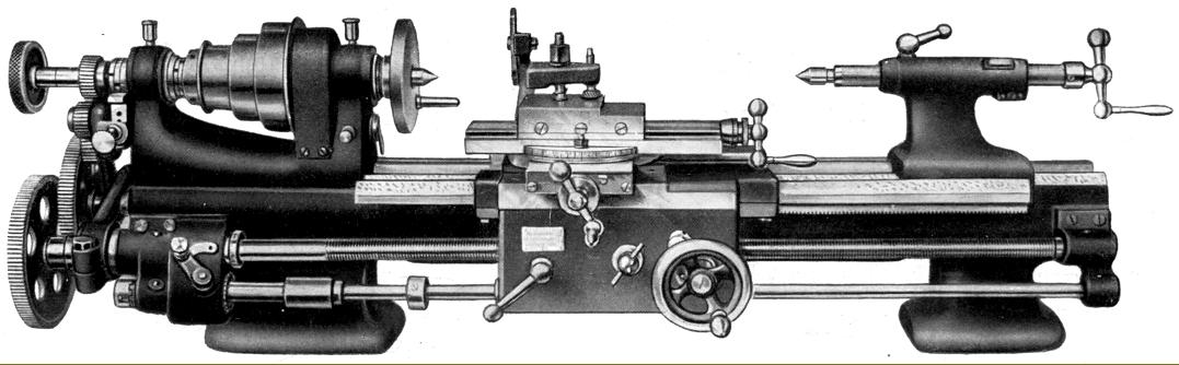
Type L4 RS Precision Plain-turning lathe of the 1950s. A heavy-duty version of the L3 with the centre height increased from 100 to 130 mm, the capacity between centres increased from 320 to 400 mm and fitted with a slow-speed backgear - the engagement lever can be seen on the front face of the headstock.
|
|
|
|
|
|
|
|
|
|
|
|
 |
|
|
|
|
 |
|
|
|
|
|
|
|
Type DM 3SE of the 1950s. This version of the L3 model was fitted with a thread chasing attachment. Details of how the system worked - as demonstrated on other precision lathes - can be found here
|
|
|
|
|
|
|
|
|
|
|
|
|
Leinen Leromat 36 High-speed Turret lathe of the 1950s with pre-selector control of the variable-speed spindle drive and feed rates
|
|
|
|
|
|
|
|
|
|
|
|
|
|
|
|