|
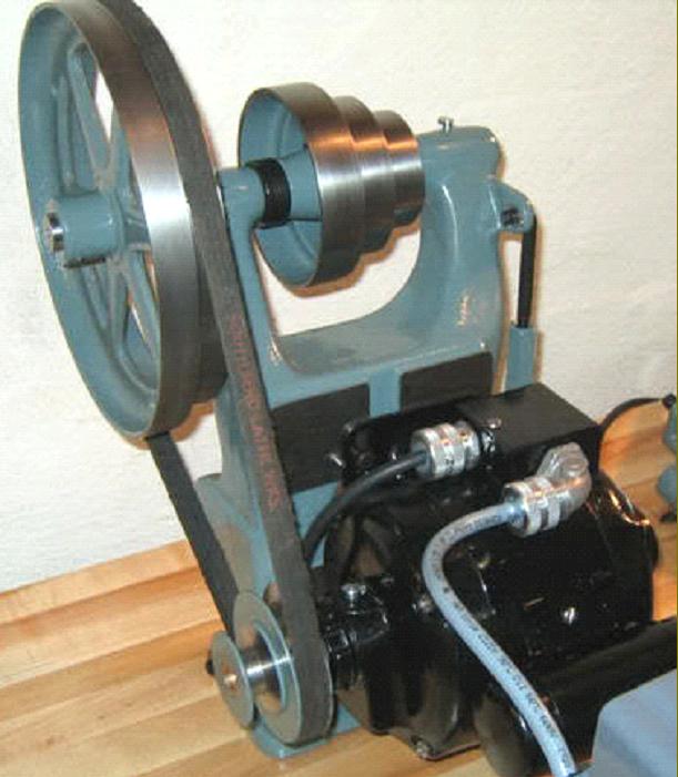
Lathes and other machine tools have, over many decades, being driven by all sorts of ingenious, complex and expensive means - yet the simplest and cheapest is almost the most effective - the "Countershaft" or "Jackshaft" system. Most small 1-phase motors in Britain and Europe (50Hz supply) spin at 1425 r.p.m., while those in the USA (Canada and some parts of Japan on 60 Hz supply) are usually marked a little faster at around 1600 to 1700 r.p.m. If the spindle of a metal-turning lathe (wood lathes are another matter) is driven directly from one of these motors, even using a small pulley on the motor shaft, and a larger one on the lathe, it would be revolving far too quickly for most jobs. Hence, it is necessary to introduce some way of both reducing and varying the speed - and that is the job of the countershaft. In a typical arrangement, illustrated below, the motor (with a small pulley on its spindle), is fastened to a vertical cast iron plate hinged at it base. Because the 1500 r.p.m. motor is driving a much larger pulley above it - in a ratio of something like 5 : 1 - the speed of the upper pulley is reduced to 300 r.p.m. (1500 divided by 5).
On the same shaft as the large countershaft pulley is a cone of pulleys - usually three or four of them, though occasionally two or five - and identical to those on the lathe spindle but arranged in the "reverse" order. If the middle pulley on the countershaft is made to drive the identically-sized pulley on the lathe spindle that too, of course, will turn at 300 r.p.m.. The pulleys each side of the centre are normally arranged to halve and double the speeds - hence the creation of speed set covering, for example, a useful 150 r.p.m., 300 r.p.m. and 600 r.p.m. However, if more speeds are required, it's a simple matter to fit both a small and a larger pulley side by side on the motor shaft together with two correspondingly larger pulleys side by side on the countershaft, and so double the number of available speeds. Or, the three-step pulley can be replaced with a four-step - so creating (together with a backgear system) a sixteen speed drive that, typically, would give a useful range starting at 25 and extending all the way up to a little over 2000 r.p.m.
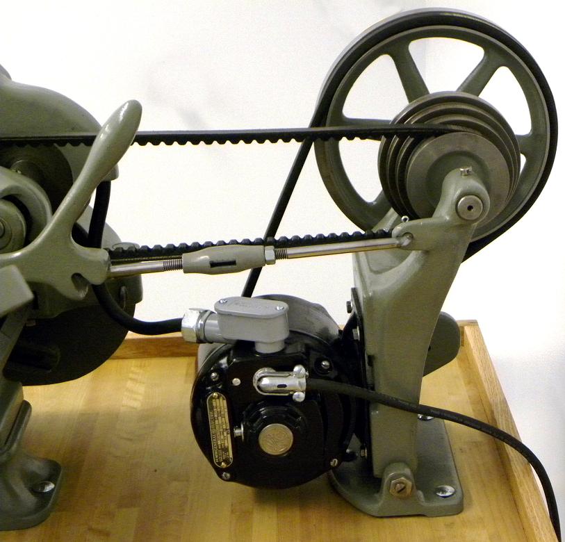
Some countershafts intended for the bottom end of the market had no means of attaching the motor to them, instead the motor was bolted to the bench, either behind the countershaft or between lathe and countershaft. Of those assemblies where the motor was attached to the countershaft some had a motor platform that allowed the belt tension between motor and countershaft to be adjusted - this being necessary when a 2-step pulley was fitted - while others had no form of adjustment at all, save perhaps for the motor feet (or mounting platform) being slotted to get the initial tension correct and make some small adjustment later as the belt stretched slightly in service.
One question that crops up frequently is, "I don't have a pulley on my motor. How big should it be ?" The real answer depends upon many factors but as a starting point for lathes up to 5-inches in centre height with plain bearings aim for a top speed of around 800 r.p.m. - and with roller bearings 1200 r.p.m. It may well be that higher speeds can be obtained safely, but it would be unwise to go beyond these levels as a starting point. To get a feel for the calculations needed first measure the diameter of the large pulley on the countershaft - say 10 inches. A 2-inch diameter pulley on the motor will give a reduction of 10 divided by 2 = a ratio of 5 : 1. Divide the motor speed (say 1425 r.p.m.) by 5 and the countershaft will be revolving at 285 r.p.m.. If the lathe has a 3-speed headstock pulley the next higher speed will be twice as fast (570 r.p.m.) and the one below half as fast (142 r.p.m.). This set is obviously a little slow so, increasing the motor pulley to 3-inches in diameter would give speeds of 214, 428 and 856 r.p.m.; that would be a better solution for, combined with the average 6:1 reduction backgear, it would produce a bottom speed of 36 r.p.m., handy for the turning of large diameters and also an deal rate for the inexperienced to use for screwcutting. If your countershaft pulley is a different diameter, simply substitute the appropriate measurements into the "equation" and experiment with different motor pulley sizes until you have as close a fit to the ideal as you can.
Today, with the availability of 1-phase to 3-phase "Inverters" (also known as VFDs for Variable Frequency Drive) it's possible to use a 3-phase motor to drive the spindle directly - the inverter being used to vary the speed. While this might not be a perfect solution it does have the advantage of being very easy to set up and, of course, simple and quick to change speeds. The best solution of all is a proper countershaft combined with inverter drive - this giving both ease of use and an incredibly wide speed range that can sometimes be arranged to start at 5 r.p.m. - handy for or the winding coil springs - up to 3000 r.p.m for polishing tiny diameters.
Hints and Tips for Making & Installing a Drive System
Pulley shafts are best supported in plumber blocks fitted with self-aligning ball races - these take up any slight differences in lever between the mounting points.
Flat-belt pulleys need to be both parallel with each other and aligned horizontally.
Most belt-drive machine tools have some sort of belt-tensioning mechanism - should it not then it's essential to find some way of managing this.
Methods include:
- slotting the motor-mounting plate or motor foot so that the assembly can be slid backwards and forwards
- make a hinged unit to carry the motor that allows it to be lifted up and down. Some sort of positive pusher rod is, however, essential to tension the belt; letting the weight of the motor add tension usually results in "bounce" as slight differences in pulley balance, motor shaft balance and belt thickness, etc., get into harmony.
- best of all - rig up a jockey pulley to press against the back of the belt as near to the motor pulley as you can
Before ordering a belt, don't just measure the old one and order the same dimensions, to get the correct length you'll need to ensure that:
- any jockey pulleys are slackened right off
- or the drive and driven pulleys are brought as close together as possible - then moved apart by about 10% of the available range.
- the screw-tension adjuster (or other device) is set to bring the two sets of pulleys as close together as possible and then set in its tensioned position
Measuring at this "shortest setting" will allow the maximum adjustment to be available to compensate for stretch as the belt settles in service.
For flat belts run a dressmakers' tape measure around them pulleys, or a length of tape that can then be laid flat on the bench to be measured.
It's often the case that a flat-belt drive system has been fitted with a belt that is two narrow; to find the correct size measure the width of the pulley and subtract 1/8" (3 mm). The wider the belt, the more effective the drive.
All belt drives - flat, V, round or toothed, etc. - should be tensioned by some form of positive lock or "push". Just relying on the weight of a motor to do the job will invariable cause "bounce" as the drive and driven pulleys are either never as perfectly round as they should be, or their mounting arrangements flexible in some way. Once bounce starts it can built up and shake the whole lathe or bench mounting in the most alarming way...
|
|