email: tony@lathes.co.uk
Home   Machine Tool Archive   Machine-tools Sale & Wanted
Machine Tool Manuals   Catalogues   Belts   Books  Accessories

Kärger DL-2 and an Unidentified Model from the late 1930s
- a photograph Essay -

Kärger Home Page  1950s Precision Kärger Type DL1
 
1930s Kärger Type DL2   1920s Screwcutting  DL Lathes
   
Karger Sliding-spindle Chase Screwcutting   Post WW2 Karger Lathes 

Precision Bench Karger   Restored  Kärgers

Karger Miller


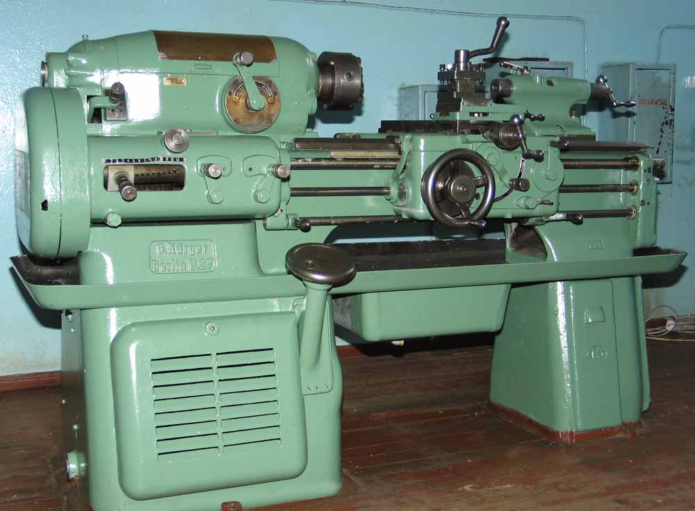
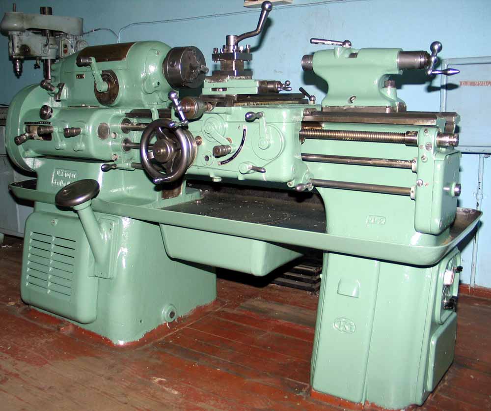
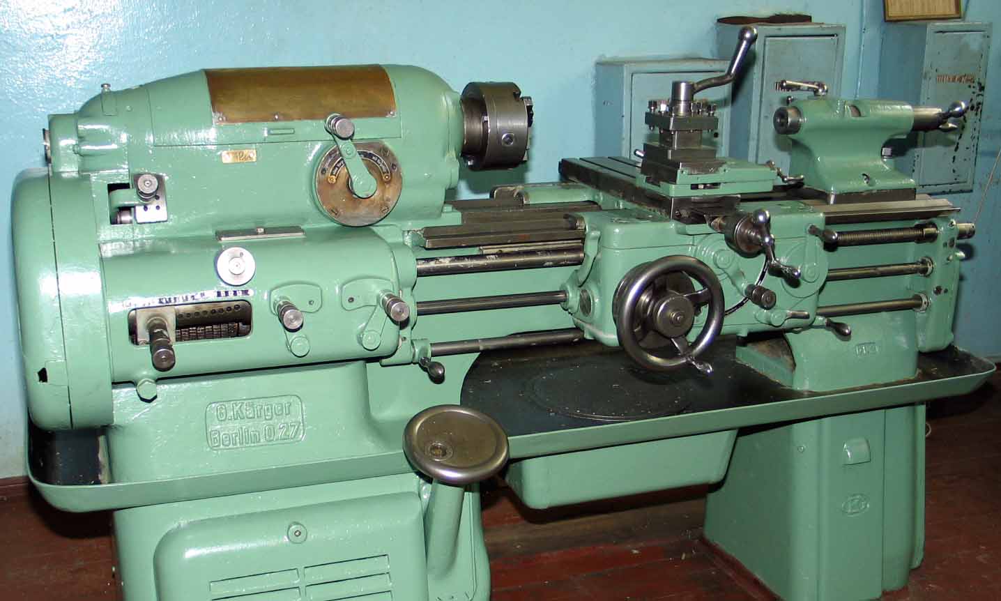
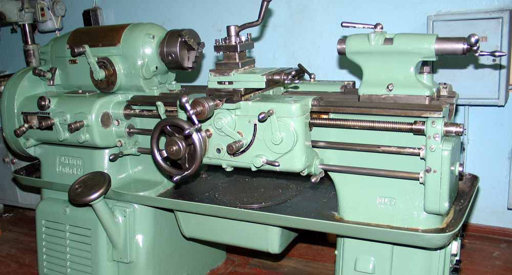
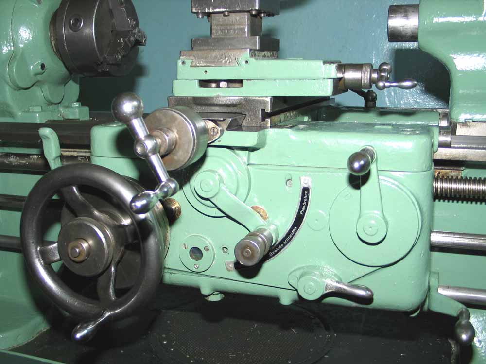
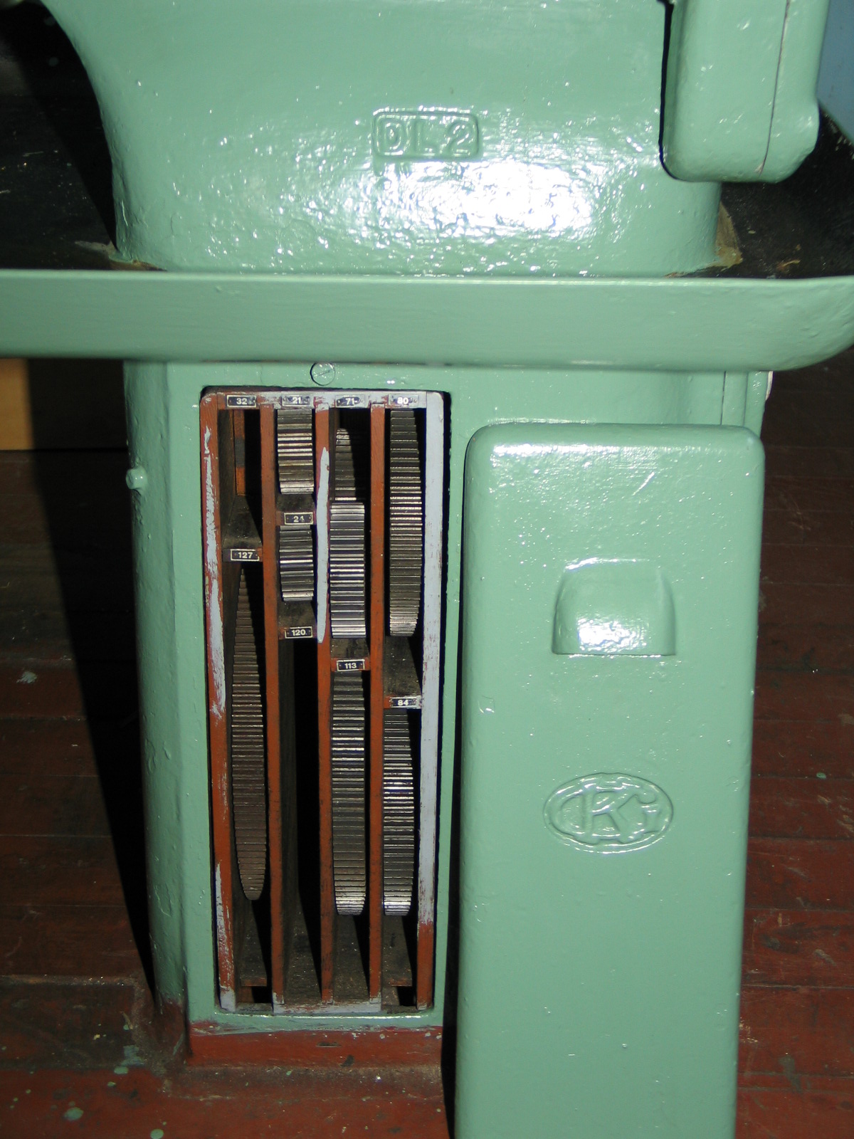
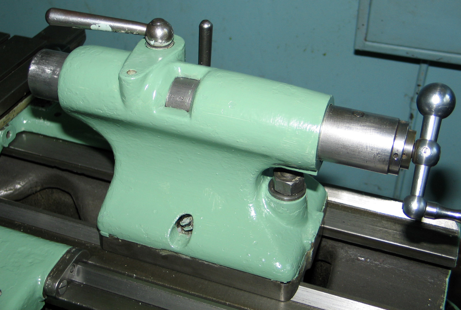
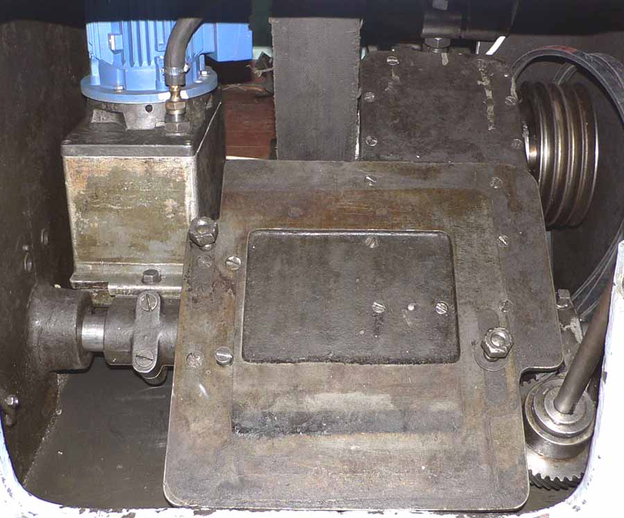
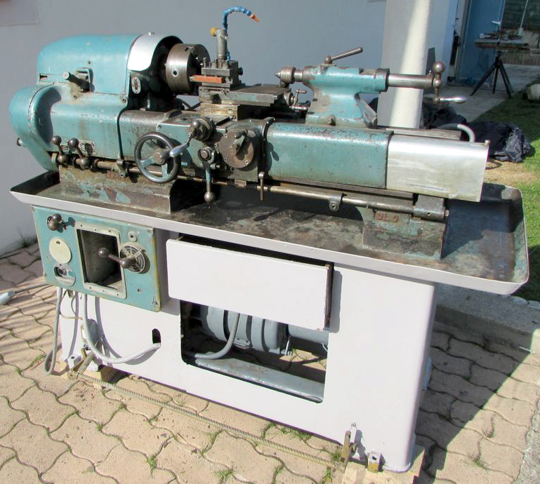
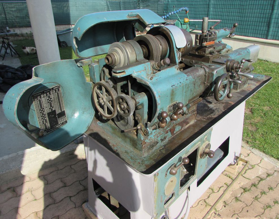
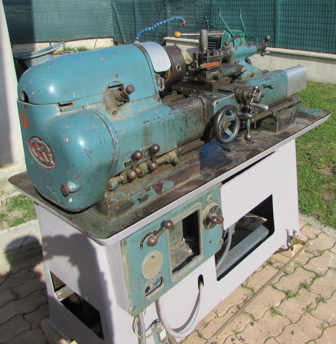
Displaying all the hallmark features of its maker, the 155 mm centre height by 1000 mm between centres DL-2 shown below was built in 1938 and seized by the Russians at the end of WW2. It eventually found its way to Latvia, where Sergey Kuznetsov and his friends restored it during 2006. The pictures bear close study - with several interesting mechanical features visible as well as evidence of  careful design and very high-quality manufacture. The finely-engineered controls that link the base-mounted spindle-speeds gearbox to its external circular selector handle are especially interesting.
Powered by a 1500 rpm 3.7 kW 3-phase motor (of Russian origin on the example illustrated) the initial drive was through 4 V-belts to a 6-speed speed-change gearbox lubricated by a centrifugal oil pump powered by a separate motor. The final drive was by a very wide, smooth-running flat belt to a pulley, supported in its own bearings, and driving the headstock spindle through a peg. The 12 spindle speeds, controlled by the well-established and safe "third-shaft" control system (with duplicated levers on the headstock and saddle), spanned a very useful 206 to 1200 r.p.m. in direct drive and down to 26 r.p.m. when the 8:1 reduction headstock-mounted backgears were engaged.
Able to generate, metric, inch, module and DP pitches, the oil-bath screwcutting gearbox was provided with an additional 13 changewheels to extend its threading range while the rate of longitudinal power feed went down to as low as 0.004 mm per revolution of the spindle. With the incorporation of several ingenious features the headstock held a spindle that had its drive pulley running in its own bearings (so relieving it of belt-pull strain) and a specially contrived backgear engagement mechanism. The pulley could be arranged so that it either drove the spindle, in the normal way, or be disengaged (from the spindle) and set to feed power down (from a gear on its left-hand end) to the screwcutting gearbox. This was achieved by including an interesting "double" tumble-reverse mechanism with two sets of gears each equipped with their own (parallel) plunger index locations. Those positions to the left (left-hand vertical set of plunger index locations) were employed for normal use (to transmit power to the screwcutting box when the spindle was turning) - the drive to the box being direct (in the usual way) through a gear train from the end of the spindle. In this situation disengaging the spindle from the pulley by setting the backgear engagement lever to its neutral position would also stop the screwcutting box. With the set on the right (right-hand set of plunger index locations) engaged, the drive to the box was direct from a gear fitted on the left-hand end of the pulley. In this case the spindle shaft could be independently disengaged from the pulley by switching the backgear engagement lever to neutral - yet this allowed the drive to the box to continue. In this way power could be fed to the saddle (with the spindle stopped) allowing it to act like a shaping machine or slotter and it was thus able, with suitable tooling, to cut metal held in a stationary chuck or bolted to a faceplate. In addition to these arrangements the backgear was arranged so that, when its engagement lever was put into neutral , the spindle stopped immediately - a handy set-up for thread cutting when the drive could be disengaged precisely at any point and without gearbox or motor inertia being involved.
Unusually for a large lathe the cross slide carried two long T-slots running from front to back (as used on some Emco lathes), a fitting that would have enabled the easy use of toolpost grinders, rear toolposts and a travelling steady.
Reflecting precision bench lathe practice not only was the (No. 3 Morse) taper barrel of the tailstock fully supported within the casting even when fully extended but the casting itself was cut away over the top to reveal the ruler graduations. Locked to the bed by the usual kind of over-centre clamp an additional clamping bolt was also provided, at the rear, for use in heavy drilling..


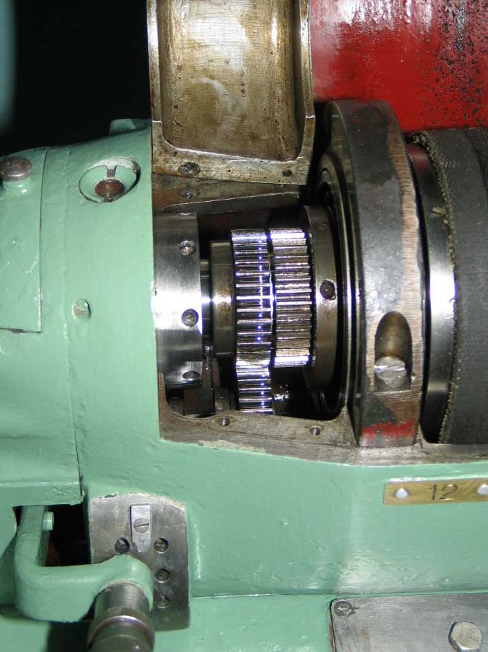
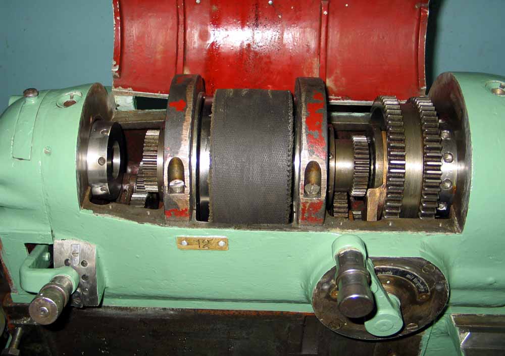
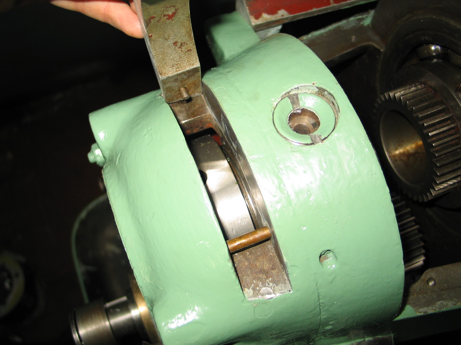
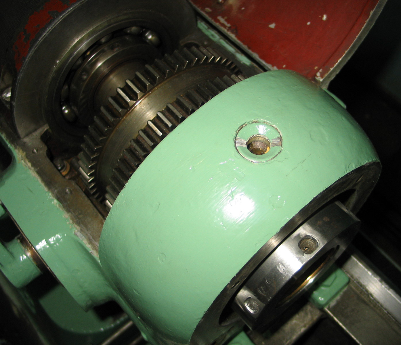
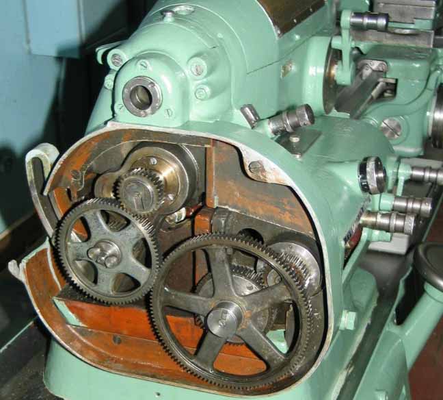
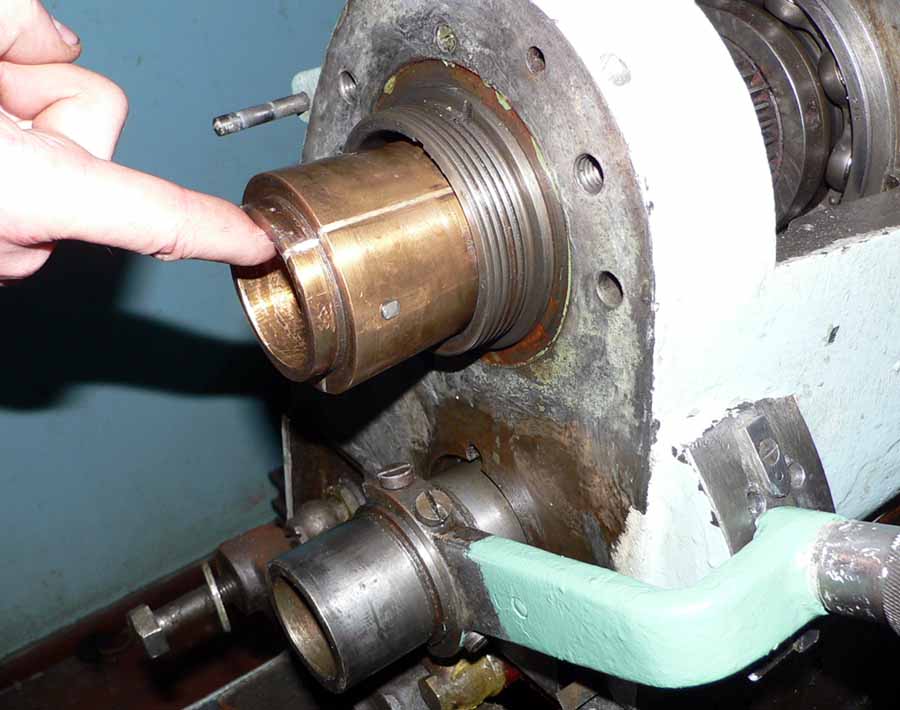
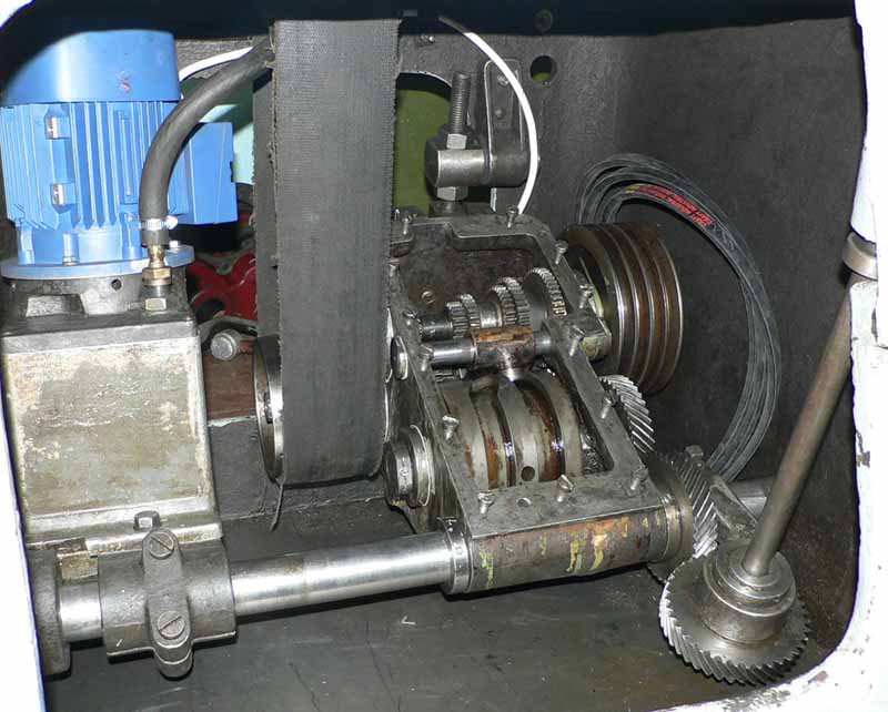
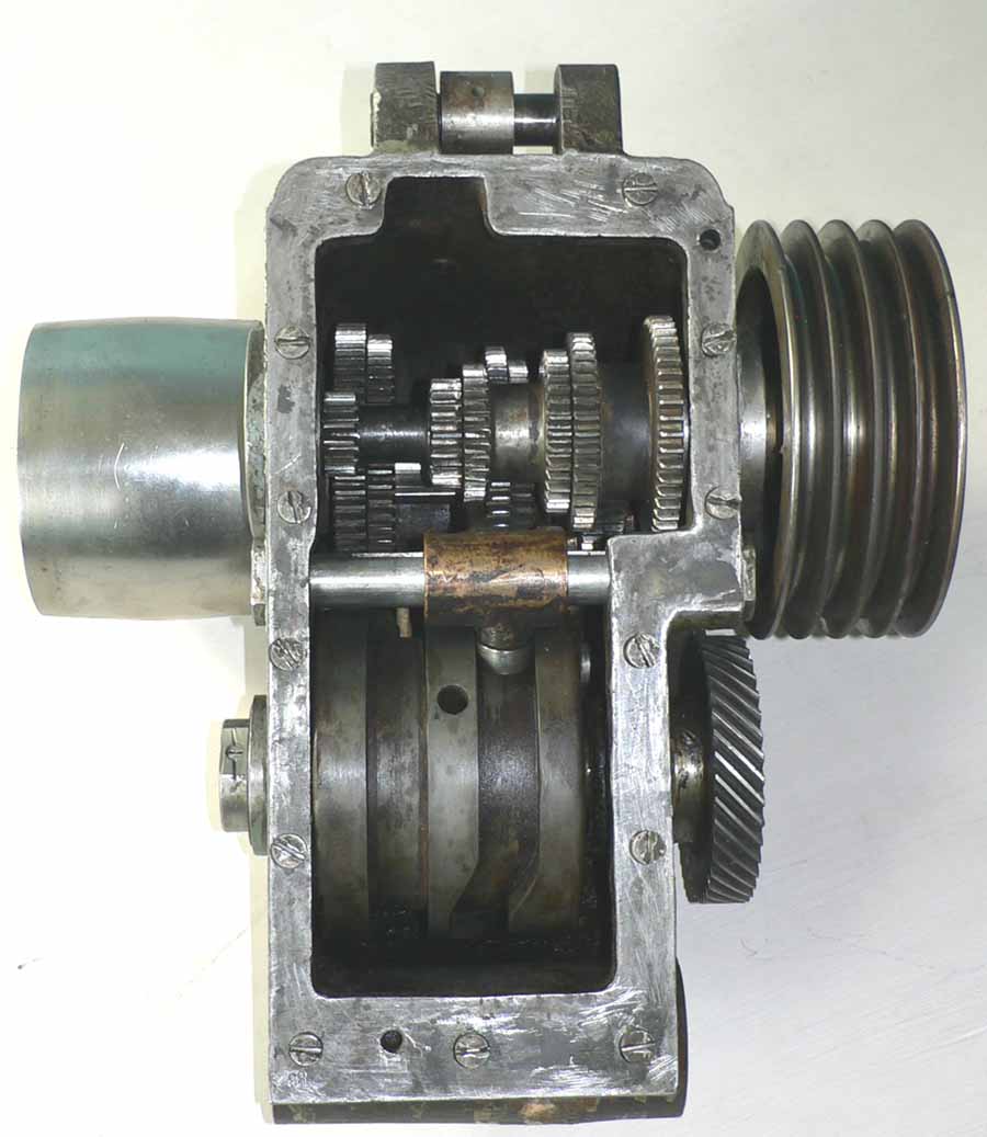
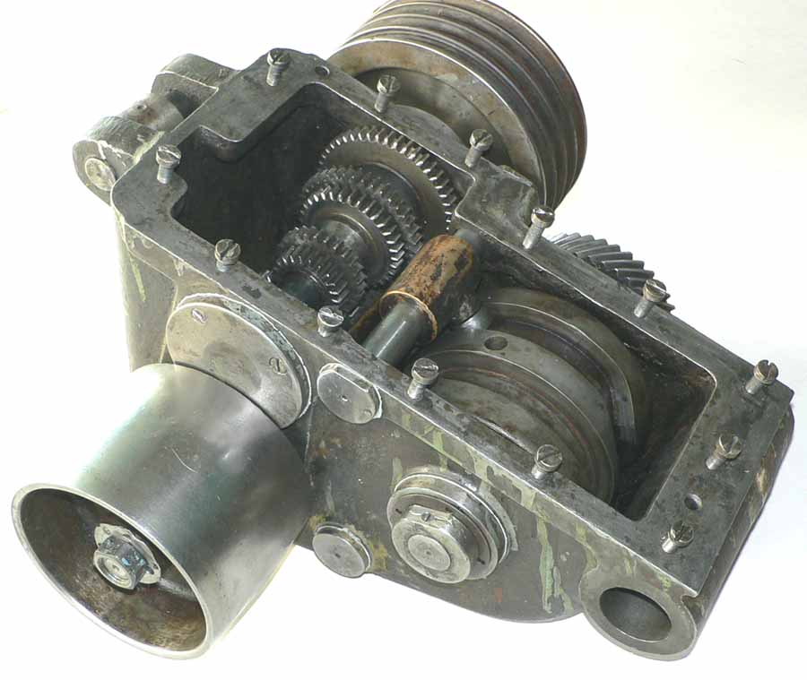
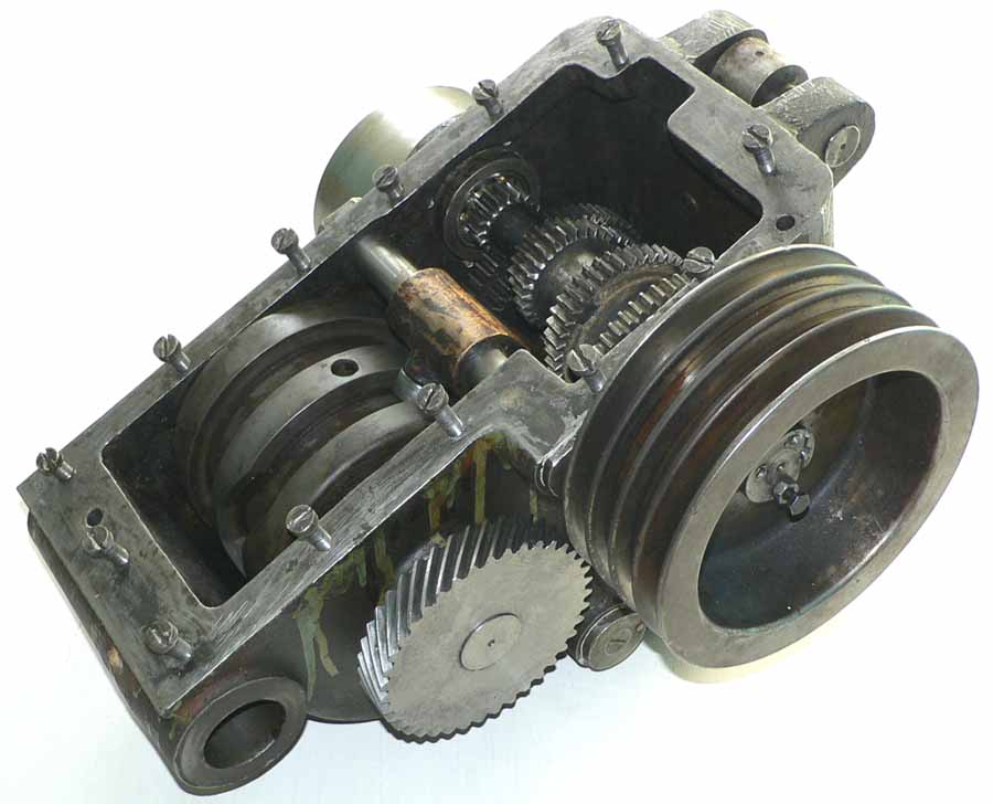
The unusual and clever system of transmitting power to the screwcutting and feeds gearbox was achieved by fitting a gear to the left-hand end of the independently supported headstock pulley (the gear to the right in this photograph). In this illustration the tumble-reverse mechanism is engaged with the gear to the left, so transmitting power down to the gearbox (in the usual way) with the spindle turning. With the pulley disengaged from the spindle, but still turning, the tumble assembly was moved across to the right to pick up the gear attached to the pulley.


The top of the spindle-speeds gearbox also acted as the motor-mounting plate


One of the last Industrial Karger lathes, this is an unidentified Model from the
late 1930s. After WW2 no more lathes of this class were built by the company


Kärger Home Page  1950s Precision Kärger Type DL1
 
1930s Kärger Type DL2   1920s Screwcutting  DL Lathes
   
Karger Sliding-spindle Chase Screwcutting   Post WW2 Karger Lathes 

Precision Bench Karger   Restored  Kärgers

Karger Miller

Kärger DL-2 and an Unidentified Model from the late 1930s
- a photograph Essay -
email: tony@lathes.co.uk
Home   Machine Tool Archive   Machine-tools Sale & Wanted
Machine Tool Manuals   Catalogues   Belts   Books  Accessories