 |
|
|
|
|
|
|
|
|
|
|
|
|
|
|
|
|
|
|
|
|
|
|
|
|
|
|
|
|
|
|
|
|
|
|
|
|
|
|
|
|
|
|
|
|
|
|
|
|
|
|
|
|
|
|
|
|
|
|
|
|
|
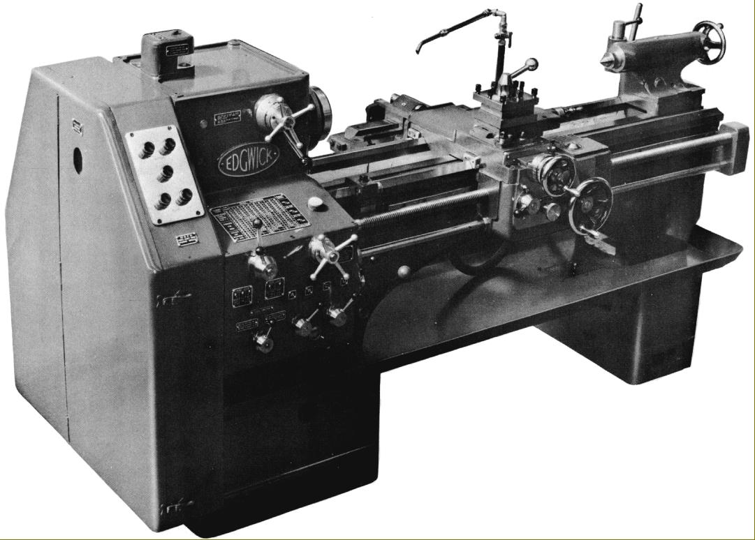
Manufactured from the early 1960s until late in the same decade the Edgwick "6.5-inch" centre height lathe was produced when the company was in the hands of the huge Coventry-based firm, Alfred Herbert Ltd. - at the time the world's largest grouping of machine-tool manufacturers and dealerships. Although some Mk. 1 versions of the Edgwick were marked: Made by George Swift & Sons Ltd. Halifax Exclusively for Alfred Herbert Ltd. Coventry (and the lathe was always factored through Herbert's distribution network) the Mk. 2 was built first at Herbert's Stratford factory and then, from 1962, at the Berridge works. Able to admit a generous 42 or, as a very long-bed version, 54 inches between centres (1066 or 1372 mm) the lathe was aimed at the medium-duty workshop and tool-room markets and launched against a number of well-established competitors including the best-selling Colchester Student and Master, the equally popular but slightly smaller Harrison "11-inch" and the less well-known but effective Churchill Cub Mk. 3. Against the opposition the Edgwick offered a number of advantages including a substantially heavier built (its longer bed helped it to weighed twice as much as the Student), a pump-lubricated instead of "splash" headstock, an oil-bath apron and, even with just a single speed motor, 12 spindle speeds.
A comprehensive redesign of an earlier model, the Company's 6.5-inch Mk. 1 (a lathe introduced in 1931 that sold, over a 30-year period, some 3,000 examples) the Mk. 2 was styled in a modern, angular way with a range of significant improvements that included: revised and easier-to-operate headstock and gearbox controls; larger spindle bearings; both headstock and tailstock Morse taper sizes increased (from No. 2 and No. 3 respectively) to a No. 4; an entirely different and totally-enclosed Norton-type quick-change screwcutting and feeds gearbox (though with the same number and range of pitches and feeds as before); a larger saddle; a shortened gap (to improve bed rigidity) and a slightly greater swing - the real centre height being 7 inches (178 mm). The result was a good-looking, effective machine that contrasted strongly with the decidedly dowdy, old-fashioned appearance of its forebear.
Continued below:
|
|
|
|
|
|
|
 |
|
|
|
|
|
Continued:
Cast in the company's own foundry the bed was mounted on separate headstock and tailstock plinths and braced by a multiple of cross ribs with V-shaped tops to aid the dispersal of swarf. It also featured a strong central arch section and traditional flat and V-ways provided to guide the carriage. A removable gap section was fitted as standard (even on the optional long-bed model) and, when lifted out, allowed a disc 22 inches in diameter and 7 inches thick to be machined on the faceplate. Unlike many such gap pieces, the one on the Edgwick was machined with a positive location, so aiding its speedy and accurate replacement.
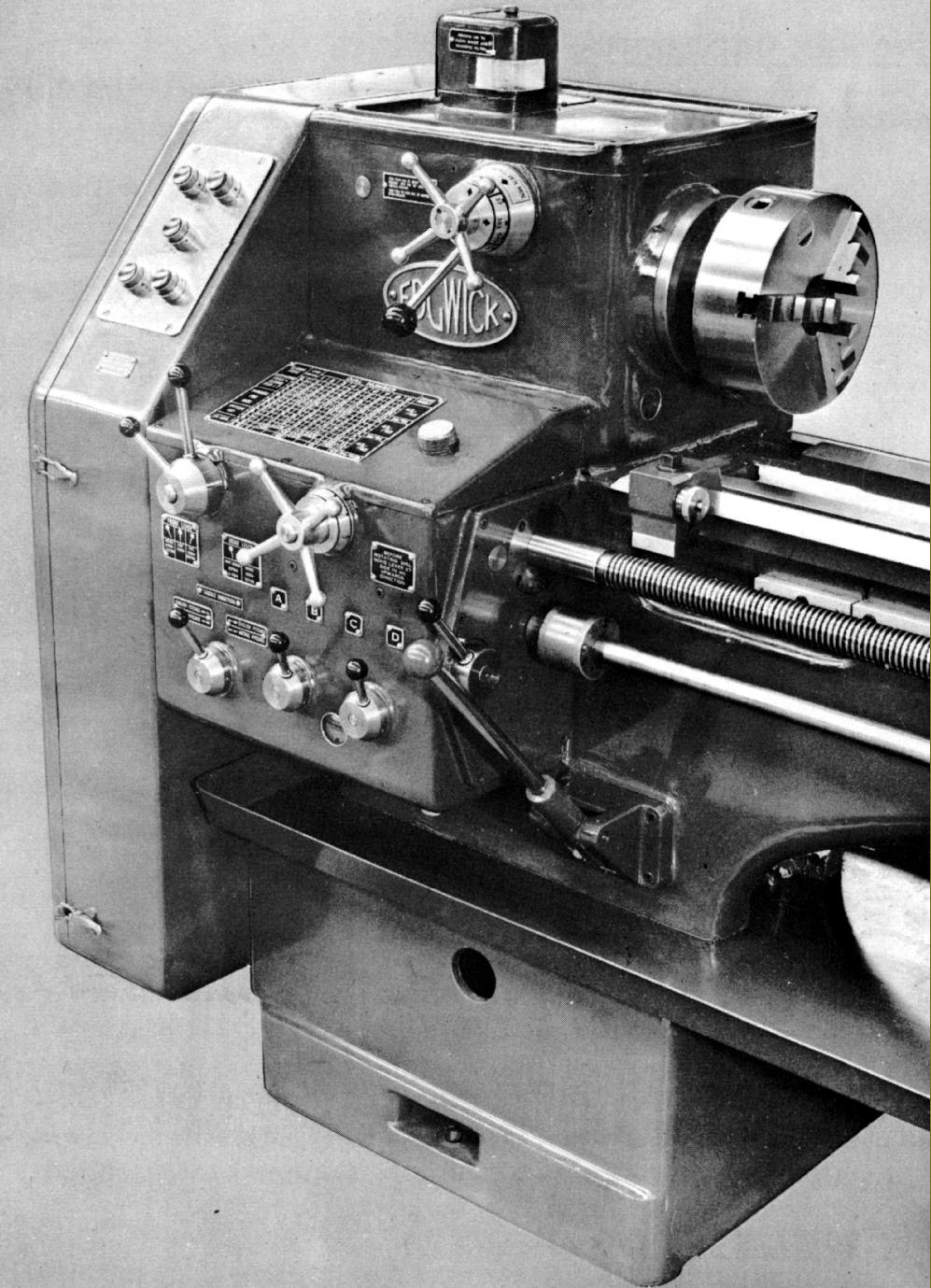
Sealed with a full-sized, bolt-on cap the rectangular-form headstock contained shafts running in ball races and gears made from heat-treated, nickel-chrome steel. The spindle, bored through a generous 1.75 inches (44 mm) with a 4 Morse taper, was machined from a 42-tons tensile forging and carried in large, pre-loaded tapered roller bearings. Unfortunately the spindle nose was not an industry standard type but formed with a bolt-on flange - three 17/32" holes on a 4.75-inch pitch-circle diameter - so making chuck replacement a slow and tedious business. 12 spindle speeds were available, controlled by the juxtaposition of a single lever and a star-shaped selector handle - their positioning moving sliding gears. The drive passed through an easily adjustable combined multi-disc clutch and brake unit of Herbert manufacture that was mounted on the first motion (input) shaft of the headstock - operation of the clutch to disengage the drive automatically bringing the brake into action. A substantial lever, hinged on a bracket bolted to the front of the bed in line with the end of the headstock spindle, controlled the clutch/brake unit. No safety interlock or gate was fitted and to engage the drive the lever was simply pulled outwards whilst to disengage it (and apply the brake) it was pushed inwards. Lubrication of the headstock was positive, by a self-contained plunger-type pump that forced oil through a gauze and magnetic filter unit mounted on top of the headstock. Fitted with a sight glass the assembly also allowed the operator to see, at a glance, that the system was functioning correctly. Drive to the headstock was by four "A" section V-belts from a motor mounted on two pairs of slide rails set at 90-degrees to each other on the back face of the headstock-end plinth. With both the width and height spacing of the mounting rails being adjustable this arrangement allowed, within reason, a motor of almost any make or configuration to be fitted. The maker recommended two motors: a 3 h.p. 960 r.p.m. or a 5 h.p. 1440 r.p.m. - the former giving spindle speeds of 17, 26, 38, 59, 112, 172, 190, 225, 290, 430 and 670 r.p.m and the latter 25, 39, 57, 88, 170, 255, 280, 380, 430, 580, 650 and 1000 r.p.m. Grouped together on a sloping panel on the left-hand side of the headstock's front face, the electrical controls consisted of just 5 easily reached push-buttons.
Continued below:
|
|
|
|
|
|
|
|
 |
|
|
|
|
|
|
Continued:
Available with either a 4 t.p.i. or 8 mm pitch leadscrew the lathe mounted a totally-enclosed screwcutting and feeds gearbox that held solid, 6-spline shafts running on ball races with lubrication by splash from an oil bath with a sight-glass level window. Although completely redesigned, the box gave exactly the same number of feeds and pitches as the box on the Mk. 1 i.e. with an inch leadscrew and a 45t/45t gear pair in place on the changewheel bracket, thirty-six sliding and surfacing speeds, thirty-six English pitches and thirty-four metric could be obtained from one setting of the standard gear train. English pitches ran from 2 to 28 t.p.i and metric from 1.25 to 14 mm However, this range could be extended, by the substitution of a 30t/60t changewheel pair, to produce a range of finer pitches and feeds - nine English from 32 to 56 t.p.i. and four metric from 0.5 to 0.875 mm All screwcutting pitch and feed-selection rates were by simple rotary controls or levers, there being no conventional tumbler assembly fitted. A thread-dial indicator was built in to the front right-hand saddle wing and supplied as part of the lathe's ordinary equipment.
Power sliding feed rates ran as fine as what Edgwick engagingly termed "400 cuts per inch" (0.0025 inches of cut per revolution of the headstock spindle) with the optional fine-feed changewheels in place. As on many other lathes the rate of power cross feed was set to be twice as fine and so gave, at the slowest rate, "800 cuts per inch" - equal to tool-advance rate of 0.00175 inches per revolution of the spindle.
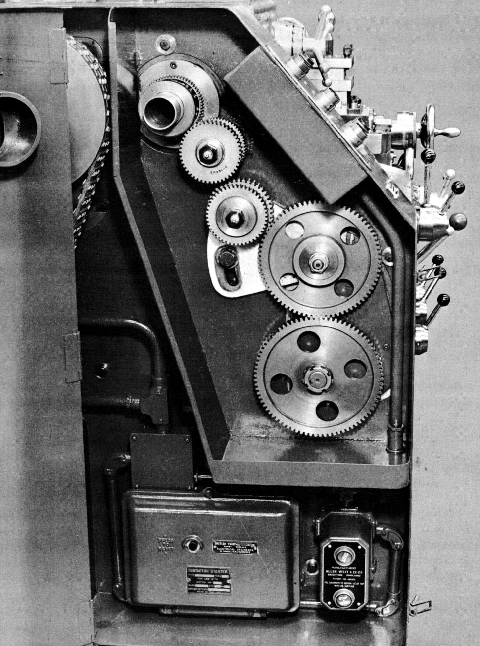
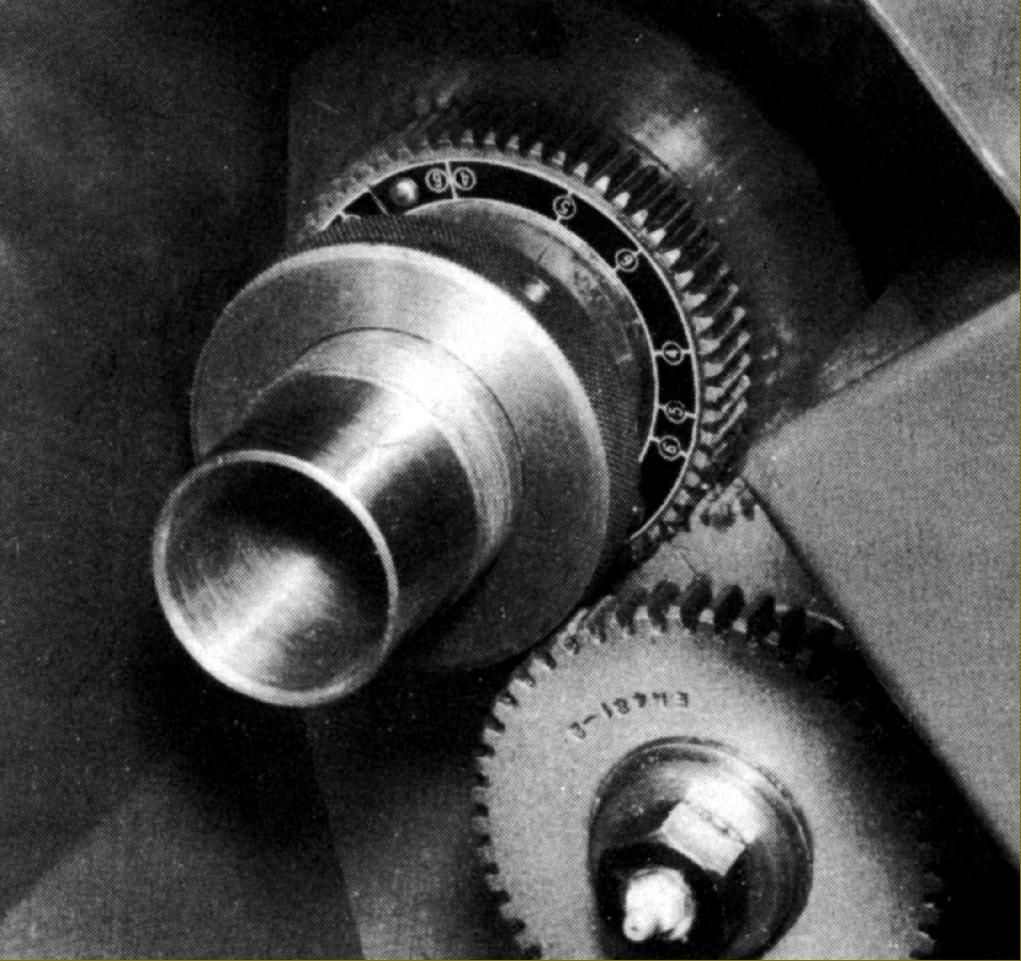
Knowing that the lathe was intended for professional rather than training use, the makers included markings to assist in the cutting of threads with 2, 3, 4 and 5 starts. The marks were inscribed on an annular plate, attached to the gear on the end of the headstock spindle, and showed the tooth spacing to be used for the first thread of 4, 6 and 8 starts. To obtain a 2-start thread the second thread was cut when the index tooth came opposite the first-start position whilst for 3-start threads alterative divisions marked for 6 starts could be used. The gear immediately below - on the second-motion shaft - was engraved with an arrow by which means the operator could cut the first thread with the arrow against the appropriate mark and then, for subsequent starts, withdraw the graduated gear, turn the spindle until the mark for the next start came opposite the index tooth, then re-engage the gear on the spindle.
Continued below:
|
|
|
|
|
|
|
|
|
|
|
|
|
|
 |
|
|
|
|
|
|
Continued:
Unlike the aprons of its direct British-market competitors that on the Edgwick rejoiced in oil-bath lubrication with a (manually-operated) two-way, spring-loaded plunger pump that lifted oil into a distribution tray from where it was carried by wicks to the various parts of the mechanism. A quantity of oil was also bled off to lubricate the bed, whose ways were protected by neoprene wipers. Power sliding and surfacing feeds were driven by a separate feed shaft from the screwcutting gearbox and both selected and engaged by a simple push/pull button - an arrangement inferior to that on most Harrison lathes where feed engagement was provided by a separate lever with an absolutely positive snap in-and-out action. The power-feed take-off passed though a safety clutch that slipped automatically a pre-set loading.
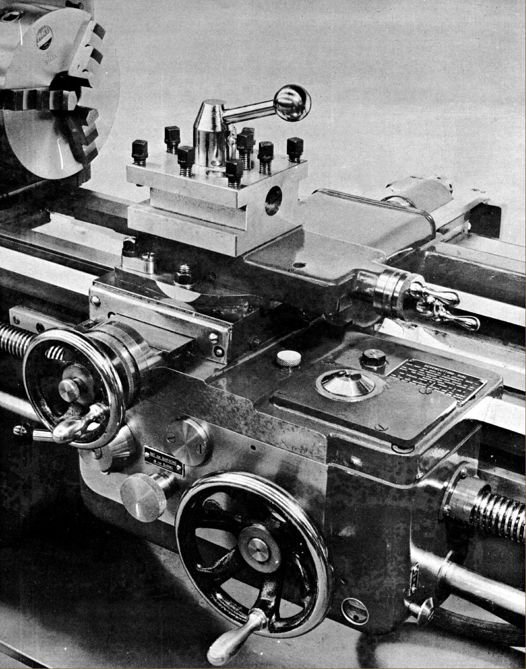
Cross and top slides were entirely conventional, with the former having a full-circle handwheel and the top slide a traditional two-finger grip that allowed very precise manipulation of the feed on delicate jobs. The micrometer dials zeroed, with that on the cross slide being of a decent size with particularly clear engravings. As a taper-turning unit was an accessory (and required room to mount) the cross slide was of the "short" variety with two inherent disadvantages: less support for the top slide and a concentration of wear in the central part of its ways. However, Edgwick did provide one unusual and very handy fitting, a device that secured the top slide exactly parallel to the bed ways. Positioned to the left-hand front side of the slide the unit consisted of a hardened plunger that passed though accurate bushings in the base of the top slide and the cross slide. A swivelling latch was used to hold the plunger out of engagement but when, for boring or other parallel work, it was necessary to have the tool in alignment with the headstock spindle, the latch could be swung out and the plunger pressed down.
Although various optional toolposts were offered, including 4-way and American single types, the standard fitting was a well-made and robust square turret with three sides milled to take rectangular-sided tools and the fourth bored 1.25" to accept round fittings such as boring tools and reamer and drill holders. A hardened plunger, running through hardened bushes, located the post, the whole unit being spring mounted so that, upon slackening the locking handle, the block was lifted and could be rotated to a new position.
Of substantial construction, the tailstock carried a No. 4 Morse taper barrel - when a No. 3 might have been expected - and could be set over for the turning of shallow tapers. An attached lever, operating a simple cam-form cross bar that pulled on an eye-bolt, locked the tailstock to the bed - no self-hiding loose spanners to waste the time of the Edgwick operator.
Supplied with the lathe as part pf the standard equipment was a 3-way toolpost, one 7-inch driver plate, one 12-inch faceplate, two No. 4 Morse taper centres, a grease gun and the necessary spanners..
|
|
|
|
|
|
|
|
 |
|
|
|
|
|
|
|
|
|
|
|
 |
|
|
|
|
|
|
Markings to aid the cutting of multi-start threads
|
|
|
|
|
|
|
|
 |
|
|
|
|
|
|
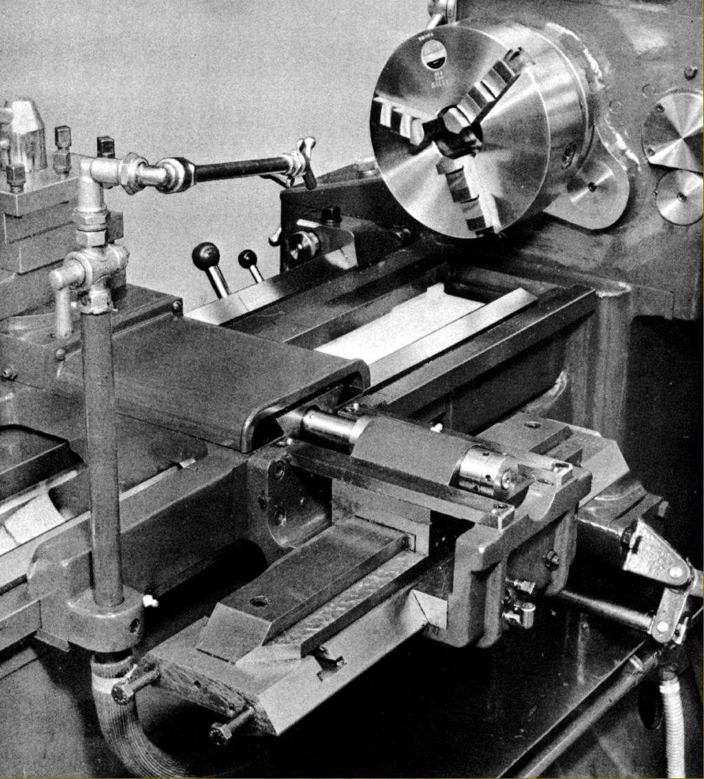
Optional taper-turning attachment
|
|
|
|
|
|
|
|
 |
|
|
|
|
|
|
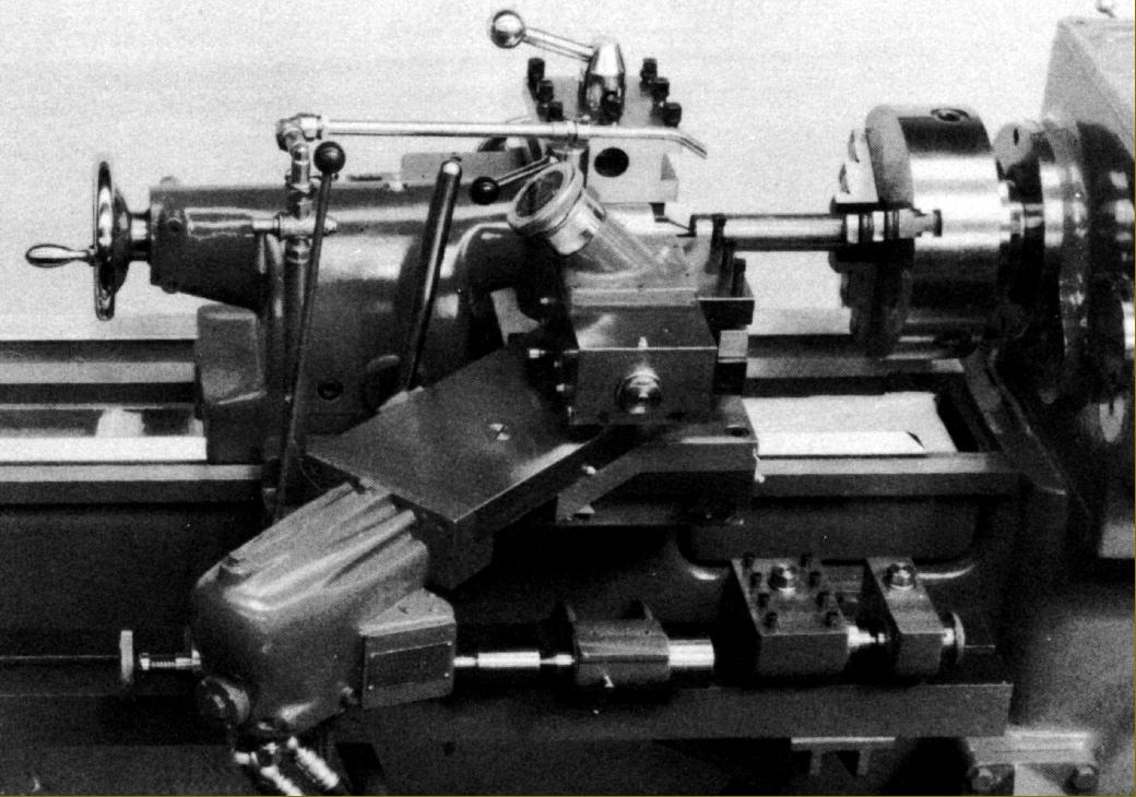
Hydraulic copying attachment
|
|
|
|
|
|
|
|
|
|
|
|
|
|
|
|