 |
|
|
|
|
|
|
|
|
|
|
|
|
|
|
|
|
|
|
|
|
|
|
|
|
|
|
|
|
|
|
|
|
|
|
|
|
|
|
|
|
|
|
|
|
|
|
|
|
|
|
|
|
|
|
|
|
|
|
|
|
|
|
|
|
|
|
|
|
|
|
|
|
|
|
|
|
|
|
|
|
|
|
|
|
|
|
|
|
|
|
|
|
|
|
|
|
|
Now comparatively rare, the Mk. 1 Edgwick 6.5-inch lathe was manufactured for a surprisingly long time, from the early 1930s until the late 1950s or early 1960s - when it was superceded by the heavily revised Mk. 2. The lathe was aimed at the medium-duty workshop and tool-room markets and launched against a number of well-established competitors including the early 6 and 7-inch geared-headstock Colchester types, the early Harrison models and the first versions of the Churchill Cub.
Cast in the company's own foundry the bed was mounted on separate headstock and tailstock plinths and braced by a multiple of cross ribs with V-shaped tops to aid the dispersal of swarf. It also featured a strong central arch section (a design that mirrored contemporary English practice of the 1930s) and traditional flat and V-ways provided to guide the carriage. A removable gap section was fitted as standard (even on the optional long-bed model) and, when lifted out, allowed a disc 20 inches in diameter and 5 inches thick to be machined on the faceplate. Unlike many such gap pieces, the one on the Edgwick was machined with a positive location, so aiding its speedy and accurate replacement.
Headstock and drive system:
Sealed with a full-sized, bolt-on cap the rectangular-form headstock contained shafts running in ball races and gears made from heat-treated nickel-chrome steel. The spindle, bored through a generous 1.75 inches (44 mm) with a sleeve to take it down to a 2 Morse taper, was machined from a 42-tons tensile forging and carried in large, pre-loaded tapered roller bearings. Unfortunately the spindle nose was not an industry standard type but formed with a bolt-on flange - three 17/32" holes on a 4.75-inch pitch-circle diameter - so making chuck replacement a slow and tedious business. 12 spindle speeds were available, controlled by the juxtaposition of two concentrically mounted levers on the front face of the headstock. The drive passed through an easily adjustable multi-disc clutch and brake unit of Herbert manufacture fitted inside the first motion (input) shaft of the headstock - operation of the clutch to disengage the drive automatically bringing the brake into action. On early versions the clutch/brake-operating lever protruded through the front face of the headstock (to the left of the spindle-speed levers) but on later models was fitted in a rather more easily-reached position on a boss formed on the face of the bed immediately below the spindle nose. As was common at the time, no safety interlock or gate was fitted to either set of levers. Lubrication of the headstock was by splash, the oil level being checked through a sight-glass window. Drive to the headstock could be by either a 3-inch wide flat belt (from overhead line shafting or a wall-or ceiling mounted countershaft) or by four "A" section V-belts from a motor mounted on two pairs of adjustable slide rails set at 90-degrees to each other on the back face of the headstock-end plinth (the arrangement allowing almost any variety of motor to be accommodated). With both the width and height spacing of the mounting rails being adjustable, this arrangement allowed, within reason, a motor of almost any make or configuration to be fitted - but the makers offering to fit either a 3 h.p. 955 r.p.m. or 5 h.p. 1440 r.p.m. motor. Both could be non-reverse or reverse with, in the former case, two push buttons for start and stop and in the latter three for start, stop and reverse.
Continued below:
|
|
|
|
|
|
|
|
 |
|
|
|
|
|
|
|
|
|
|
|
|
|
|
|
Continued:
Screwcutting and power feeds:
Built both with and without screwcutting - the latter version seldom found and intended for simplified production work - the former was offered a choice of a 4 t.p.i. or 8 mm pitch leadscrew while the screwcutting and feeds gearbox held solid, 6-spline shafts running on ball races and was lubricated by splash from an oil bath quipped a sight-level window. With an inch leadscrew, and a 45t/45t gear pair in place on the changewheel bracket, the box gave thirty-six sliding and surfacing speeds, thirty-six English pitches and thirty-four metric from one setting of the standard gear train English pitches ran from 2 to 28 t.p.i and metric from 1.25 to 14 mm - though these could be extended, by the substitution of a 30t/60t changewheel pair, to produce a range of finer pitches and feeds - nine English from 32 to 56 t.p.i. and four metric from 0.5 to 0.875 mm. However, this range could be extended, by the substitution of a 30t/60t changewheel pair, to produce a range of finer pitches and feeds - nine English from 32 to 56 t.p.i. and four metric from 0.5 to 0.875 mm When fitted with the 8 mm leadscrew thirty-four metric pitches from 0.75 to 14 mm could be cut and 36 inch from 2 to 28 t.p.i. One important caveat concerned the gearbox selection lever for it was possible to set one for inch and the other for metric threads - a situation that did not cause any mechanical damage but, naturally, gave an incorrect pitch result. A thread-dial indicator was built in to the front right-hand saddle wing and supplied as part of the lathe's ordinary equipment.
Power sliding feed rates ran as fine as what Edgwick engagingly termed "400 cuts per inch" (0.0025 inches of cut per revolution of the headstock spindle) with the optional fine-feed changewheels in place. As on many other lathes the rate of power cross feed was set to be twice as fine and so gave, at the slowest rate, "800 cuts per inch" - equal to tool-advance rate of 0.00175 inches per revolution of the spindle.
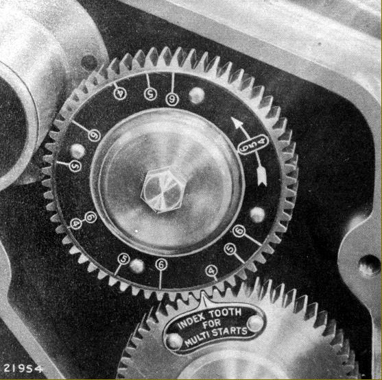
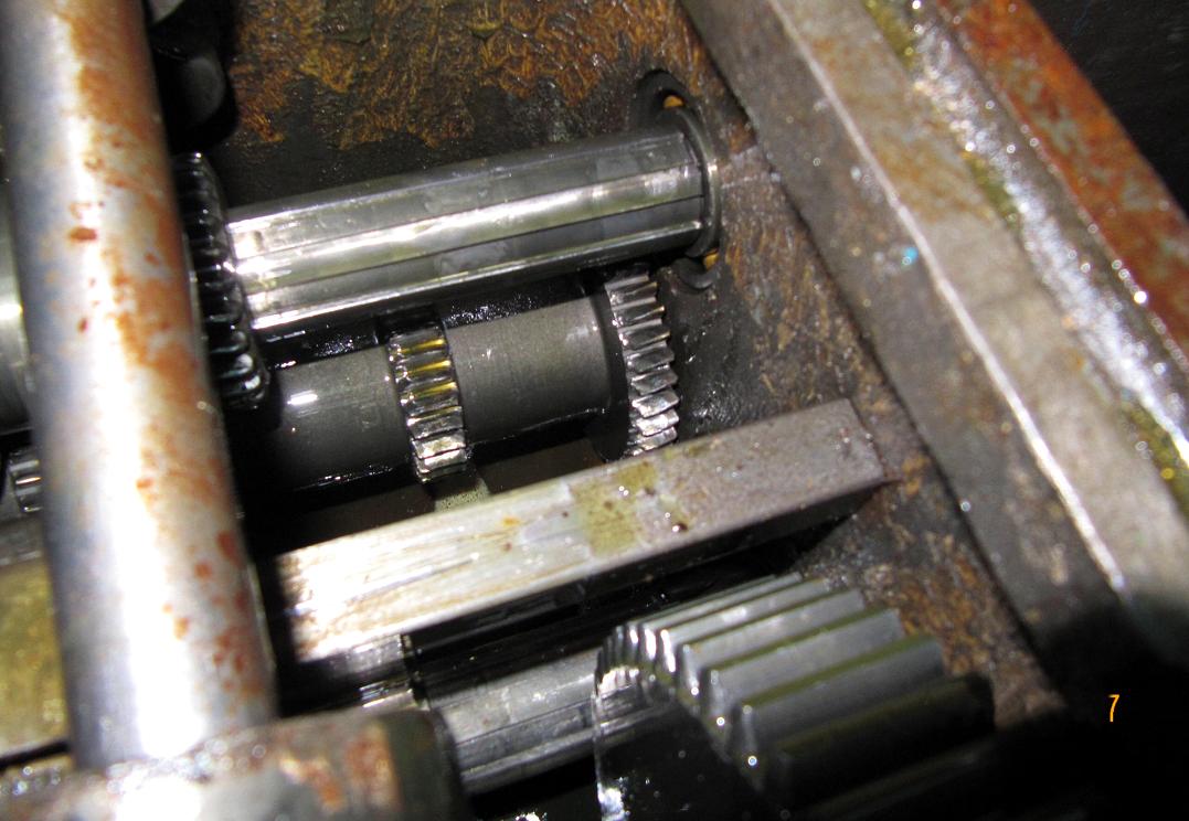
Knowing that the lathe was intended for professional rather than training use, the makers included markings to assist in the cutting of threads with 2, 3, 4 and 5 starts. The marks were inscribed on an annular plate, attached to the gear on the end of the headstock spindle, and showed the tooth spacing to be used for the first thread of 4, 6 and 8 starts. To obtain a 2-start thread the second thread was cut when the index tooth came opposite the first-start position whilst for 3-start threads alterative divisions marked for 6 starts could be used. The gear immediately below - on the second-motion shaft - was engraved with an arrow by which means the operator could cut the first thread with the arrow against the appropriate mark and then, for subsequent starts, withdraw the graduated gear, turn the spindle until the mark for the next start came opposite the index tooth, then re-engage the gear on the spindle.
Continued below:
|
|
|
|
|
|
|
 |
|
|
|
|
|
|
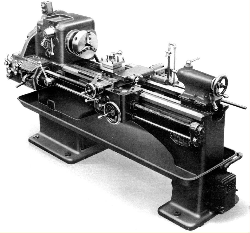
Early Mk. 1 recognisable by the headstock-mounted clutch lever (to the left of the concentrically-mounted pair). This model is equipped for drive by flat belt from a ceiling-mounted countershaft or line-drive system, a V-shaped belt guard being fitted around the input pulley
|
|
|
|
|
|
|
|
|
|
|
|
|
|
 |
|
|
|
|
|
|
|
|
|
Continued:
Carriage assembly:
Power sliding and surfacing feeds were driven by a separate feed shaft from the screwcutting gearbox and both selected and engaged by a simple push/pull button - an arrangement inferior to that on most Harrison lathes where feed engagement was provided by a separate lever with an absolutely positive snap in-and-out action. The power-feed take-off was passed though a safety clutch that slipped automatically a pre-set loading. Lubrication of the apron was manually, through a filler hole - the oil being fed into a distribution tray from where it was carried by wicks to the various parts of the mechanism.
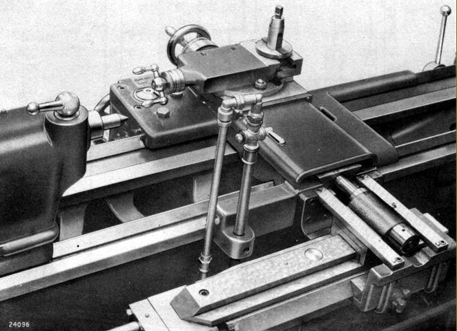
Cross and top slides were entirely conventional with the former having a full-circle handwheel and the top slide a traditional two-finger grip that allowed very precise manipulation of the feed on delicate jobs. The micrometer dials zeroed, with that on the cross slide being of a remarkably large diameter for its era and with particularly clear engravings. As a taper-turning unit was an accessory (and required room to mount) the cross slide was of the "short" variety with two inherent disadvantages: less support for the top slide and a concentration of wear in the central part of its ways. However, Edgwick did provide one unusual and very handy fitting, a device that secured the top slide exactly parallel to the bed ways. Positioned to the left-hand front side of the slide the unit consisted of a hardened plunger that passed though accurate bushings is the base of the top slide and the cross slide. A swivelling latch was used to hold the plunger out of engagement but when, for boring or other parallel work, it was necessary to have the tool in alignment with the headstock spindle, the latch could be swung out and the plunger pressed down.
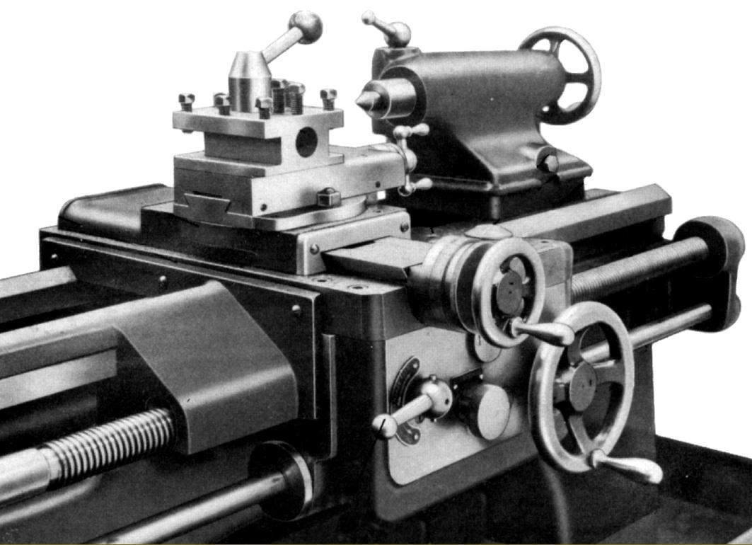
Although various optional toolposts were offered, including 4-way and American types, the standard fitting was a well-made and robust square turret with three sides milled to take rectangular-sided tools and the fourth bored 1.25" to accept round fittings such as boring tools and reamer and drill holders. A hardened plunger, running through hardened bushes, located the post, the whole unit being spring mounted so that, upon slackening the locking handle, the block was lifted and could be rotated to a new position.
Of substantial construction, the tailstock carried a No. 3 Morse taper barrel - when a No. 2 might have been expected on a machine of this size and era - and could be set over for the turning of shallow tapers. An attached lever, operating a simple cam-form cross bar that pulled on an eye-bolt, locked the tailstock to the bed - no self-hiding loose spanners to waste the time of the Edgwick operator.
Supplied as part of the lathe's standard equipment was a 4-way toolpost, one 7-inch driver plate, one 12-inch faceplate, two No. 4 Morse taper centres (one hard, the other soft), a grease gun and the necessary Whitworth spanners..
|
|
|
|
|
|
|
|
 |
|
|
|
|
|
|
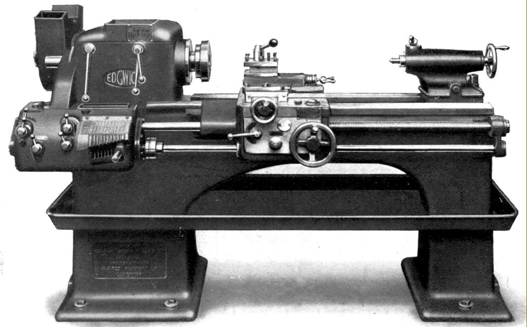
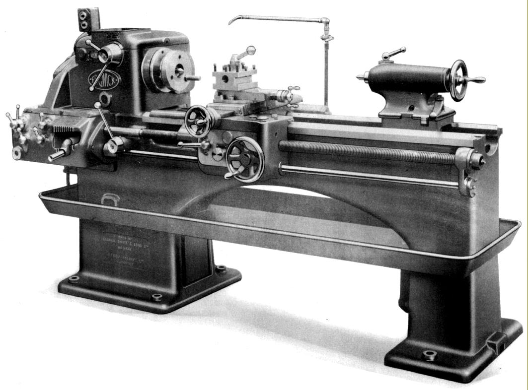
Later model with spindle clutch operated by a lever to the right of the screwcutting gearbox. The arched bed followed design practice contemporary to the 1930s
|
|
|
|
|
|
|
|
|
|
|
|
|
|
 |
|
|
|
|
|
|
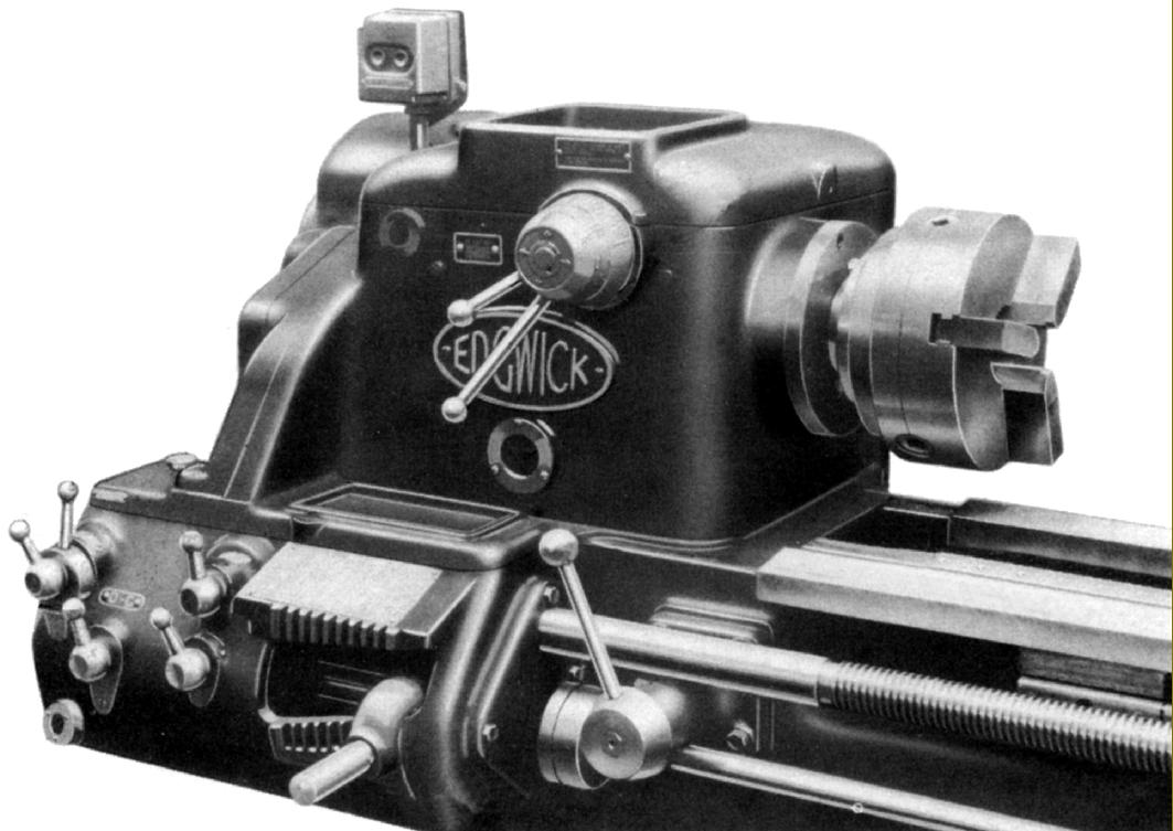
The micrometer dials zeroed, with that on the cross slide being of a remarkably large diameter for its era and with particularly clear engravings
|
|
|
|
|
|
|
|
 |
|
|
|
|
|
|
|
|
|
|
|
|
|
|
|
|
|
 |
|
|
|
|
|
|
Markings to aid the cutting of multi-start threads
|
|
|
|
|
|
|
|
 |
|
|
|
|
|
|
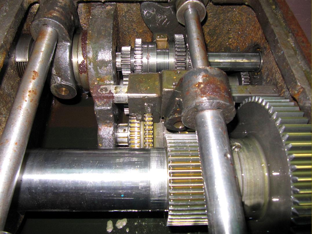
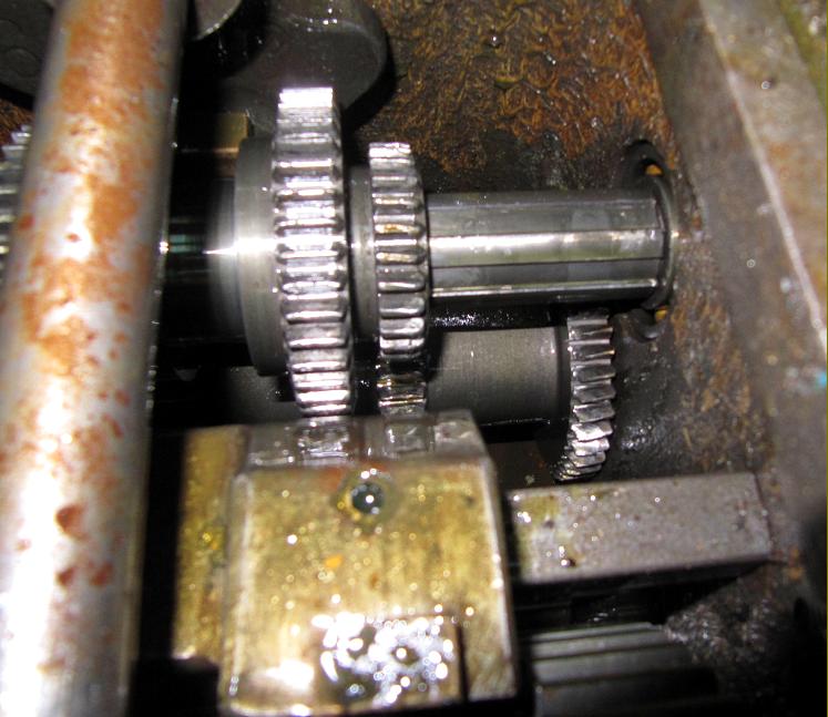
Inside the geared headstock
|
|
|
|
|
|
|
|
 |
|
|
|
|
 |
|
|
|
|
|
|
|
|
|
|
|
|
|