|
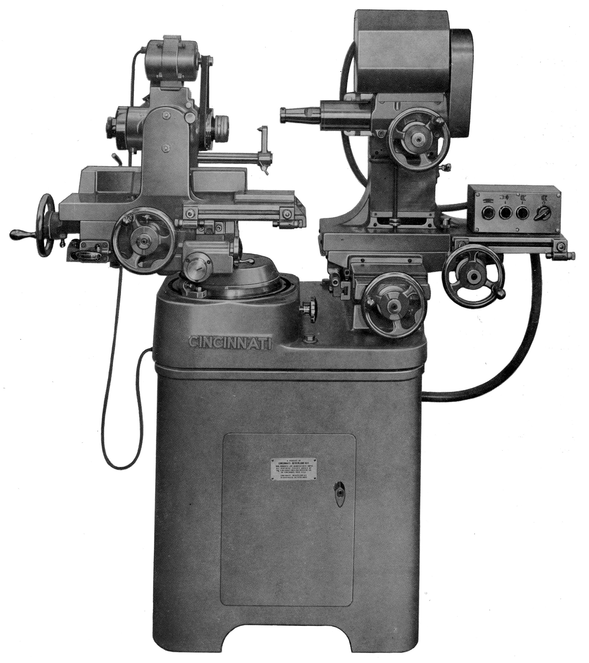
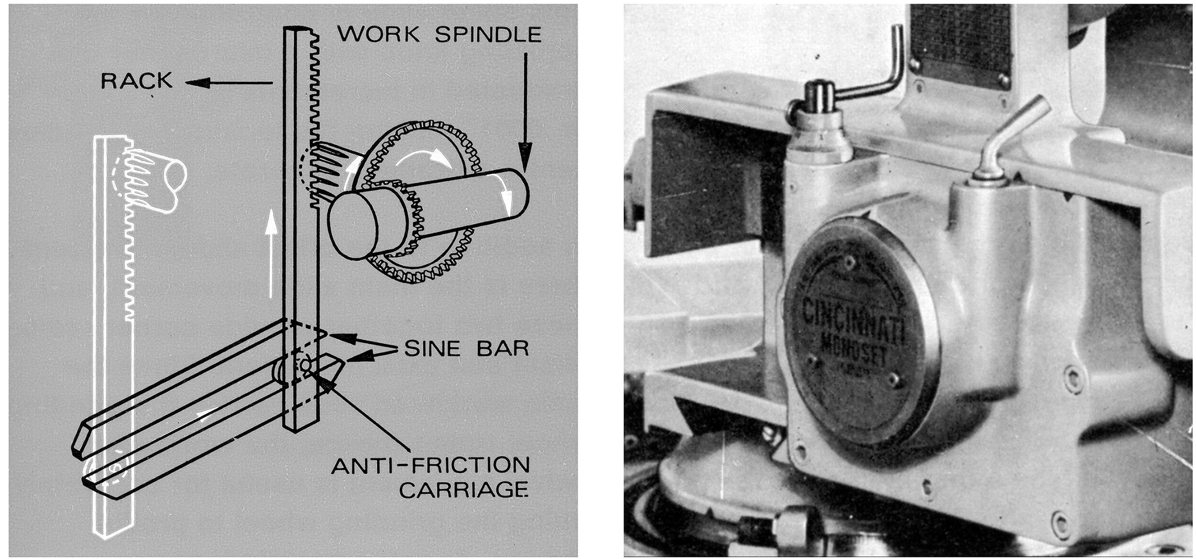
Manufactured by Cincinnati from the 1940s into the 1980s, the complex and versatile "Monoset" tool & cutter grinder was a very much more sophisticated machine than the company's earlier and long-lived No.2 model. Still very popular, companies can be found online that recondition and offer the Monset with DRO systems and other upgrades, modifications and accessories.
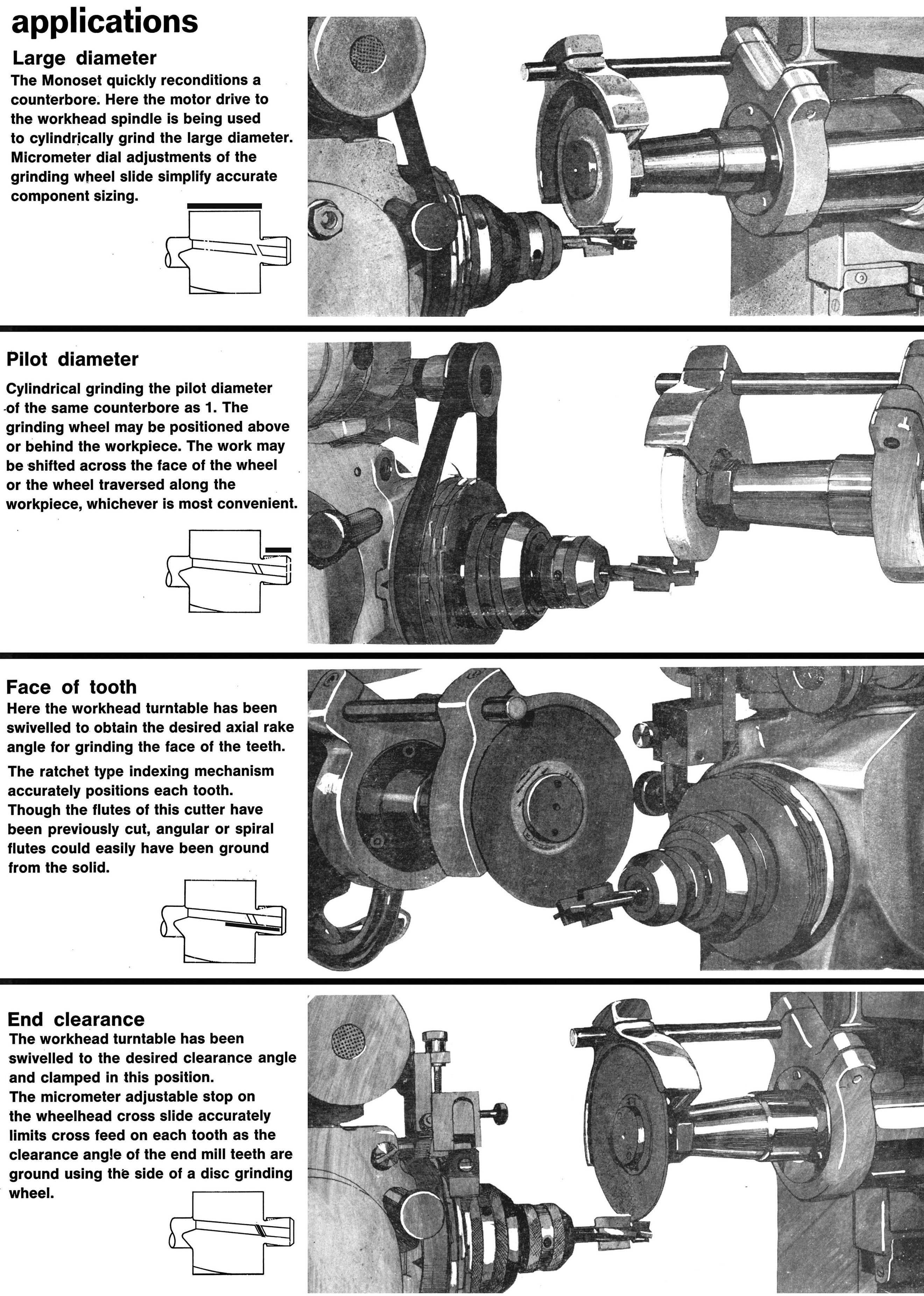
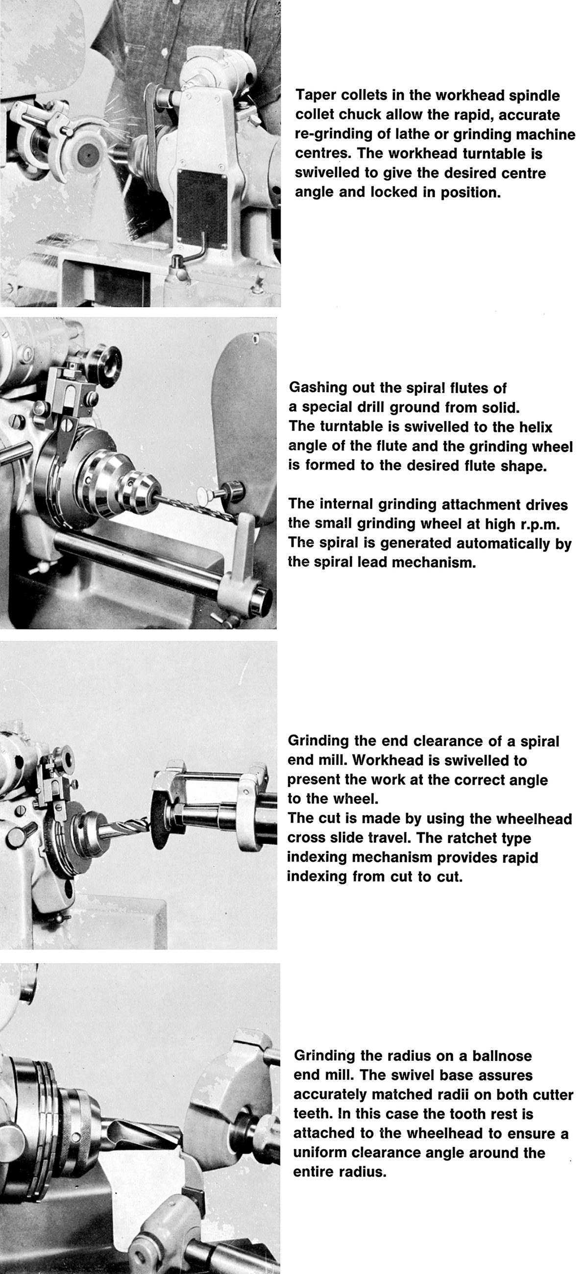
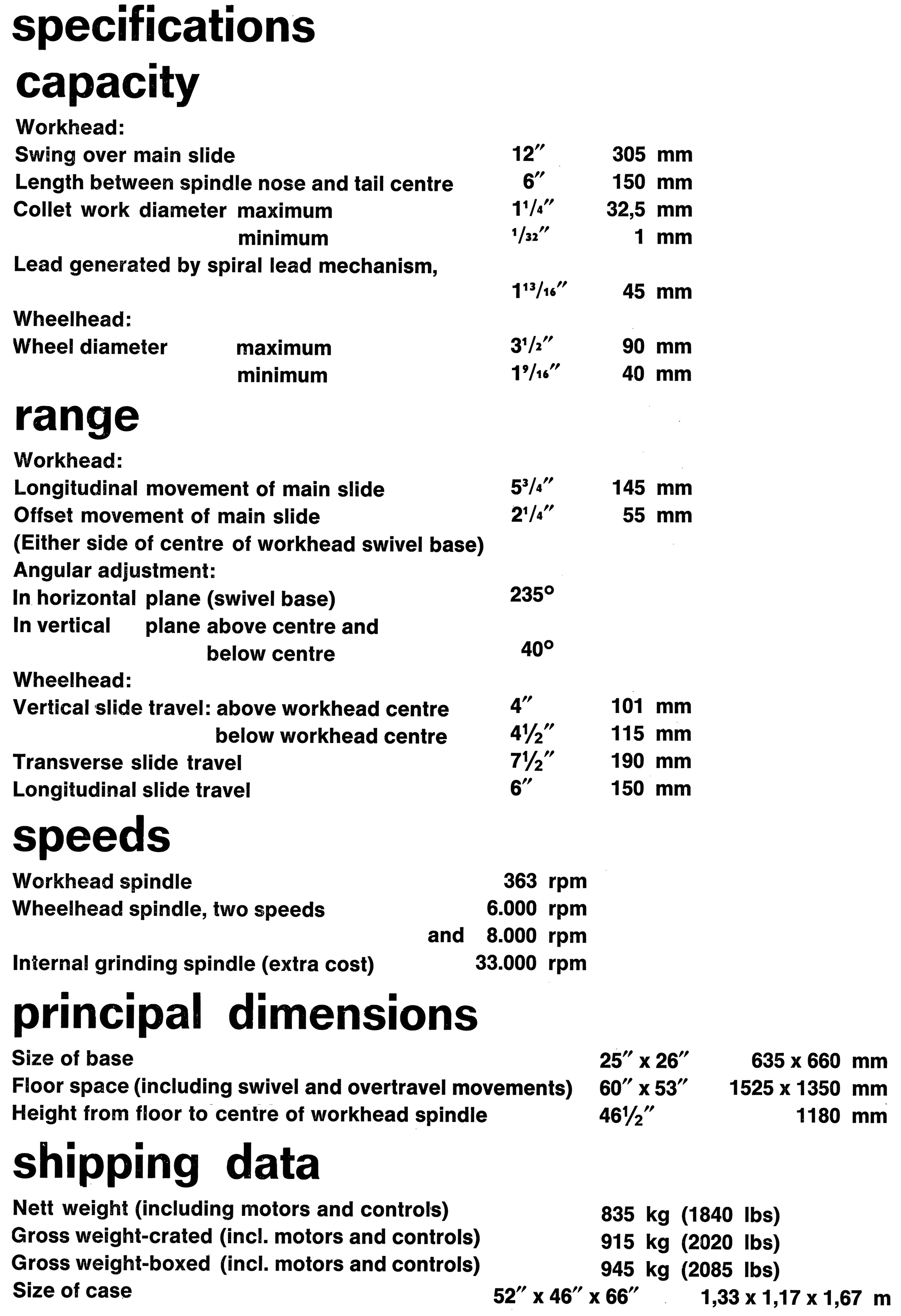
As its name implies, this heavily-built 2020 lb machine was designed to perform as many operations as possible at one setting and could grind and recondition a wide variety of milling cutters. It could also turn a solid bar into an intricate milling cutter, a ball-point tracer finger or a spiral end mill, grind concave and convex radii and automatically generate straight or tapered, right or left-hand infinitely variable spirals with a single and simple adjustment.
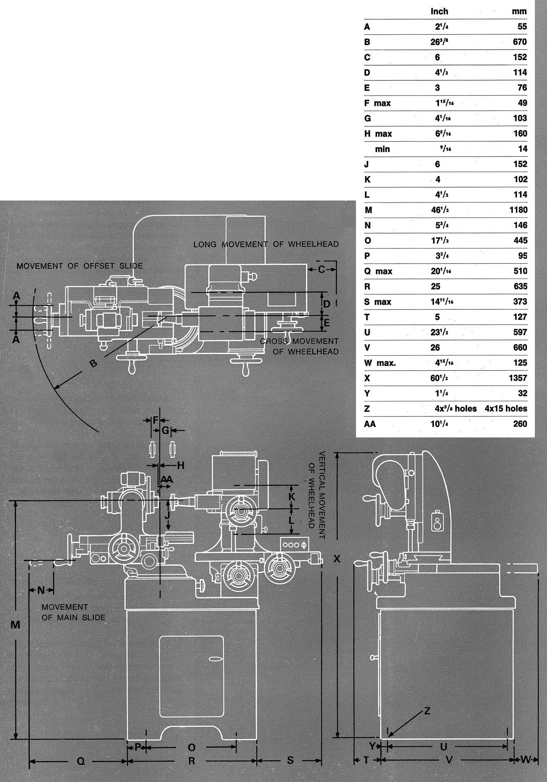
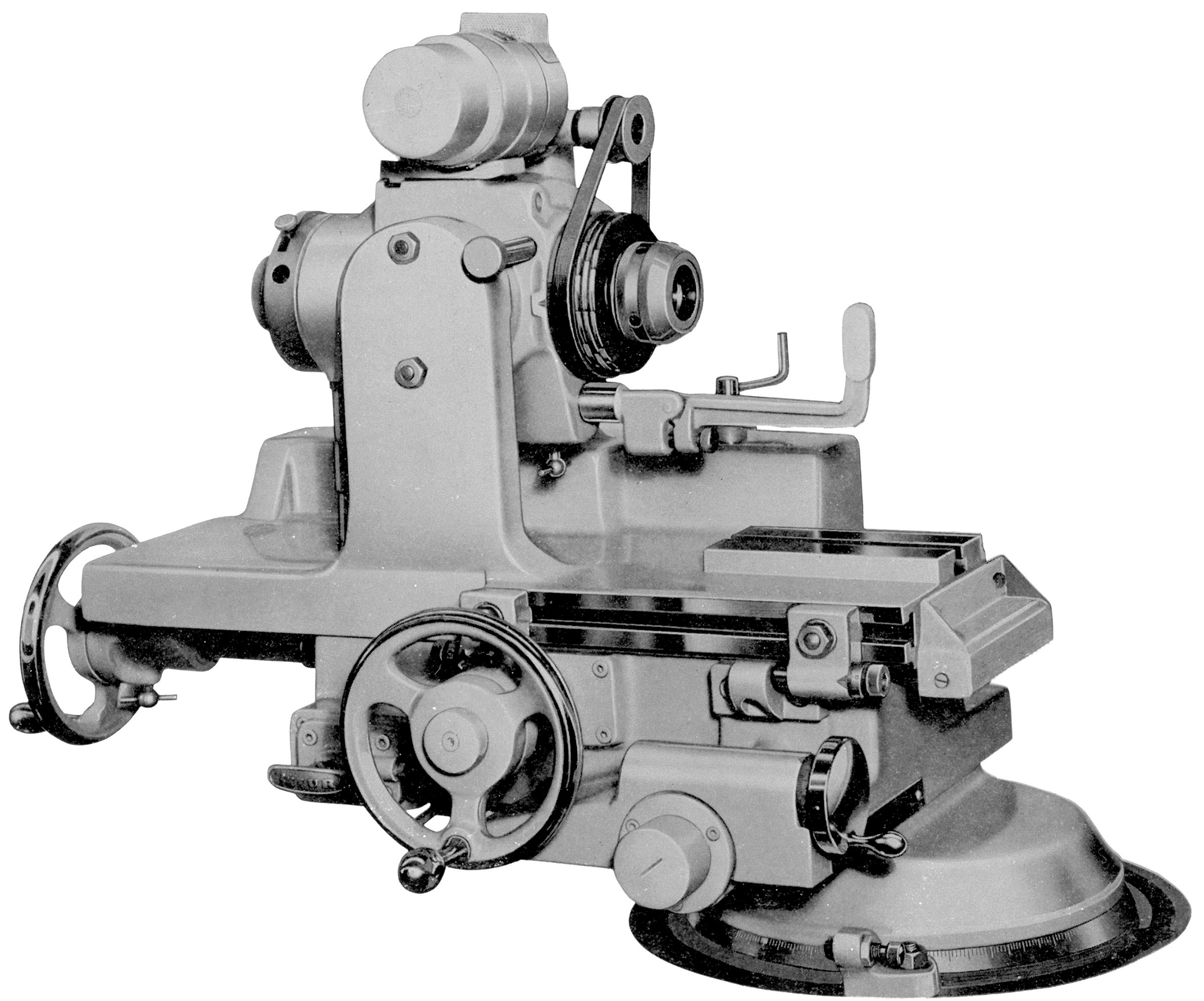
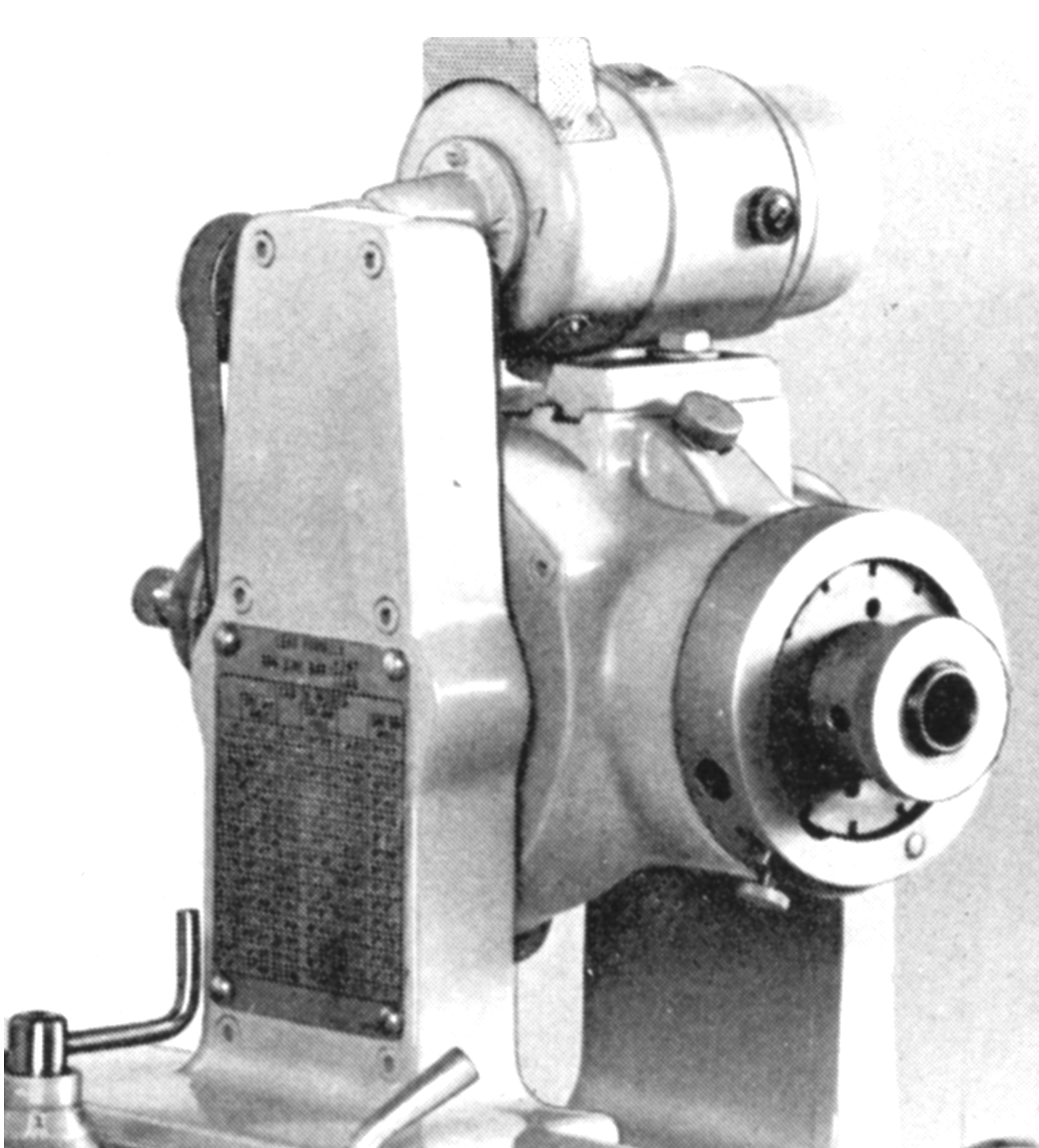
Five separate axes of travel were available that could be used singly or in combination. The massive workhead unit was mounted on a smooth-turning turntable base and able to be tilted vertically, swivelled horizontally through 235°, moved on a longitudinal slideway. Its centreline was able to be displaced horizontally for the accurate grinding of cutters and cylindrical shapes requiring the formation of convex or concave radii. The swivel base was equipped with adjustable stop dogs and a clamp that did not disturb the chosen setting.
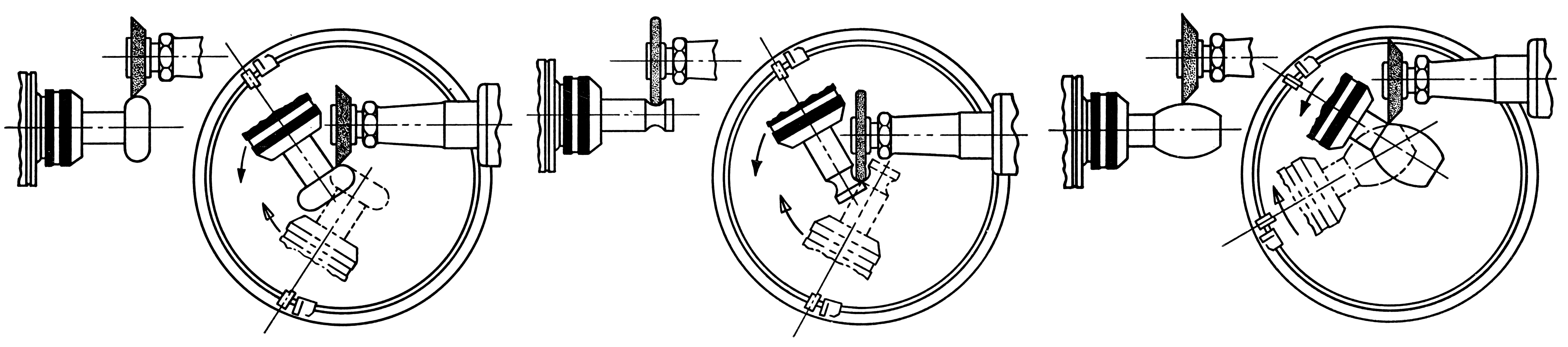
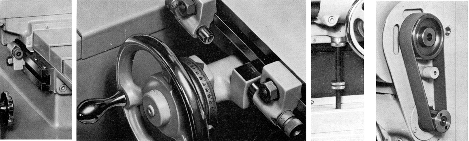
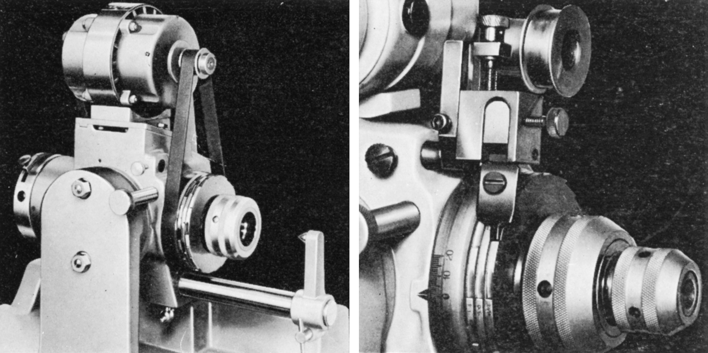
Mounted independently from the workhead, the grinding head took wheels up to 90 mm in diameter and had, by the use of a double-step pulley, two speeds of 6000 and 8000 r.p.m. At extra cost, an internal grinding attachment could be provided that ran at 33,000 r.p.m. The head could be adjusted longitudinally, in traverse and vertically with all slides having very large micrometer dials and travel stops--these being held T-slots and with fine-thread adjustment screws. The longitudinal slide had two opposed stops, the cross slide a single dog - that allowed a rapid and accurate return to the grinding position having backed the wheel away from the work - and the vertical a single micrometer-equipped stop that allowed the wheel to be returned accurately to the grinding position after a vertical retraction. To simplify the settings need to grind cutter clearance angles, scales were proved on both the vertical and traverse slides that showed the correct position of the grinding wheel for obtaining the correct clearance angles when grinding above or below the work. The scales were graduated from 0 to 25° in both directions and the vertical slide pointer adjustable vertically so that it could be used when grinding below the normal central position.
By using a simple but ingenious built-in spiral lead mechanism, the makers claimed that even a beginner at tool and cutter grinding could use a Monoset to produce, direct from bar stock, accurate helical cutters. The mechanism consisted of an adjustable sine bar, linked to the workhead spindle by rack and pinion gearing and a bevel-gear drive. An anti-friction 'carriage' rested in the lower end of the rack and travelled between a pair of hardened steel strips that replicated a sine bar. The main slide carried the rack with the sine bar mounted in the offset slide. With the mechanism is engaged, movement of the workhead slide caused the workhead spindle to rotate - and so generate a helical lead. By using a hand-crank, the angle of the sine bar could be changed and so infinitely-variable helical leads obtained. A table of common leads with corresponding sine bar settings was located directly above the adjusting crank, allowing the operator to see, at a glance, the correct sine bar angle. A micrometer dial on the adjusting crank was graduated in two-minute increments - this enabled the operator to set the sine bar angle quickly - and with great accuracy. For work that did not involve the spiral lead mechanism, simply dis-engaging a single clamping lever freed the spindle for cylindrical grinding or straight indexing.
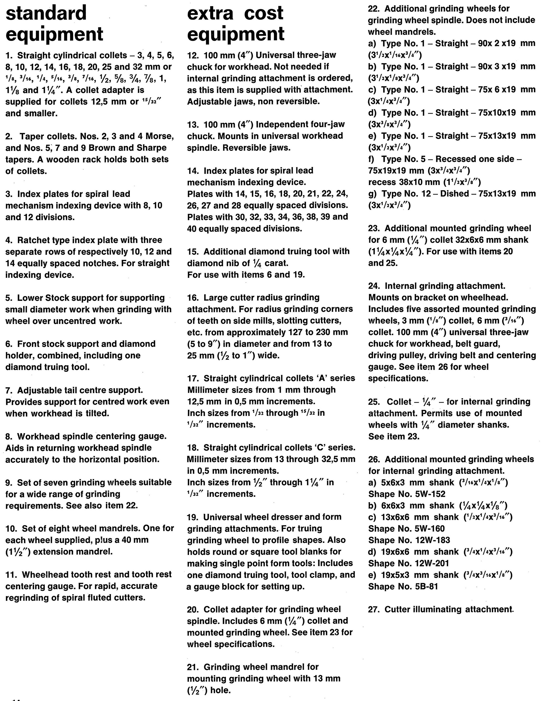
For indexing with the spiral lead mechanism, an indexing device on the rear end of the workhead spindle accurately positioned the spindle with the spiral lead mechanism. Three index plates with 8, 10 and 12 divisions were supplied and allowed for virtually any number of indexes up to 40. The 12 notch plate was also provided with four extra notches to permit the indexing of 8-tooth cutters. A ring-shaped cover protected the indexing notches and incorporated an indexing panel.
Indexing could also be carried out without the spiral lead mechanism, the arrangement consisting of three plates with 10, 12 and 14 divisions and a spring-loaded, adjustable index finger mounted on the spindle housing that allowed instant selection of the desired index; the operator simply had to release a single clamping screw to shift the index finger from one plate to another.
For many simple tool and cutter grinding jobs a Monoset might be considered overkill and a simpler machine would indeed cover most requirements of an ordinary shop. But, if you want to enjoy the pride of ownership and the versatility of one of the best of all conventional T & C grinders, the Monsoet is very hard to beat (though you will need the operator's manual…)
|
|