|
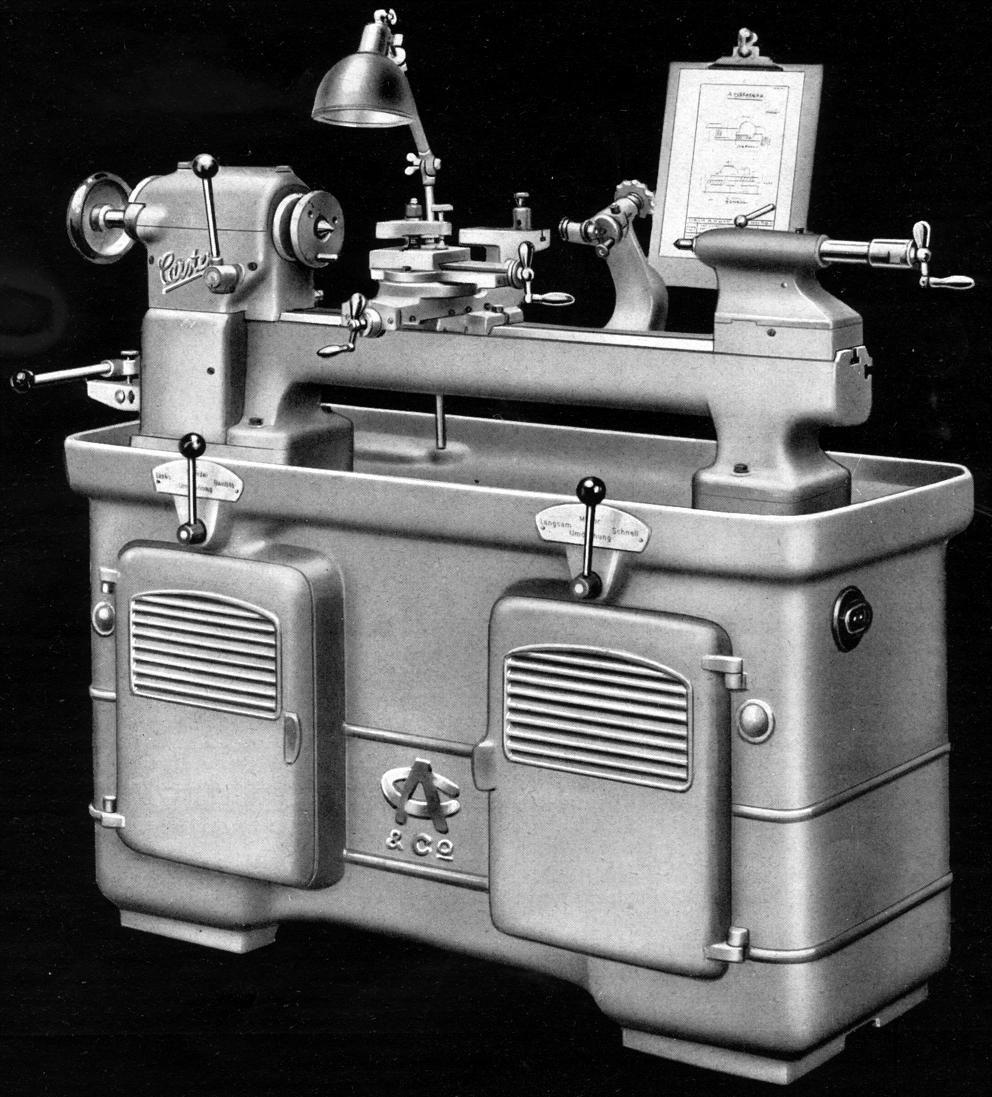
Typical of the sort of lathe offered by Carstens, the "D" Series (DLZP, DLZK, DLK, DZK and DMR) were very high quality machines (directly developed from the earlier D lathes of the 1920s) that sold in a profitable segment of the market. In the UK Swisten branding was used, with various models advertised simply as "Foreign" and sometimes with a plate on the machine itself reading: The "Swisten" Foreign). Although early lathes (see below) were offered for bench mounting - various stands were also listed that, besides the usual type of the era with cast-iron legs and wooden tool trays, also included some unusual examples made from angle iron with the faces sheeted in wire mesh. Early examples of the latter had the countershaft mounted externally, low at the back but (probably by the mid 1920s) this had been reposition rather more neatly to the inside. On the iron stands the top of the legs (or the chip tray, if used) were hand scraped dead flat where contact was made with the bed feet. Later models were supplied on either a particularly heavy cast-iron cabinet, formed in one piece for maximum rigidity and strength (and intended for use on the shop floor) or on a lighter yet still strong stand rather like the earlier pattern (but improved in detail) and ideal for use in a toolroom. Mounted inside the heavier stand was a 2½ hp two-speed 3-phase motor capable of running at 700 or 1400 rpm and controlled by two easy-to-use vertical levers, pivoting on the front face, one for high and low speeds the other for start, stop and reverse. A six-step, V-belt drive provided, in conjunction with the 1 : 3.5 backgear system, a total of 18 speeds from a usefully low minimum of 25 rpm to a disappointingly slow maximum of 1400 rpm. Most makers of this class of machine offered alternative speed ranges to suit their customers' special requirements and Swisten were no different: not only listing a range from 50 to 2000 rpm (much more likely, one would have through, to suit the type of work this sort of lathe would be called upon to perform) but also the option of a more expensive countershaft that carried a clutch and brake unit able to control the spindle without stopping and starting the motor.
Completely enclosed, the headstock held a 29/22" (23 mm) bore hardened (nitrided) spindle spinning in precision plain bearings designed for at least 20,000 hours of running before adjustment was necessary.. The spindle nose was threaded, carried a No. 3 Morse taper and could be fitted with draw-in collets with a maximum through capacity of 5/8" (16 mm). Backgear was arranged by the usual Carstens system of planetary gearing built into the largest diameter of the spindle's flat-belt pulley and operated by a single lever protruding from the front face of the headstock.
Screwcutting on the DLZK and DLK was arranged through a set of 23 changewheels with the 6 t.p.i (or 5 mm pitch) leadscrew running down the centre line of bed, beneath the ways, where it was completely shielded from swarf and dirt. Its position meant that it was the minimum distance away from the cutting tool, almost directly beneath it and hence ideally placed to provide the most rigid form of drive.
On the DZK and DLZK models power sliding and surfacing was fitted, driven from a separate power shaft that passed along the front face of the bed and with the drive arranged in such a way that the operator was able to switch between screwcutting and feeds by the movement of a single lever. 6 rates of feed were available, selected by a horizontal lever protruding from a slot at the left-hand end of the bed. The sliding rate varied, per revolution of the spindle, from 0.05 to 0.21 mm (0.002" to 0.0084") and the cross feed at exactly half that from 0.025 to 0.105 mm (0.001" to 0.42"). It was also possible to specify, at extra cost, feed rates that were twice as fine (i.e. in the case of the longitudinal feed from 0.001" to 0.0042"). Longitudinal feed was provided with a micro-adjustable, mechanical knock-off stop and the same system could be arranged, at extra cost, for the cross feed. Although the technical literature does not make it absolutely clear, by a process of deduction it would appear that the DLZK had both a leadscrew and a power-feed shaft, the DLK just a leadscrew and the DZK a power-shaft, but no leadscrew.
Claimed by the makers to be of a: "particularly powerful design and, even under the heaviest of cuts, glides smoothly along the bed." the carriage assembly was indeed very heavily built. Although a bold claim, it was undoubtedly true, the writer's experience of these machines being that the makers went to inordinate lengths to get the feel of the whole machine "just right". Strict quality controls were in place to ensure that only the finest materials were used, machining was carried out to the highest standards and the final build could involve several trial assemblies and strip-downs before the nod of satisfaction was given by the dour foreman in charge of the department.
Of the full-length type, the cross slide was machined flat on its top surface - where it could be used to mount a rear toolpost or other fittings. The 10 t.p.i (or 3 mm) pitch cross-feed screw was of large diameter and ran though a long bronze nut although unfortunately this was not, as on some competing makes, adjustable to take out backlash. The top slide swivelled through 360º and was graduated with degree marks for its full circumference. The lathe occupied a floor space of 600 mm by 1750 mm (24" x 70" and weighed approximately 765 kg 91685 lbs).
Carstens offered not only the usual range of accessories - chucks, collets, steadies, taper-turning attachments and toolposts of various kinds - but also a beautifully engineered powered milling attachment that mounted onto a vertical slide. It was equipped with a 1340 rpm 0.18 kW 220 /380 V motor and employed a spindle able to accept boring tools up to 13 mm in diameter. The head was able to be swivelled through 360°, could be fitted on either side of the main casting and, because it was intended for relatively heavy-duty work, was driven at slow speeds though worm-and-wheel gearing. As a further refinement, for the cutting of splines and similar indexing work, a small plunger unit was provided that bolted to the changewheel bracket and allowed an ordinary gear to be used for the necessary dividing and spindle locking.
It is likely that the maker would also have offered an alternative, direct-drive high-speed head able to accept small end mills, slot drills and grinding stones secured by a draw-in collet arrangement.
If you have a Carstens or Swisten-branded lathe (or any publicity material) the writer would be pleased to hear from you. This section on DRLZP, DMR, DLZK, DZK and DMR lathes continued here
|
|