 |
|
|
|
|
|
|
|
|
|
|
|
|
|
|
|
|
|
|
|
|
|
|
|
|
|
|
|
|
|
|
|
|
|
|
|
|
|
|
|
|
|
|
|
|
|
|
|
|
|
|
|
|
|
|
|
|
|
|
|
|
|
|
|
|
|
|
|
|
|
|
|
|
|
Illustrated below - and supplied by Buck & Ryan of London, probably in the early 1920s - is a developed version of the Model DLRN, a machine that was to become the much improved and rather heavier "DLZK, DLK and DZK" Series. The example shown, although in 'well-used' condition when found, has been sympathetically resorted and is now driven by a 3-phase motor and inverter giving variable speed drive through the original smooth-running flat belt drive system. A comparison with the later models shows the latter to have been clearly based on the design of the earlier but with heavier, more rigidly designed castings with only the form of the bed surviving unchanged.
Several features of the Carstens were also to be found on contemporary Boley lathes, where a real attempt was made to give rigidity to the cutting tool and the method of moving it: the bed was heavily-built and especially wide with a single V-way at the front and a flat at the back to guide the carriage - but with the headstock and tailstock using a flat-topped, common centre section with bevelled edges and a central T-slot for clamping. In the form of open-topped box, the apron was bolted to both the front and back of the saddle - thus forming a rigid, enclosed structure to support the leadscrew clasp nuts (themselves contained within a heavy, bolt-on housing). As a consequence of these various features, the headstock sat well within the edges of the bed with the carriage riding upon them - so allowing the forces generated by the cutting tool to be taken away on a path that enjoyed an advantage in leverage when compared with less well-built machines. However, despite all these efforts to encourage stiffness, the headstock was bolted to the bed by just two clamps (engaged in the central T slot) with each tightened by an eccentric shaft with a hole for a Tommy bar where it emerged from the rear face of the casting. Probably imported to the UK (and possibly other markets) with just a 3.5-inch centre height, the writer's guess is that the distributors fitted a set of with well-made, 2-inch riser blocks under headstock, tailstock and top slide - the first two with quick-release fixings that enabling them to be slid-off their fastenings easily.
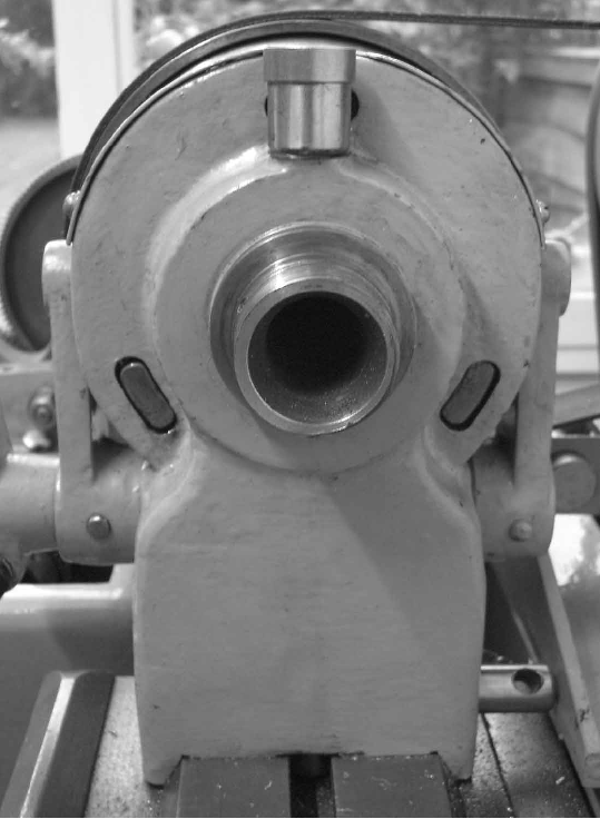
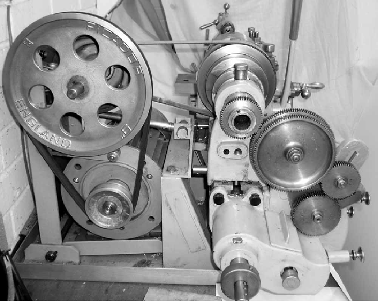
Typical for the era, the headstock had an "open" face that, whilst it exposed the full depth of the 3-step flat-belt pulley and made speed changes easy, meant the bearings had less lateral bracing than on later versions. The spindle was bored through 1.5-inches, carried a 10 t.p.i nose thread and ran in very substantial, adjustable plain bronze tapered on their inside surfaces and with a ball-bearing thrust race at the rear. Backgear was the "trade-mark" type for the maker with a 3.5:1 epicyclic speed-reducer built into the largest diameter of the spindle's flat-belt drive pulley; this mechanism consisted of an internal ring gear and three Tufnol planet gears engaged by a leaver protruding through the front face of the headstock.
Although later Carstens lathes all seem to have been advertised with screwcutting by changewheels, the earlier model was supplied with a pair of threading and feeds gearboxes that combined to give an astonishing range of 140 pitches - and feeds from 0.075 mm to 3.4 mm per revolution of the spindle. Because the leadscrew ran underneath the bed, along its centre line, the designers were face with the problem of transmitting a drive through a gearbox then out again and sideways. They took advantage of this dilemma by employing two boxes: the first (mounted on the front of the bed) contained a conventional "tumbler" arrangement under the control of a lever engaged in a serious of 7 holes together with a 3-position lever to select left and right-hand travel of the carriage; the second, bolted to the bed's end face, took the drive "sideways" and was controlled by a selector that slid into and out of the end together with a two-position lever on the front. The position of the 5 mm pitch, 22 mm-diameter leadscrew meant that not only was it completely shielded from swarf and dirt but also the minimum distance away from the cutting tool, almost directly beneath it and hence ideally placed to provide the most flex-free form of drive. The bronze clasp nuts (supported in the middle of a cast-iron box section as previously explained) were especially large and engaged by a Boley-like lever beneath the apron working through a rack-and-pinion arrangement and with an over-centre type lock. The drive could be instantly disengaged either by an automatic mechanism, tripped by a block locked into a slot that ran down the front face of the bed, or manually by a button on the front face of the apron.
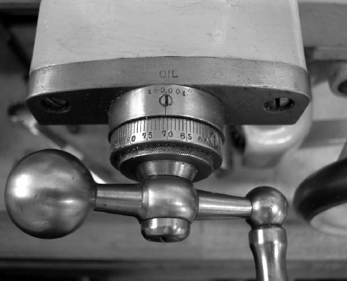
Carrying adjustable micrometer dials of, for the time, very reasonable diameter and clarity, the compound slide was rest was superbly constructed. However, on the machine shown immediately below, while the dials had been hand stamped with fractional inch graduations - underneath was a second set of properly engraved metric markings - obviously a case of the importer pulling a fast-one on his customers and hoping that they would never notice. Experiments with the machine showed that when the top slide revolved ten times the tool post moved only 0.978" (instead of the indicated 1.00") so giving a discrepancy that at least was on the "safe" side.
Of the full-length type, the cross slide had its rear section increased in thickness and the top surface machined for the mounting of a rear toolpost and other fittings. The long-travel top slide with its exposed slideways bore a strong resemblance to those used generally on precision plain-turning lathes - as did its large mounting boss, a design also seen on smaller Carstens and Swisten lathes. This latter fitting, necessary to get the toolpost up to height, combined with a very deep tailstock sole plate, probably indicate that the lathe was originally designed to have a rather lower centre height.
Looking just as though it had been lifted from one of the maker's precision plain-turning lathes (which in all probability it had) the tailstock was typical of the type in having a barrel that was always fully supported within the casting no matter what its position. Its sole plate was enormously thick and of the kind once described as: "built up in the sand" - a reference to the likelihood that its manufacture had been quickly and crudely altered at the casting rather than pattern-making stage. Unfortunately the barrel locking arrangement was the type that relied upon a slot in the casting being closed down by a screw - a system that normally leads to breakages when the unit becomes worn. However, on the Swisten, this arrangement was properly engineered with both longitudinal and vertical slots being used to isolate a small section of casting that could be clamped with greater pressure than would otherwise have been possible..
|
|
|
|
|
|
|
|
|
|
|
|
|
|
 |
|
|
|
|
|
|
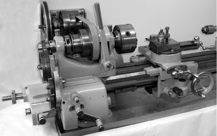
An early example of what became the Carstens (Swisten) "DLZK, DLK and DZK" Series supplied by Buck & Ryan of London, probably in the late 1920s or early 1930s
|
|
|
|
|
|
|
 |
|
|
|
|
|
|
|
|
|
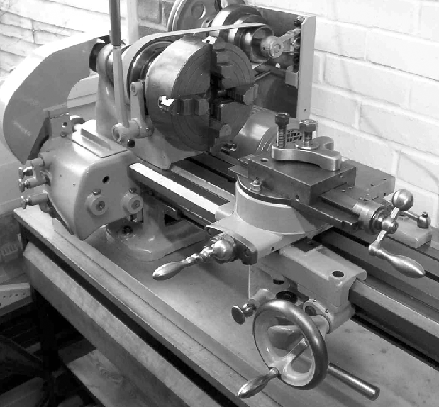
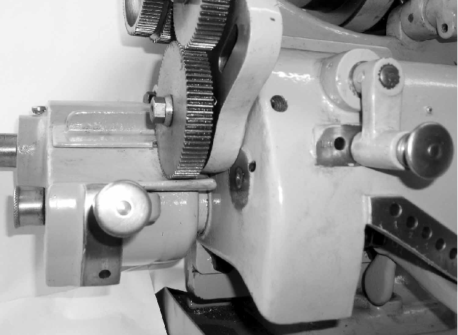
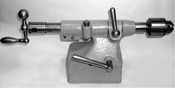
The distinctly European lines of the Carstens (Swisten) 5-inch. The button on the apron provided an "instant" method of releasing the carriage drive
|
|
|
|
|
|
|
|
|
 |
|
|
|
|
|
|
|
|
|
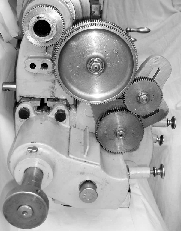
The DLRN was modified to include an unusual combinations of two screwcutting gearboxes - here, with the covers removed,
|
|
|
|
|
|
|
|
|
 |
|
|
|
|
|
|
|
|
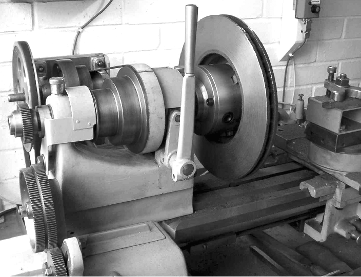
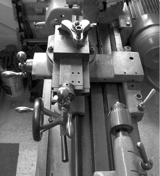
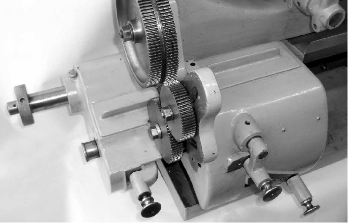
Old lathe, modern job. Turning a brake disc from a Ford Mondeo. The large lever on the face of the headstock operates the patented Carstens epicyclic backgear assembly built into the largest diameter of the headstock pulley
|
|
|
|
|
|
|
|
|
 |
|
|
|
|
|
|
|
|
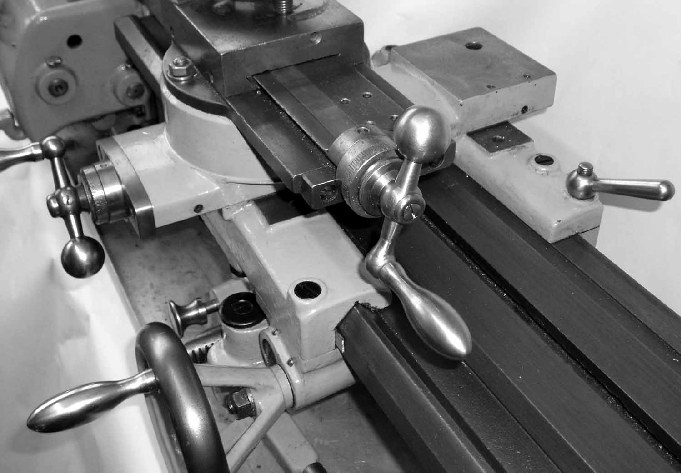
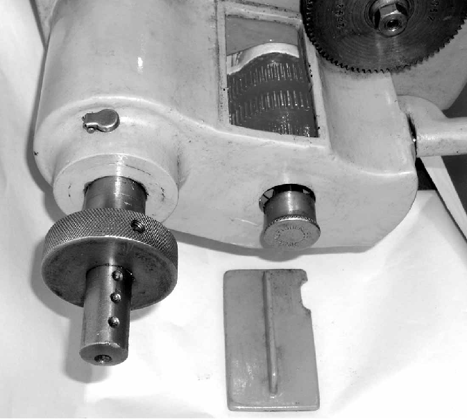
The long-travel top slide with its exposed slideways bore a strong resemblance to those used generally on precision plain-turning lathes. The slide's tall mounting boss was a design feature also seen on smaller Swisten lathes and, combined with a very deep tailstock sole plate, probably indicate a lathe originally designed to have a rather lower centre height. Note the neat, built-in thread-dial indicator on apron's front face
|
|
|
|
|
|
|
|
|
|
|
|
|
|
 |
|
|
|
|
|
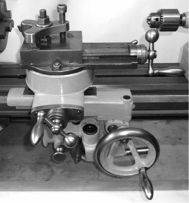
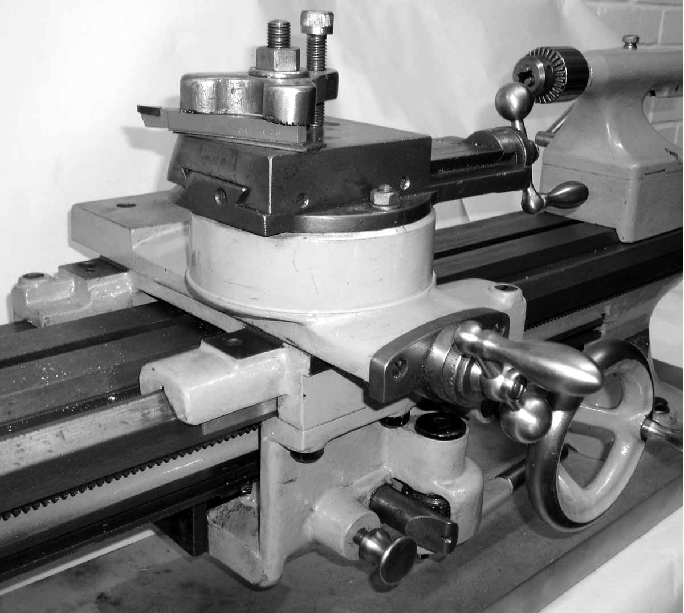
A successful design introduced in the early 1920s and used for several decades, the apron was reduced to its elements of simplicity and carried no unnecessary metal. To engage the leadscrew clasp nuts a rack-and-pinion drive was used, operated by a lever that can be seen pointing towards the tailstock end of the bed. The apron was a "double type" - passing under the bed and being bolted to both the front and back of the saddle
|
|
|
|
|
|
|
 |
|
|
|
|
|
|
|
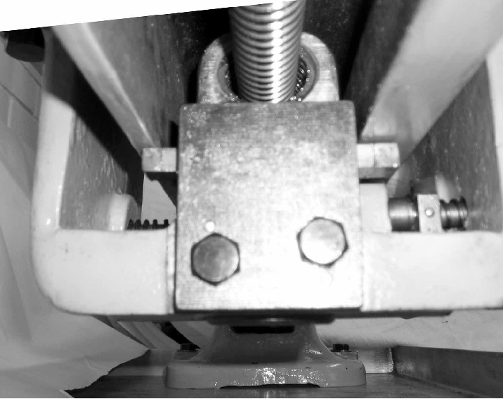
Above and below: the cross slide was of the full-length type with its rear section increased in thickness and the top surface machined for the mounting of a rear toolpost and other fittings.
|
|
|
|
|
|
|
|
|
 |
|
|
|
|
 |
|
|
|
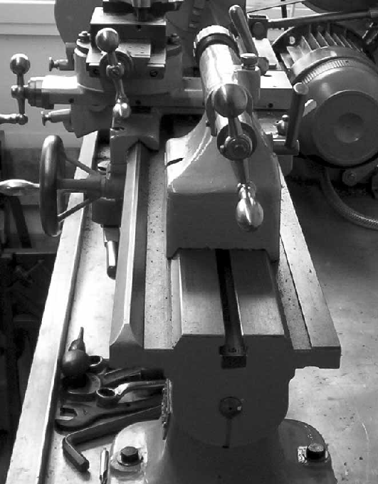
A view clearly showing the enormous height of the post carrying the top slide
|
|
|
|
|
|
|
|
|
|
|
|
 |
|
|
|
|
|
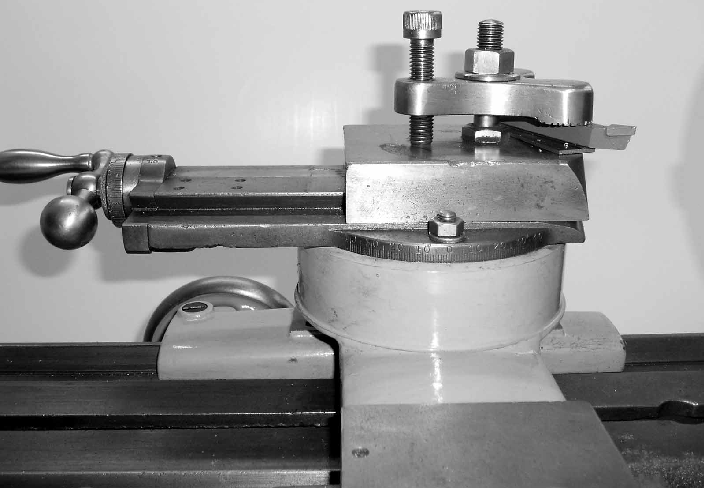
The hand-stamped micrometer dial hid another beneath with the correct (engraved) metric graduations
|
|
|
|
|
|
|
 |
|
|
|
|
|
|
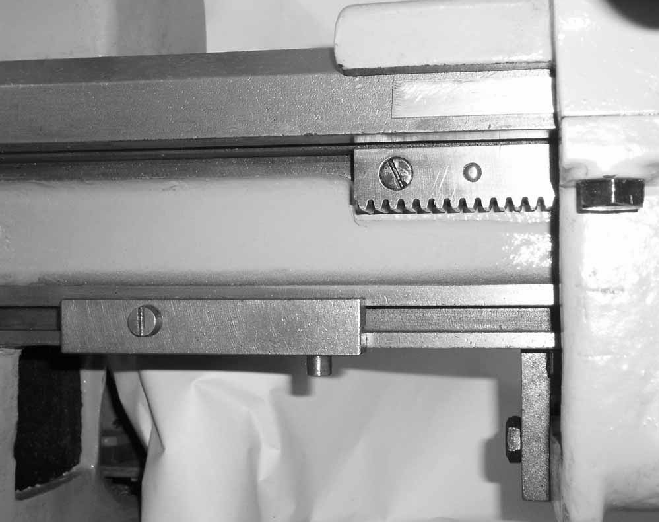
The bed was especially wide and heavily-built with a single V way at the front and a flat at the back to guide the carriage. The tailstock ran on its own central, bevelled-edge ways.
|
|
|
|
|
|
|
 |
|
|
|
|
|
|
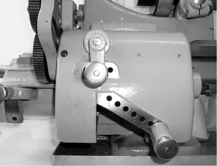
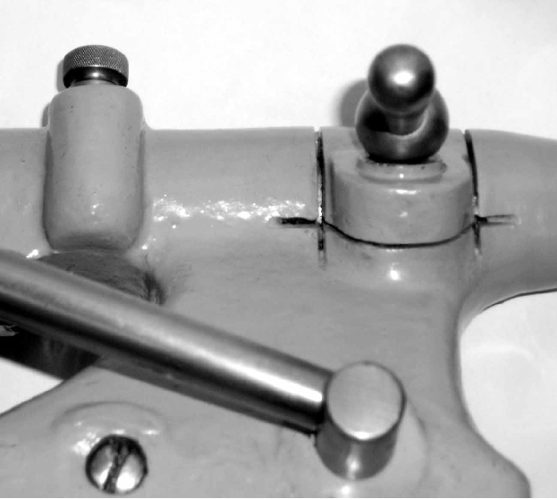
The drive could be instantly disengaged either by an automatic mechanism, tripped by a block locked into a slot that ran down the front face of the bed, or manually by a button on the front face of the apron
|
|
|
|
|
|
|
 |
|
|
|
|
|
|
|
|
A full screwcutting and feeds gearbox was fitted that, in conjunction with a primary gearbox, gave a total of 140 pitches - and feeds from 0.075 mm to 3.4 mm per revolution of the spindle. The first box was controlled by a selector that slid into and out of the end face and a two-position lever on its front whilst the second contained a conventional tumbler arrangement under the control of a lever engaged in a serious of 7 holes together with a 3-position lever to select left and right-hand travel of the carriage.
|
|
|
|
|
|
|
|
|
|
|
|
|
|
 |
|
|
|
|
 |
|
|
|
|
|
The primary box was fitted with just a loose cover - to allow the injection of oil - with a screw-in grease lubricator for the shaft bearings
|
|
|
|
|
|
|
 |
|
|
|
|
 |
|
|
|
|
|
|
|
|
|
 |
|
|
|
|
|
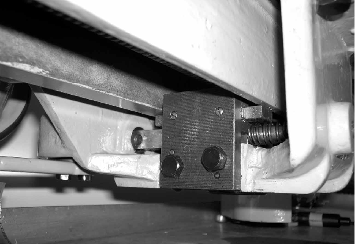
The "apron" was in the form of an open-topped box and bolted to both front and back of the saddle thus forming a rigid, enclosed structure to support the leadscrew clasp nuts (shown below) carried on a heavy, bolt-on housing
|
|
|
|
|
|
|
 |
|
|
|
|
|
|
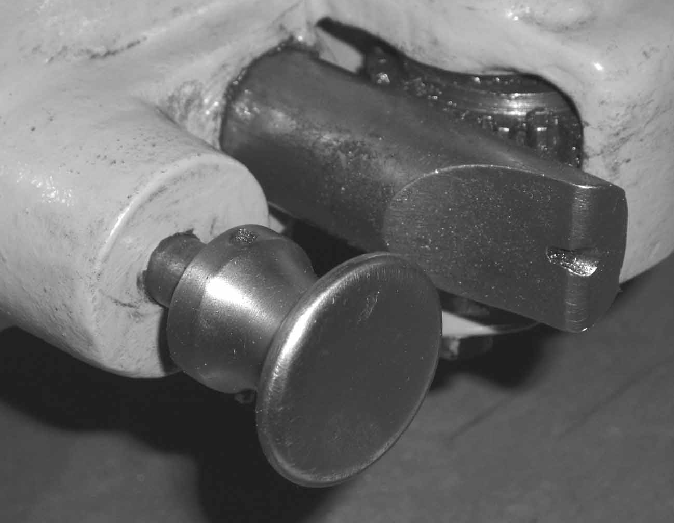
The bronze clasp nuts were engaged by a Boley-like lever beneath the apron working through a rack-and-pinion arrangement (shown below) and with an over-centre type lock
|
|
|
|
|
|
|
 |
|
|
|
|
 |
|
|
|
|
|
|
The same flat-topped, bevelled-edged central section of the bed with its central slot was shared by headstock and tailstock
|
|
|
|
|
|
|
|
|
|
|
|
 |
|
|
|
|
|
|
|
|
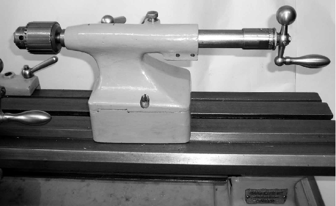
The tailstock looked as though it had been lifted from one of the maker's precision plain-turning lathes (which in all probability it) and was typical of the type in having a barrel that was always fully supported within the casting no matter what its position. Its sole plate was enormously thick and of the kind once described as: "built up in the sand" - a reference to the likelihood that its manufacture had been quickly and crudely altered at the casting rather than pattern-making stage
|
|
|
|
|
|
|
|
|
 |
|
|
|
|
 |
|
|
|
|
|
|
|
|
Unfortunately, the barrel locking arrangement was the crude type that relied upon a slot in the casting being closed down by a screw - a system that normally leads to breakages when the unit becomes worn. However, on the Swisten, this usually poor arrangement was better engineered with both longitudinal and vertical slots being used to isolate a small section of casting that could be clamped with greater pressure than would otherwise have been possible.
|
|
|
|
|
|
|
|
|
 |
|
|
|
|
|
|
|
|
|
A fine example of a home-made countershaft: solidly built and with a strong mechanism to slacken and tension the headstock spindle drive belt
|
|
|
|
|
|
|
|
|
|
|
|
|
|
|
|
|