E-Mail Tony@lathes.co.uk 
Home    Machine Tool Archive    Machine Tools For Sale & Wanted
Machine Tool Manuals  Catalogues   Belts   Accessories


TOS and MAS SV-18RA, SV-18RB
& SV-18RD Lathes

Zbrojovka SV-18R Lathe

Literature is available for this lathe and can be ordered here

TOS Machine Tools Home Page

Closely based on the long-established SV-18R (first offered during 1957), the newer SV-18RA, SV-18RB and SV-18RD models used the same headstock, and carriage assembly - but with (variously) a modified screwcutting and feeds' gearbox, new drive systems and the major castings and stand given a more up-to-date angular appearance. Introduced in the mid 1960s with an initial choice of 500, 1000, 1250 mm between centres (750 mm was to be added later), the first of the new versions was the SV18RA; this retained the plinth-mounted 12-speed spindle-drive gearbox of the original type but had the essential electrical controls moved from the tailstock-end plinth to be grouped neatly together  (as push-buttons and warning lights) within easy reach on the headstock's front face. Almost unchanged, the flat-belt-driven headstock was as robust as ever, driven by a 2800 r.p.m. 8 h.p. motor and with the same twenty-one speeds from a low of 14 to a high of 2800 r.p.m.
One significant alteration was to the screwcutting and feeds gearbox, the previous open tumbler selector being replaced by a star handwheel on the front enabling the box to be fully sealed and fitted with its own eccentrically driven piston pump instead of sharing oil fed to the headstock (though this particular modification is suspected to have been introduced, though not announced, on the earlier model). On the SV-18RA (but not the SV-18RB and SV-18RD) the arrangement of drive gears was also modified so as to vastly increase the number of feeds and pitches available. By using sets of alternative changewheels up to 228 feeds from 0.02 to 5.6 mm per revolution of the headstock spindle (with surfacing feeds at half those rates) could be generated - as well as 156 metric pitches from 0.2 to 140 mm, 211 English pitches from 140 to 1/5th t.p.i., 126 DP pitches from 1 to 224 and 101 Module from 0.2 to 70.
Continued below:

TOS SV-18RA - first of the updated models

Continued:
Although the V-way bed (carried over from the early model) was deep, massively constructed (without a gap to weaken it) heavily cross-ribbed and supplied hardened as standard it was "only" 13.5 inches wide and so just short of the 15 inches that would have made the traditionalists happy who insist that, to qualify  it as a "toolroom" lathe, the width must be equal to, or greater than, twice the centre height. Flat and V-ways were used, the V at the front reflecting a fashion of the time where the outer part of the way (to better absorb wear) was much wider and set at a shallower angle than the steeper, shorter inner side that took the tool thrust. Because the bed ways ran past the front and back of the headstock the carriage was able to have its cross slide to be mounted properly on the centre line - yet the cutting tool could still be run right up to the spindle nose without having to advance the tool slide beyond it normal position.
Carrying the bed were two suitably large and heavy cast-iron plinths, separated by a large slide-out chip tray, with that under the headstock end holding the powerful, 2800 r.p.m., 8 h.p. motor bolted to the spindle speed-change gearbox and driving it by five V-belts - drive to the headstock pulley being by an enormously wide, smooth-running flat belt. With such power available (a 5 h.p. motor would have been the expected fitting for a lathe of this size) the makers wisely decided to fit a large Ampere-meter, in the front face of the headstock; to advise the operator against the danger of overloading at slow spindle speeds; it was marked in red to show 14, 22, 35 and 56 rpm with contrasting black numbers advising the maximum horse power that could be used at each setting.  Control of speeds was by a handwheel (as used on the American Monarch 10EE and English CAV lathes) with a cut-out in its face to reveal the r.p.m. selected. The remote gearbox and motor installation had the effect of removing all but the low-speed backgears from within the headstock and was intended both to simply the design and also reduce marks on finely finished surfaces caused by gear thrash induced vibrations.
Running in finely adjustable bronze bearings (with axial ball-bearing thrust races), the hardened and ground high-tensile steel headstock spindle had homed bearing surfaces, was bored through to clear 31 mm (1.625") with a metric No.5 0 internal taper (sleeved to a No. 3 Morse) and a threaded nose to the specification M68.
In order to avoid belt pull affecting the spindle, the headstock pulley ran in its own ball races, the drive being transmitted by a key. Twenty-one spindle speeds were available that covered a very wide range - from 14 to 2800 r.p.m. - with those up to 355 r.p.m. being driven through the headstock mounted 8 : 1 ratio backgear and the rest direct by belt from the gearbox output pulley. Instead of a mechanical device, braking of the spindle was achieved by selecting motor reverse - the effect being powerful enough to bring a heavy job to a halt with surprising speed. Lubrication was very effective, being delivered by an electricaly-driven gear pump mounted on top of a 7 litre tank within the headstock-end plinth with a supply fed to the screwcutting and feeds' gearbox and to the spindle - the flow being copious enough to keep bearing temperatures down even when using high speeds for extended periods. Because the pump started work as soon as the lathe motor was switched on it was possible for the operator to ensure that oil was flowing (through two inspection windows on top of the headstock, directly above the bearings) before committing the machine to work.

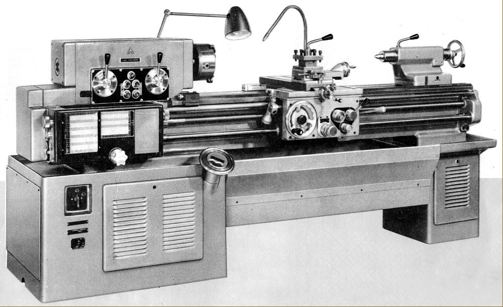
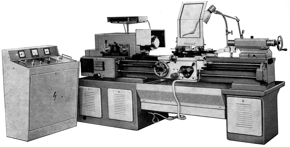
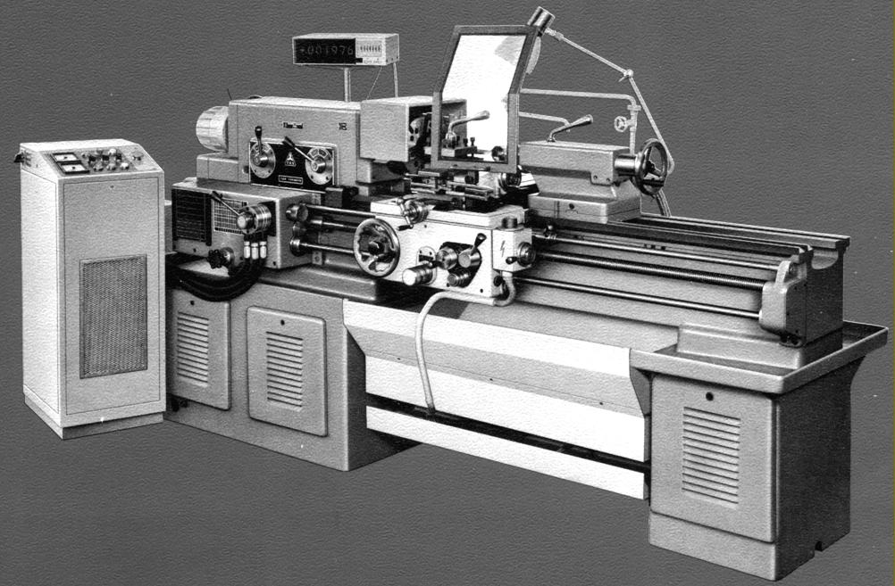
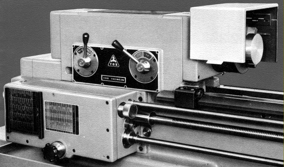
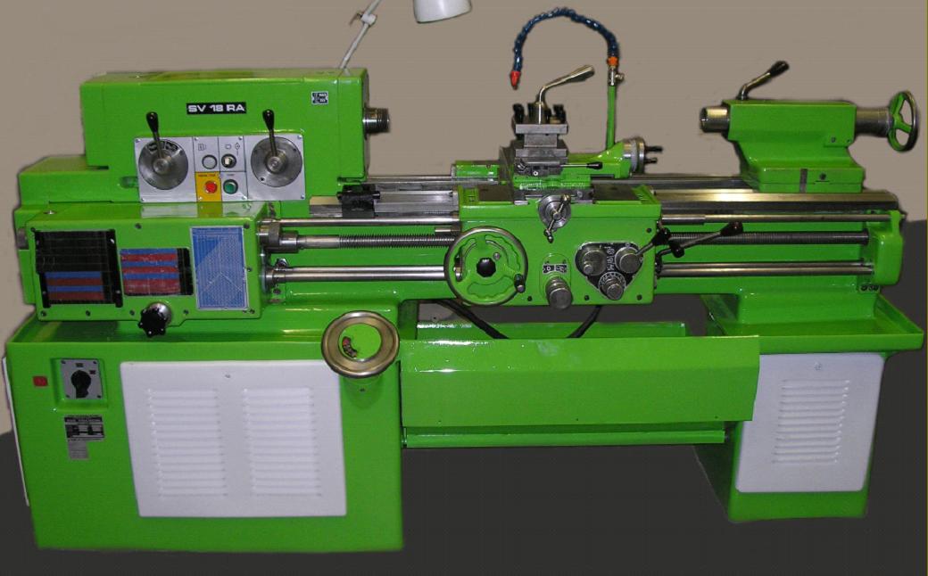
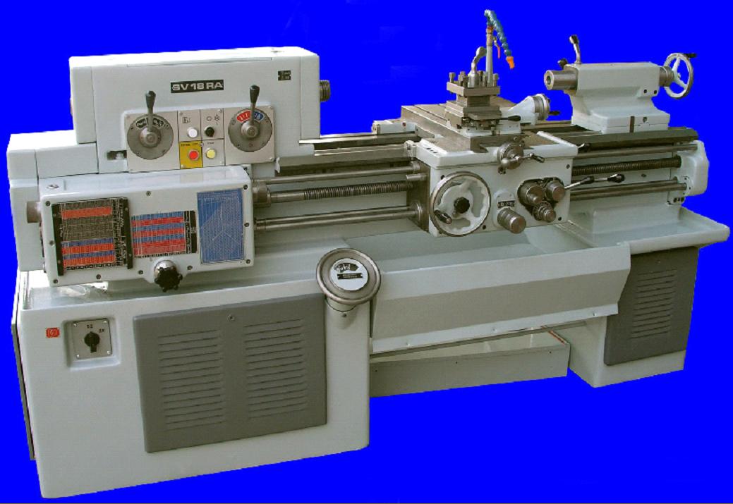
Circa 1974 TOS SV-18RB - first of the variable-speed drive types with its electrical cabinet and fitted with an early DRO system

Continued:
As the tailstock-end plinth had the switches for main and coolant motors, light and warning bulbs built into its front face (a dangerously remote location in the event of an emergency) control of the spindle start, stop and reverse was by a "third-rod" system with the operating lever pivoting from the apron's right-hand face.
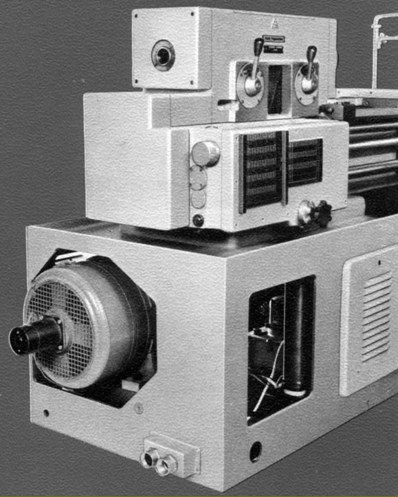
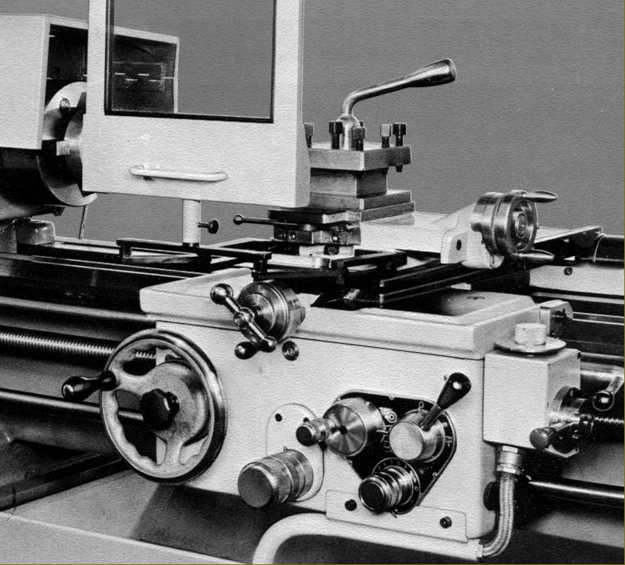
Of unusual arrangement and very compact, the screwcutting and feeds' gearbox had snail-cam selectors moved by two handwheels, one on each end face of the box, together with a starwheel on the front face and a headstock-mounted lever that switched between coarse and fine pitches. As mentioned previously, this box and its changewheel drive was able to generate many more pitches and threads than the previous tumbler-equipped version.
Sliding and surfacing feeds were each fitted with positive stops that, when run against, caused an apron-mounted clutch to slip - the same device acting to provide safety overload protection. The release pressure of the clutch could be set by the operator, a graduated dial being provided on the apron's face below and to the left of the feeds' and leadscrew clasp-nut controls. Instead of the usual headstock-mounted drive-reverse gearing, this mechanism (a single-tooth clutch) was incorporated within the apron - the operation lever being on the tailstock-end face. Fitted with a neat, face-locked micrometer dial, the carriage handwheel could, as a handy safety measure, be disengaged when power feeds were in use.
Both cross and top slide were fitted with proper taper-gib strips (with front adjuster and back stop screws) and, unusually, for a lathe of this type and size, the cross slide carried two T slots that ran front to back in the manner once common on smaller Austrian-built Emco screwcutting lathes. Fitted with such T slots the cross slide could be much more easily and quickly adapted to carry a range of accessories including a rear toolpost, travelling steady, ball-turning attachment or a powered, high-speed milling or grinding head. The compound-slide zeroing micrometer dials were not as large as they should have been yet, surprisingly, the makers went to the trouble of arranging the top slide feed-screw with an intermediate 'step-up' gear that allowed the dial to be set above the slide's top surface and so made larger and easier to read. To assist with screwcutting the toolpost was fitted with an independent quick-withdrawal mechanism whereby the tool could instantly pulled back but then returned to the exactly same position, ready to apply a little more cut, when the carriage had been wound back to the start point.
Of ordinary design, the set-over tailstock had a hardened, ground and lapped spindle with a 120 mm (4.75") stroke, a No. 3 Morse taper socket, metric ruler graduations and a large-diameter zeroing micrometer dial. A proper split-cylinder clamp locked the spindle and the whole assembly was secured to the bed by a lever-operated eccentric cross shaft (though it lacked a second bolt to help with heavy work).
Supplied as standard with each new machine were: a complete electrical installation, ready to run; two No.3 Morse centres; coolant equipment; ordinary radial-slotted faceplate, fixed steady, travelling steady, one simple stop for the carriage feed; two stops for the cross feed; a chuck backplate, a set of spanners and an operator's handbook.
SV-18RB and SV-18RD
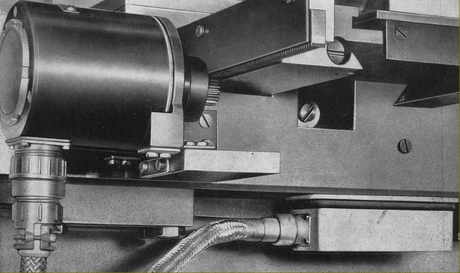
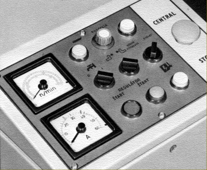
First sold during 1974, the SV-18RB was fitted with a massive, infinitely variable-speed (thyristor controlled) 13.5 h.p. DC motor. Instead of passing through a gearbox (as on the SV-18RA), the drive to the spindle was now direct from the motor pulley using the same wide flat belt as before. Although immediate electrical control of the lathe was simplified to a dial-equipped potentiometer fastened to the apron's right hand wall, with a built-in start/stop switch, the rest of the new electrical system required housing in a separate cabinet, the face of which housed the necessary main switchgear, push-button controls, warning lights and both ammeter and torque gauges. With the later introduction of the SV-RD (there appears to have been no SV-RC, the SV-18RD and SV-18A appearing in the same catalogue) the electrical cabinet was made smaller, the control panel improved and electrical details tidied up.
An interesting option made available by the variable-speed drive was a NC controlled mechanism that provided, via a precision backlash-free rack and electric motor, a constant cutting speed when facing - a decided advantage on large-diameter components that led to much improved surface finishes and reduced machining time. A switch on the control cabinet was provided to select manual or automatic constant-cutting spindle speeds - in the latter setting the speed being increased steplessly in such a manner that it reached its maximum of 2800 rpm near the centreline of the job. The control components consisted of a pick-up mounted on the cross slide, an amplifier, potentiometers for the rate of cutting and correction of the tool position in relation to the cross slide and indicator bulbs that showed how the correction of position was to be made.
Using exactly the same screwcutting and feeds' as the original SV-18R (and not the newer, improved box from the SV-18RA) it was possible, by dint of using alternative changewheels, to generate 127 metric, 188 English, 81 MOD and 70 Diametral pitches and 128 rates of feed 0.02 to 5.6 mm per revolution of the headstock spindle sliding and at half those rates surfacing..

TOS SV-18RD fitted with constant-speed power cross-feed

Continued:
Of ordinary design, the set-over tailstock had a hardened, ground and lapped spindle with a 120 mm (4.75") stroke, a No. 3 Morse taper socket, metric ruler graduations and a large-diameter zeroing micrometer dial. A proper split-cylinder clamp locked the spindle and the whole assembly was secured to the bed by a lever-operated eccentric cross shaft (though it lacked a second bolt to help with heavy work).
Supplied as standard with each new machine were: a complete electrical installation, ready to run; two No.3 Morse centres; coolant equipment; ordinary radial-slotted faceplate, fixed steady, travelling steady, one simple stop for the carriage feed; two stops for the cross feed; a chuck backplate, a set of spanners and an operator's handbook.
Accessories remained identical to those from earlier years: taper turning; 3 and 4-jaw chucks; a faceplate-cum 4-jaw chuck with radial sots and four T-slots to carry jaws; 4-way and quick-set toolholders; thread-dial indicator; micrometer stops for the carriage and cross feed; collet chuck with the usual range of round, square and hexagon collets with bores from 2 to 25 mm; a stepped master chuck (conical type) to hold outside clamping collets (five supplied from 20 to 64 mm); a stepped oversize master collet chuck (fit-tree type) for inside clamping with five collets from 35 to 80 mm; a second top slide unit; rear 4-way toolpost; angle plates a light unit and a most unusual spindle-nose fitting: an angle plate mounted on a compound slide rest..

The massive 10 kW DC motor fitted to the variable-speed models

Drive to the spindle on the variable-speed models was direct by flat belt

Apart from the addition of a dial-equipped potentiometer fastened to its right hand wall (to control spindle speed) the carriage of the last SV-18RD models was identical to those made in 1957

Underneath the rear of the cross slide - part of the constant-speed feed mechanism

TOS SV-18RD--headstock and screwcutting and feeds' gearbox

Late-type control panel used on the floor-standing unit

TOS SV-18RA

TOS SV-18RA

Zbrojovka SV-18R Lathe

TOS Machine Tools Home Page

Literature is available for this lathe and can be ordered here

TOS and MAS SV-18RA, SV-18RB
& SV-18RD Lathes