 |
|
|
|
|
|
|
|
|
|
|
|
|
|
|
|
|
|
|
|
|
|
|
|
|
|
|
|
|
|
|
|
|
|
|
|
|
|
|
|
|
|
|
|
|
|
|
|
|
|
|
|
|
|
|
|
|
|
|
|
|
|
|
|
|
|
|
|
|
|
|
|
|
|
|
|
|
|
|
|
|
|
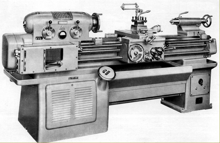
Introduced in 1957 - and made until the mid 1960s in what used to be Czechoslovakia by the communist, state-controlled TOS/Skoda machine-tool group - the 190 mm (7.5") centre height by x 750, 1000 or 1250 mm (30", 40" or 50") between-centres "Zbrojovka" SV-18R lathe was sold in the UK (initially through Elgar machine tools of Feltham, Middlesex) using three different brands: Zbrojovka, TOS and MAS. At a time when the Eastern Block countries and the USSR were desperate for Western currency the lathe was offered at a very competitive price, just £1336 in 1957. The machine enjoyed considerable success and the design (using unaltered main components) was continued into the 1980s as the Models SV-18RA, SV-18RB and SV-18RD, though with the styling given a more modern, angular look and a number of improvements made to the drive and lubrication systems.
Although the V-way bed was deep, massively constructed (without a gap to weaken it) heavily cross-ribbed and supplied hardened as standard it was "only" 13.5 inches wide and so just short of the 15 inches that would have made the traditionalists happy who insist that, to qualify it as a "toolroom" lathe, the width must be equal to, or greater than, twice the centre height. Flat and V-ways were used, the V at the front reflecting a fashion of the time where the outer part of the way (to better absorb wear) was much wider and set at a shallower angle than the steeper, shorter inner side that took the tool thrust. Because the bed ways ran past the front and back of the headstock the carriage was able to have its cross slide to be mounted properly on the centre line - yet the cutting tool could still be run right up to the spindle nose without having to advance the tool slide beyond it normal position.
Carrying the bed were two suitably large and heavy cast-iron plinths, separated by a large slide-out chip tray, with that under the headstock end holding the powerful, 2800 r.p.m., 8 h.p. motor bolted to the spindle speed-change gearbox and driving it by five V-belts - drive to the headstock pulley being by an enormously wide, smooth-running flat belt. With such power available (a 5 h.p. motor would have been the expected fitting for a lathe of this size) the makers wisely decided to fit a large Ampere-meter, in the front face of the headstock; to advise the operator against the danger of overloading at slow spindle speeds; it was marked in red to show 14, 22, 35 and 56 rpm with contrasting black numbers advising the maximum horse power that could be used at each setting. Control of speeds was by a handwheel (as used on the American Monarch 10EE and English CAV lathes) with a cut-out in its face to reveal the r.p.m. selected. The remote gearbox and motor installation had the effect of removing all but the low-speed backgears from within the headstock and was intended both to simply the design and also reduce marks on finely finished surfaces caused by gear thrash induced vibrations.
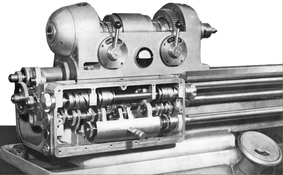
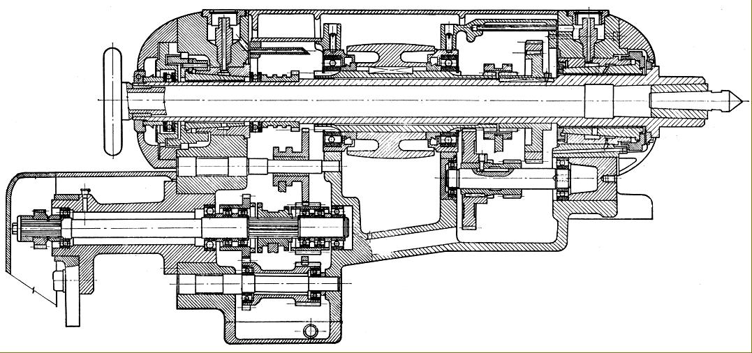
Running in finely adjustable bronze bearings (with axial ball-bearing thrust races), the hardened and ground high-tensile steel headstock spindle had homed bearing surfaces, was bored through to clear 31 mm (1.625") with a metric No.5 0 internal taper (sleeved to a No. 3 Morse) and a threaded nose to the specification M68.
In order to avoid belt pull affecting the spindle, the headstock pulley ran in its own ball races, the drive being transmitted by a key. Twenty-one spindle speeds were available that covered a very wide range - from 14 to 2800 r.p.m. - with those up to 355 r.p.m. being driven through the headstock mounted 8 : 1 ratio backgear and the rest direct by belt from the gearbox output pulley. Instead of a mechanical device, braking of the spindle was achieved by selecting motor reverse - the effect being powerful enough to bring a heavy job to a halt surprisingly quickly. Lubrication was very effective, being delivered by an electricaly-driven gear pump mounted on top of a 7 litre tank within the headstock-end plinth with a supply fed to the screwcutting and feeds' gearbox and to the spindle - the flow being copious enough to keep bearing temperatures down even when using high speeds for extended periods. Because the pump started work as soon as the lathe motor was switched on it was possible for the operator to ensure that oil was flowing (through two inspection windows on top of the headstock, directly above the bearings) before committing the machine to work.
As the tailstock-end plinth had the switches for main and coolant motors, light and warning bulbs built into its front face (a dangerously remote location in the event of an emergency) control of the spindle start, stop and reverse was by a "third-rod" system with the operating lever pivoting from the apron's right-hand face.
Continued below:
|
|
|
|
|
|
|
|
|
|
|
|
|
 |
|
|
|
|
|
|
Continued:
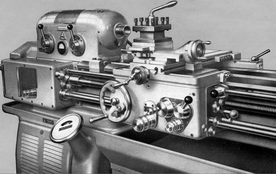
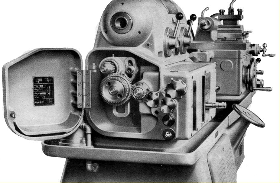
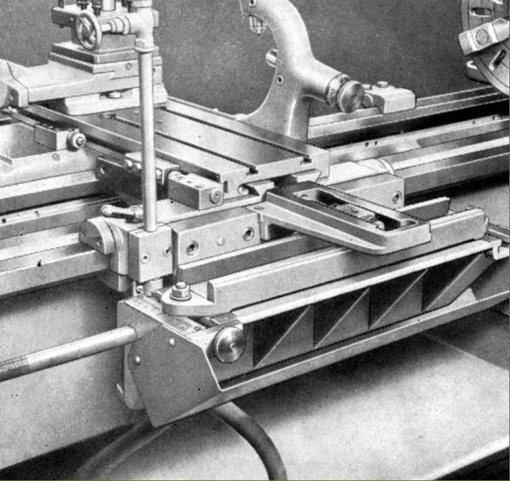
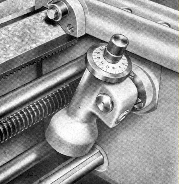
Of unusual arrangement and very compact, the screwcutting and feeds' gearbox had snail-cam selectors moved by two handwheels, one on each end face of the box, together with the usual sliding tumbler mechanism and a headstock-mounted lever that switched between coarse and fine pitches. By using alternative changewheels the box was able to generate 127 metric, 188 English, 81 MOD and 70 Diametral pitches and 128 rates of longitudinal feed from 0.02 to 5.6 mm per revolution of the headstock spindle with surfacing feeds at half those rates. The extra gears required to enable the complete range of threads to be cut were (as far as can be determined) 2 x 24T, 48t, 60t, 71t and 113t. Sliding and surfacing feeds were each fitted with positive stops that, when run against, caused an apron-mounted clutch to slip - the same device acting to provide safety overload protection. The release pressure of the clutch could be set by the operator, a graduated dial being provided on the apron's face below and to the left of the feeds' and leadscrew clasp-nut controls. Instead of the usual headstock-mounted drive-reverse gearing, this mechanism (a single-tooth clutch) was incorporated within the apron - the operation lever being on the tailstock-end face. Fitted with a neat, face-locked micrometer dial, the carriage handwheel could, as a handy safety measure, be disengaged when power feeds were in use.
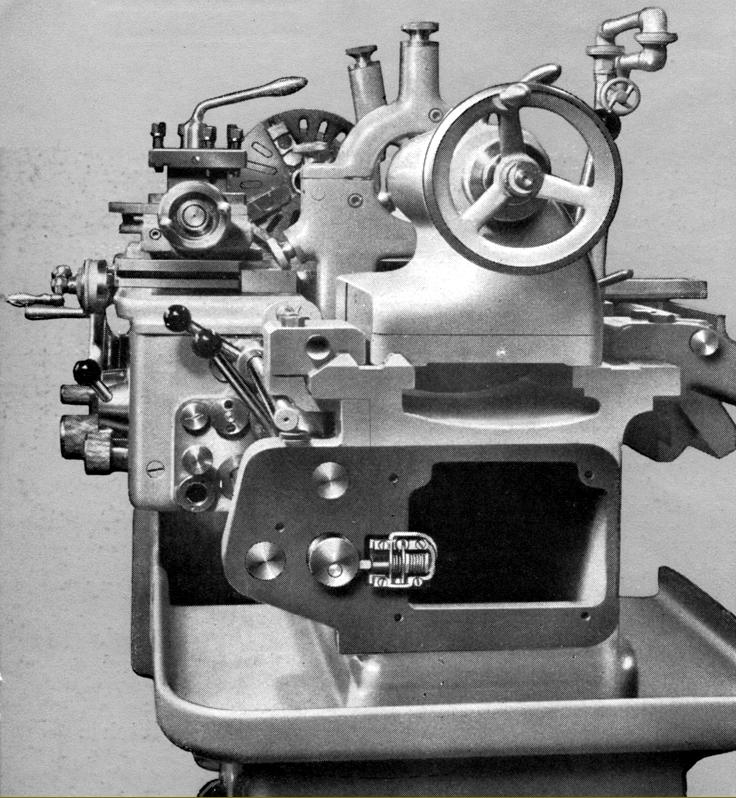
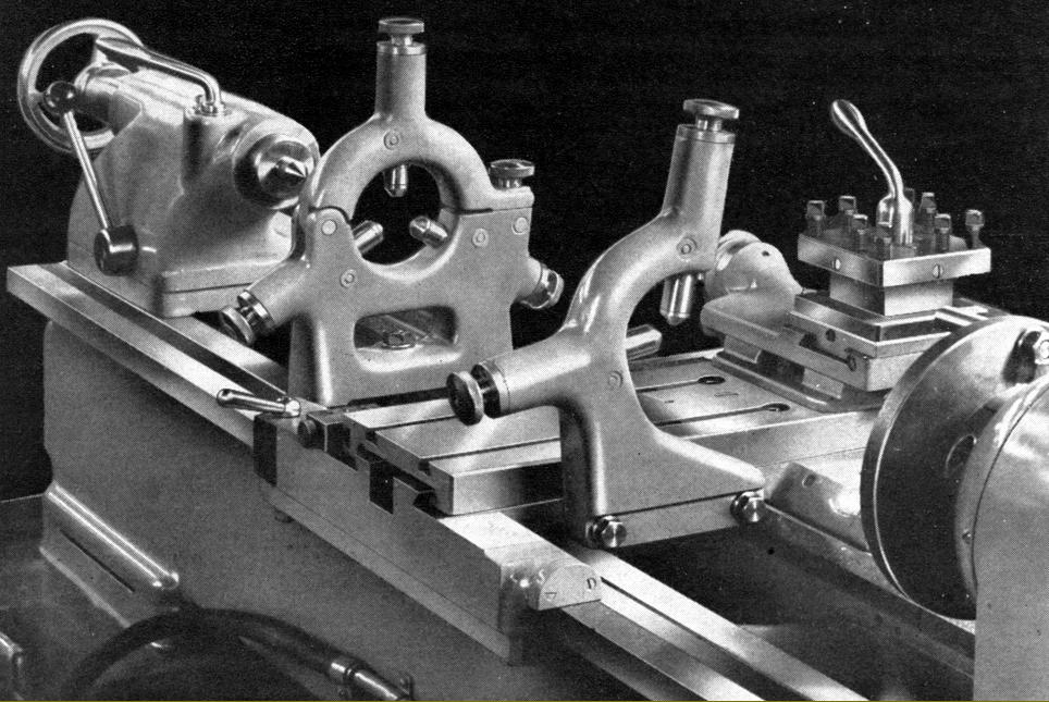
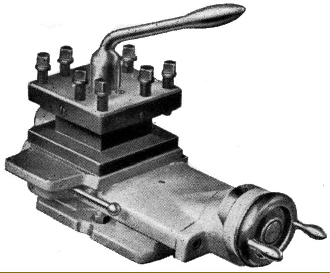
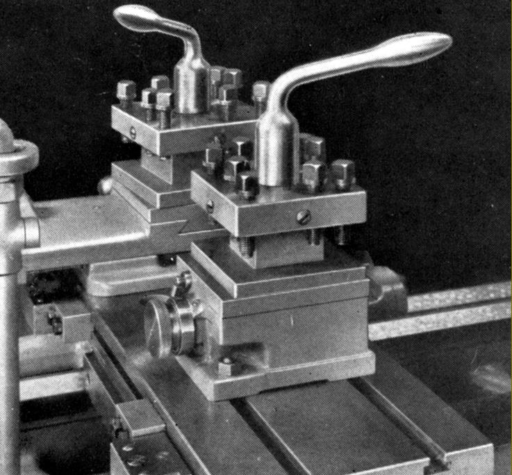
Both cross and top slide were fitted with proper taper-gib strips (with front adjuster and back stop screws) and, unusually, for a lathe of this type and size, the cross slide carried two T slots that ran front to back in the manner once common on smaller Austrian-built Emco screwcutting lathes. Fitted with such T slots the cross slide could be much more easily and quickly adapted to carry a range of accessories including a rear toolpost, travelling steady, ball-turning attachment or a powered, high-speed milling or grinding head. The compound-slide zeroing micrometer dials were not as large as they should have been yet, surprisingly, the makers went to the trouble of arranging the top slide feed-screw with an intermediate 'step-up' gear that allowed the dial to be set above the slide's top surface and so made larger and easier to read. To assist with screwcutting the toolpost was fitted with an independent quick-withdrawal mechanism whereby the tool could instantly pulled back but then returned to the exactly same position, ready to apply a little more cut, after winding the carriage back to the start point.
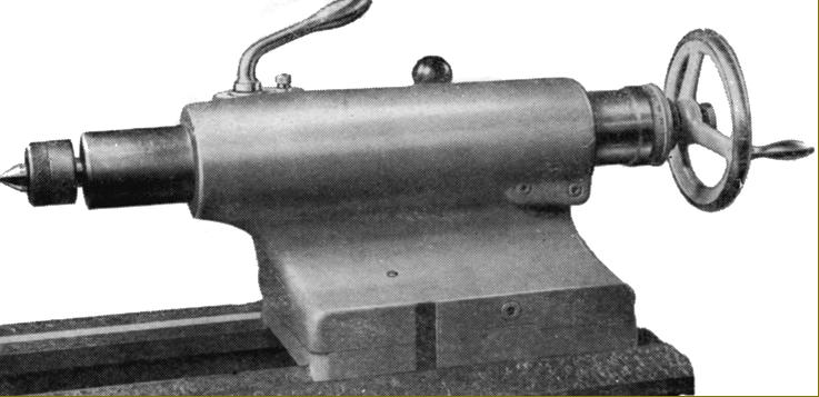
Of ordinary design, the set-over tailstock had a hardened, ground and lapped spindle with a 120 mm (4.75") stroke, a No. 3 Morse taper socket, metric ruler graduations and a large-diameter zeroing micrometer dial. A proper split-cylinder clamp locked the spindle and the whole assembly was secured to the bed by a lever-operated eccentric cross shaft (though it lacked a second bolt to help with heavy work).
Supplied as standard with each new machine were: a complete electrical installation, ready to run; two No.3 Morse centres; coolant equipment; ordinary radial-slotted faceplate, fixed steady, travelling steady, one simple stop for the carriage feed; two stops for the cross feed; a chuck backplate, a set of spanners and an operator's handbook.
Accessories included the expected items: taper turning; 3 and 4-jaw chucks; a faceplate-cum 4-jaw chuck with radial sots and four T-slots to carry jaws; 4-way and quick-set toolholders; thread-dial indicator; micrometer stops for the carriage and cross feed; collet chuck with the usual range of round, square and hexagon collets with bores from 2 to 25 mm; a stepped master chuck (conical type) to hold outside clamping collets (five supplied from 20 to 64 mm); a stepped oversize master collet chuck (fit-tree type) for inside clamping with five collets from 35 to 80 mm; a second top slide unit; rear 4-way toolpost; angle plates a light unit and a most unusual spindle-nose fitting: an angle plate mounted on a compound slide rest..
|
|
|
|
|
|
|
 |
|
|
|
|
 |
|
|
|
|
|
|
|
|
|
 |
|
|
|
|
|
|
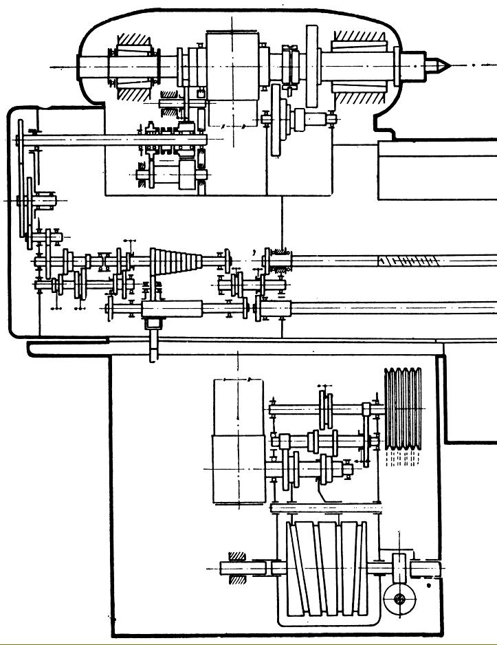
Drive system diagram SV-18R
|
|
|
|
|
|
|
 |
|
|
|
|
|
SV-18R - section through headstock showing clearly the plain-bore, tapered outside spindle bearings and the drive pulley supported in its own ball races
|
|
|
|
|
|
|
 |
|
|
|
|
 |
|
|
|
|
|
|
Forward, reverse and neutral electrical switch was mounted inside the tailstock end of the bed
|
|
|
|
|
|
|
|
|
|
|
|
 |
|
|
|
|
 |
|
|
|
|
|
|
Fixed and travelling steadies
|
|
|
|
|
|
|
 |
|
|
|
|
Of conventional design, the set-over tailstock had a hardened, ground and lapped spindle with a 120 mm (4.75") stroke, a No. 3 Morse taper socket, metric ruler graduations and a large-diameter zeroing micrometer dial. A proper split-cylinder clamp locked the spindle and the whole assembly was secured to the bed by a lever-operated eccentric cross shaft (though it lacked a second bolt to help with heavy work).
|
|
|
|
|
|
|
|
|
|
|
|
 |
|
|
|
|
|
|
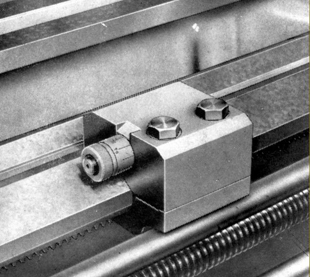
The toolpost was fitted with a quick-withdrawal lever for use when screwcutting
|
|
|
|
|
|
|
 |
|
|
|
|
|
|
|
|
 |
|
|
|
|
|
|
|
|
|
|
|
|
|
|
|
 |
|
|
|
|
|
|
|
|
|
|
 |
|
|
|
|
|
|
|
|
|
|
 |
|
|
|
|
|
|
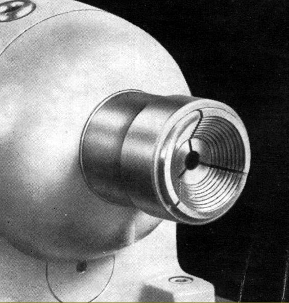
Spindle-nose adapter to take the cone collets
|
|
|
|
|
|
|
 |
|
|
|
|
|
|
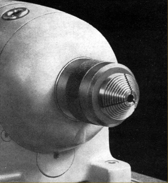
Spindle-nose adapter to take the fir-tree collets
|
|
|
|
|
|
|
|
|
|
|
|
 |
|
|
|
|
|
|
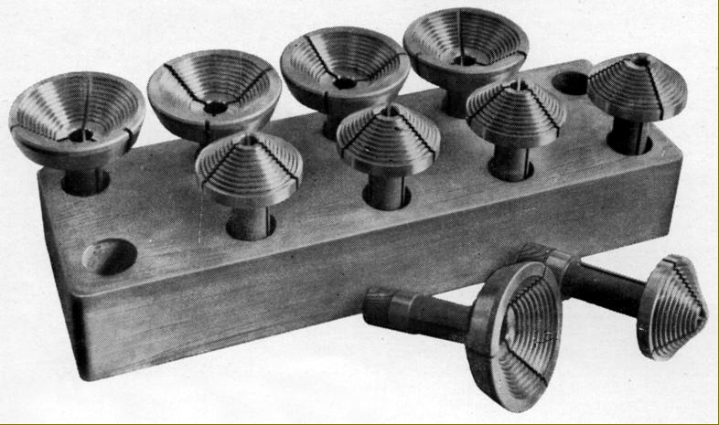
Cone and fir-tree collet set
|
|
|
|
|
|
|
 |
|
|
|
|
|
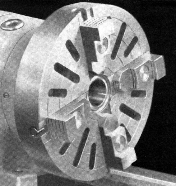
Typical faceplate-cum-4-jaw chuck as supplied by many continental makers until the late 1960s
|
|
|
|
|
|
|
 |
|
|
|
|
|
|
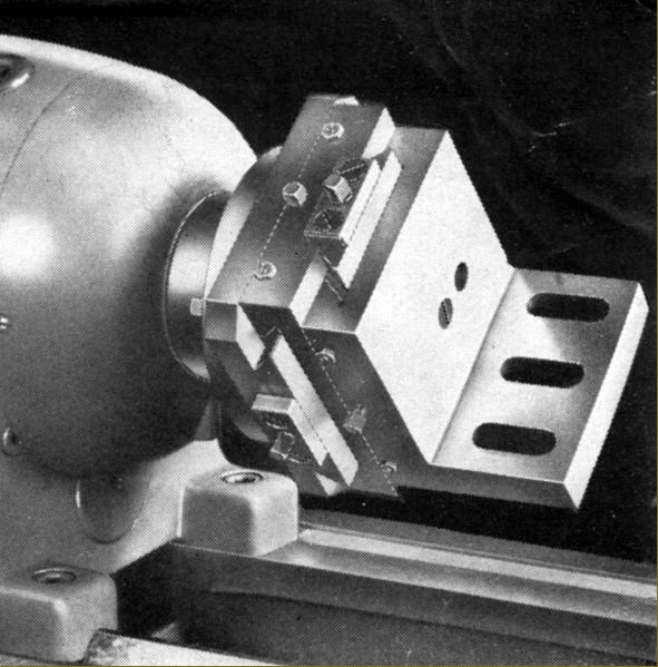
A most unusual spindle-nose fitting: an angle plate mounted on a compound slide rest
|
|
|
|
|
|
|
|
|
|
|
|
|
|
|