email: tony@lathes.co.uk
Home   Machine Tool Archive   Machine-tools Sale & Wanted
Machine Tool Manuals   Catalogues   Belts   Books  Accessories

Willson Lathes (Smith, Barker & Willson)
Willson Slant-Bed Lathe - Elliott "Ensign" Lathe
Willson Slant Bed Continued Here

Willson Early 7.5/8.5-inch    Other Willson Lathes: 7.5", 8.5", 10.5" & 12.5"

Willson-Elliott 1N Lathe    8.5" "Pitel" & "Pitag" Lathes   Wilson History   Willson Spinning Lathes

Big Slant Bed listed as the Mk.11   1960s New-model 11-inch

A copy of the maker's Manual & Parts List for the Slant-bed
is available and for other Willson Lathes

At one time a prominent English maker, the Willson Company was based, together many other machine-tool concerns, in the Halifax area of Yorkshire. Willson's proud slogan, probably conjured up by long-term employee Sam Staff, was "We nobbut mak lathes!" (we make nothing but lathes). The firm was started in 1897 by three unemployed engineers: George Willson, Edwin Barker and Fred Smith and they began, as did so many others before and since, by renting unsuitable premise - in their case in a too-dark cellar under a warehouse for five shilling a week. A bank loan of £100 helped the new enterprise of "Smith, Barker and Willson" towards the inevitable expenses of launching their venture - and one of the three was prevailed upon to loan his personal lathe for Company use. Being unable to afford more machinery they first used the lathe, plus an amount of scrap metal, to manufactured both a planer and a horizontal borer, so greatly extending the type and size of work they were able to take in. Their first commercial product was a well-received if entirely conventional lathe - and its success made the decision for them to concentrate on this competitive segment of the market. By 1902 they had moved out of the cellar and into part of a weaving shed - where the great improvement in light quality must have come as a great relief. In days before electric illumination, factories needed not only large windows to admit as much daylight as possible, but also, if the working day was to be a long one, a south-facing site as well. Installed in the new premises the three men bought a gear-cutting machine, vertical and horizontal millers and a cylindrical grinder; thus equipped, the company was now ready to share in the general prosperity in the years leading up to the start of the First World War, in 1914. By 1913 the business was so successful that they had taken over the whole of the weaving shed and, in the two years preceding the outbreak of WW1 in 1914, were turning out 250 lathes a year - though by 1918, in the last year of the war (and under the pressure of its demands), output reached 600 per annum. Early lathes were not marked "Willson" but either  Smith Baker & Willson Halifax or SBW - when the change was made to using just "Willson" is not known, but even as late as 1921 the Mechanical World Year Book had advertisements listing the Company under its original title.
Despite introducing a lathe with a number of novel features in time for the Machine Tools Trade Exhibition of 1920, the early years of that decade were a time of slow machine-tool sales and the firm was forced to take on jobbing and sub-contract work and manufacture one-off machines for various trades unconnected with their usual business.
Fred Smith died in 1912 and Edwin Baker, who had acted as machine-shop foreman, retired in 1912; his place was taken by Mr. J. Richardson who went on to become first the Works Manager and then a Director until, after the retirement of Mr. Willson in 1932 and under a reorganisation, he together with George Willson (a son of the founder) and Albert Kitchen A.M.I.Mec.E,  dissolved
Smith Baker & Willson and founded a new Company "Willson Lathes." Mr. Richardson was now responsible for the practical aspects of lathe manufacture and, after the death of George Willson Junior in 1943, became managing Director. The Company went public in 1947, with Albert Kitchen as chairman, and were absorbed into the large Elliot Machine Tool Group in 1966.
Willson made an immense variety of lathes including specialised types such as their spinning models and more popular ones including the early 7.5 and 8.5-inch, the later and heavier 7.5, 8.5, 10.5 & 12.5-inch, a rare 12-inch centre height Slant Bed (listed as the Mk.11) the   8.5-inch "Pitel" & "Pitag" from the 1950s and the 1960s New-model 11-inch. However, the most common encountered today is the 7.5" x 24/36"  "Slant-Bed", a machine designed during the 1950s to appeal educational and training establishments. It was, in later years, exported in some numbers to America and Canada by the Elliot Company as the lightly-modified "Ensign" model (illustrated at the bottom of the page). The lathe had two unusual features: full enclosure of the leadscrew and power shaft behind a pair of spring-roller covers ( a Willson patent) and a bed with the hardened and ground ways arranged so that those at the front were well above those at the rear. The covered shafts at the front of the machine certainly appealed to safety-conscious colleges and training establishments (who bought many examples), but the only substantial claims made for the "inverted-V" inclined bed were the 17.5" turning capacity without the need for a gap and, "
good chip clearance away from the operator" with, in addition, long covers extended from the saddle to protect for the bed against swarf.

Early Slant-bed model with exposed spindle-speed levers and "straight-line" screwcutting gearbox

Continued:
Large enough to accept No. 5-Morse taper, the 1.5625" bore headstock spindle was sleeved down to 3-Morse (with the usual short taper sleeve) and the nose equipped with an American standard LO size taper-key nose - although early machines had a screw-thread nose. The spindle ran in taper-roller bearings and was driven by a single-speed, 2 h.p. 3-phase motor through 9 speeds spanning 52 to 954 rpm. As an option, on late models, a high-speed range from 84 to 1550 rpm could be specified or, with a two-speed 2 and 3 hp motor, 42 to 1550 rpm. A lever on top of the headstock operated a clutch when moved sideways and a spindle brake when pressed down; later versions were given an improved mechanism recognisable by a large quadrant-shaped housing surrounding the clutch-lever pivot point. Very late models also enjoyed an improvement to the spindle-speed selection levers where, instead of being vulnerable to accidentally engagement by a stray hand, had to be pressed inwards against spring pressure before they could be moved. On these lathes the clutch was removed and its operating lever used instead to operate an electrical switch and a brake--the effectiveness of which was proportional to the (firm) force exerted on its operating lever The system was combined with push button control - one each for forward and reverse and another for "inching" and all mounted on the front face of the changewheel cover. These late machines can easily be recognised by a sector-shaped speed-chart cover over the spindle speed levers.
13/8" in diameter, the 5 t.p.i leadscrew drove an oil-immersed screwcutting gearbox that gave 40 English and, with the deployment of a 125/127T pair, 8 metric threads (though one of these, being a non-standard 0.625 mm pitch, was there just to make up the numbers). Unusually for an affordable English-specification lathe of the period, the metric screwcutting was available "on demand" - this being achieved by bringing into mesh (by simply moving a single lever) the 125t gear that revolved on the same spindle as the 127 (the two gears, though having different numbers of teeth, were made the same diameter so they meshed with the 50t gear without having to adjust the setting of the changewheel bracket). Two extra gears, 49t and 54t, were available, if required, to further the metric threading range. On some versions, the sliding feed was fitted with an automatic knock-off control arranged by the simple expedient of mounting a sliding stop on the front edge of the trip tray that caught against the power-feed engagement lever that protruded from the base of the apron. One small problem concerned the engagement of the (single-sided) leadscrew clasp nut; the profile of the cam slot for closing it was so "abrupt" that it could be difficult to release under a heavy threading load. In addition the changewheel banjo was (incomprehensibly) pivoted at the wrong (driver) end, making it unnecessarily laborious to fit the substitute driver gears for metric pitches. Later-model slant-beds (before the sector-shaped spindle-speed covers) can be recognised by a revised screwcutting gearbox with its line of indent holes below rather than above the selector lever.
Cross and top slides were heavily built and equipped with thrust-bearing-equipped and particularly robust 3/4" x 5 t.p.i. feedscrews, a specification that promised slow wear and a long life. On some examples of the lathe an unusual cross and top-slide-gib arrangement was used where, instead of a loose gib strip and adjustment "pusher" screws, a pair of long gib "blocks" was fitted, each held into the roof of the slide by downward fitting screws with their heads counter-bored into the latter's top face. Unfortunately, unlike the similar arrangement used on a Myford Super 7, no sideways adjustment screws were fitted - indeed, no correction to the fit was possible, each section of gib block being simply scraped to a fit on its dovetail side and on the three thrust 'pads' that contacted the roof of the slide. As wear took place, and play developed, it would have been necessary to remove the bocks and effect repairs. One owner managed this by fitting ground shim stock under the gib blocks and then machining the mating faces to remove uneven wear and bring their underside of the loose to the same level as the dovetail on the other side. Side-mounted grub-screw were also fitted (along Super 7 lines) to enable fine adjustment and compensation for future wear.
Heavily built, the set-over tailstock had a No. 3 Morse taper barrel 11/2" in diameter and with a travel of 5 inches. Later lathes had a more robust unit with a V-shaped slideway formed between sole-plate and upper casting.
As appropriate for a machine intended for educational use a safety interlock was provided on the changewheel cover and, if the right-hand cupboard door was locked, the machine was electrically isolated. One useful feature not appreciated by owners who failed to read the
manual on page 12), was that as the splash-back cover was hinged down it formed a nifty swarf hopper. A wide range of accessories was offered, including some rather unusual ones.
Besides the expected range of accessories that included large faceplates, fixed and travelling steadies, collets, 4-way and quick-set toolholders, dead-length fixed and micrometer stops, a toolpost grinder, a vertical milling slide (etc), and one or two out-of-the-ordinary ones were also listed including a taper-turning and profiling attachment that could be used on the top slide, an unusually arranged hydraulic copying attachment and, strangest of all for a machine produced into the 1960s, a con-rod boring jig.
The 24-inches-between-centres lathe was 67" long, while the 36-inch capacity version was, naturally enough, 12 inches longer; the width was 36", the height 52" and the weight 1400 lbs and 1530 lbs respectively.
Shown on another page is a different version of the "Slant-Bed" - identical in almost all observable details but with the bed ways set level in the conventional way. This machine was branded (using the term "
straight bed") as both a Willson and, later, Elliott - in the latter case as the "Mark 1N" with a 7-inch centre height and, in what must have been the first type produced, as the 6.5-inch "Mark 1U".
From 1959 a now seldom-found 12-inch centre height Big slant bed listed as the Mk.11 manufactured, this having a 3-inch bore spindle with an L2 nose and 18 speeds from 12 to 580 r.p.m..

An early 1950s Willson 6.5" x  24" "Slant-Bed" with a large faceplate demonstrating the capacity of the lathe without the need for a gap.

The distinctive slant bed of the Willson lathe

A Slant-Bed being demonstrated in the factory

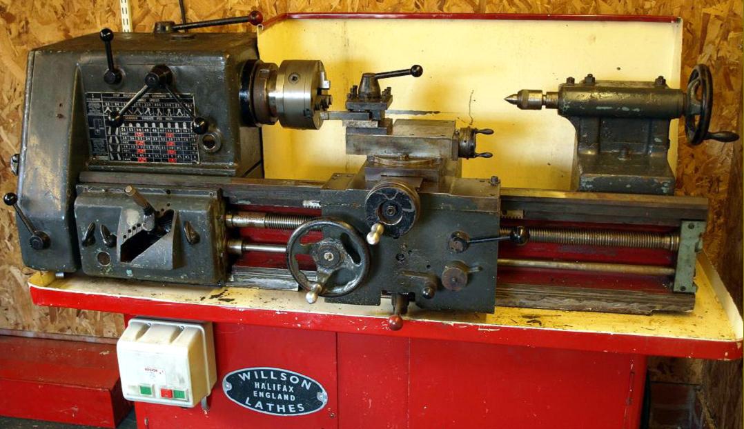
The carriage assembly was strongly built with a double-wall apron, a wide cross slide and the convenience of one lever to flick in and out the power sliding and surfacing speeds. Note the long swarf guides fitted to the saddle wings - a feature rarely found except on lathes of the highest quality.

A simple but robust headstock with splash lubrication and a robust American pattern L0 long-taper spindle nose.

The unusual form of the bed is clearly evident from this picture 

A Willson Slant-Bed fitted with both a later-type clutch and brake control and a safety catchplate with the drive dogs inside the cylinder

A 1960s Slant-Bed, badged as an "Ensign" with alterations to the protective blinds on the bed, a more massive tailstock, minor changes to the control levers and screwcutting gearbox - and sporting a "safety" catchplate on the spindle.

Spindle speed-change plate

Inside the screwcutting gearbox

Above and below:
being adaptable to both longitudinal and facing tapers  the Taper-turning and Forming Attachment could also be employed for simple contour-forming work - and thus may well have been a unique design. In the lefty-hand picture the top slide is bolted parallel to the cross slide, and the unit used to cut an internal taper.
In the right-hand illustration the unit is mounted in front of the top slide, and being employed to generate an inward taper towards the chuck.

Willson Slant Bed Continued Here

Willson Early 7.5/8.5-inch
   
Other Willson Lathes: 7.5", 8.5", 10.5" & 12.5"

Willson-Elliott 1N Lathe    8.5" "Pitel" & "Pitag" Lathes
 
Wilson History   Willson Spinning Lathes

Big Slant Bed listed as the Mk.11

   1960s New-model 11-inch

A copy of the maker's Manual & Parts List for the Slant-bed
is available and for other Willson Lathes


Willson Lathes (Smith, Barker & Willson)
Willson Slant-Bed Lathe - Elliott "Ensign" Lathe
email: tony@lathes.co.uk
Home   Machine Tool Archive   Machine-tools Sale & Wanted
Machine Tool Manuals   Catalogues   Belts   Books  Accessories