 |
|
|
|
|
|
|
|
|
|
|
|
|
|
|
|
|
|
|
|
|
|
|
|
|
|
|
|
|
|
|
|
|
|
|
|
|
|
|
|
|
|
|
|
|
|
|
|
|
|
|
|
|
|
|
|
|
|
|
|
|
|
|
|
|
|
|
|
|
|
|
|
|
|
|
|
|
|
|
|
|
|
|
|
|
|
|
|
|
|
|
|
|
|
|
|
|
|
|
|
|
|
|
|
|
|
|
|
|
|
|
|
|
|
|
|
|
|
What was to become the Wade Precision Bench Lathe was first produced in 1872 as the "No. 3" lathe of the American Watch Tool Company. To obtain high speeds with reliability and great accuracy, it used a headstock spindle and bearing assembly constructed along the lines of the company's "all-hard" watchmakers' lathes with a hardened spindle running in glass-hard bearings - this being the finest assembly the technology of the day could provide. The centre height was 3.5" and the drive, by flat belt naturally, from a choice of wall or ceiling-mounted countershafts. From this original design sprang many variations with examples often adapted for production work in the factories of watch, clock and instrument makers.
When the American Watch Tool Company (in the ownership of the Metz Company) went into voluntary liquidation in 1917, the Bench Lathe line was bought at auction by the Wade company in January, 1918 and then followed the same, slow, evolutionary path of its many competitors to become, in its final form (as reached by the early 1930s) an all-V-belt design with a high-speed ball and roller-bearing supported spindle and mounted on a self-contained, under-drive cabinet stand with an infinitely-variable speed drive unit.
As the years passed the bed was also made heavier and the tool rest slide travel increased to 4.5" - so, if your American Watch Tool Company lathe has less than this, you have an early machine. Wade appear to have continued using the markings of the American Watch Tool Company on their lathe beds for some years after the takeover - but for exactly how long is uncertain.
Three lathes were offered, the Nos. 3, 5 and 7, which differed only in their maximum collet capacity - that of the No. 3 lathe being 0.5", the No. 5 0.75" and the No. 7 1". As the maximum capacity of the collets increased so, naturally, did the spindle bore, together with necessary modifications to the bearings and spindle-nose fittings - the No. 3 lathe carried a 1.5" x 12 t.p.i thread, the No. 5 a 1.75 x 12 t.p.i and the No. 7 a 2" x 10 t.p.i. The No. 5 and No. 7 lathes were fitted first with ball-bearing headstocks and later a combination of the double-row cylindrical roller and ball bearings; however, from the beginning to the end of its production life the No. 3 lathe, with its reduced collet capacity, continued to use the traditional and tried-and-tested hardened-steel, double-angle cone bearings. Although the maker's literature did not specify the particular collet fittings each lathe took the No. 7 appears to have been available with both the popular 5C and, according to correspondence with Hardinge, a 5WA collet - a size just a little larger than a 4C.
While the length of the bed remained the same at 31", the swing of all Models was 7" (a 3.5" centre height) - though the capacity between centres did vary a little according to the particular Model: the No. 3 accepted 17", the No. 5 16" and the No. 7 15.5". The bed carried a rear T slot into which accessories could be mounted and, although not advertised as a feature (there were no accessories to take advantage of it) on the early lathes with round mounting feet it was possible to reverse the bed and so bring the T slot to the front. However, one of its competitors, the "Waltham" (made in the same town of Waltham, Mass.), took advantage its bed's symmetrical form and advertised several accessories which employed the reversed mounting.
The tailstock, which had a base hand-scraped to exact alignment with the headstock, carried a hardened and ground barrel fitted with a zeroing micrometer dial, finely-engraved ruler markings and carried the usual, and inadequate, No. 1 Morse (or occasionally Jarno) taper centre. The feed screw was of Acme form, and ran in a bronze nut.
Machine weights, with standard equipment and a Compound Slide Rest were, respective to their model numbers: 125 lbs., 172 lbs. and 184 lbs..
|
|
|
|
|
|
|
|
 |
|
|
|
|
|
|
Wade No. 5 or No. 7 Precision Bench Lathe with roller-bearing headstock fitted for drive by an underneath motor.
|
|
|
|
|
|
|
|
|
|
|
 |
|
|
|
|
|
Wade Precision Bench Lathe No. 5 or 7, with roller bearing headstock, circa 1942.
|
|
|
|
|
|
|
|
|
|
|
 |
|
|
|
|
|
|
No. 3 Lathe headstock fitted with traditional hardened-steel, double-angle cone plain bearings - with angles of four and forty degrees. Machines with this type of smooth-running bearing, developed originally for use in watchmaker's lathes, are known to have survived over fifty years of regular use.
|
|
|
|
|
|
|
|
 |
|
|
|
|
|
|
The first Wade Precision Bench Lathe to be fitted with a pre-loaded, precision ball-bearing headstock spindle. This lathe was then used for many years in the manufacturing plant of the well-known bearing maker who had who had co-operated with the headstock design. According to recent correspondence with Hardinge, it appears some Wade lathes take not a 5C collet but a 5WA collet - which is just a little larger than a 4C.
|
|
|
|
|
|
|
|
|
|
|
|
|
|
|
|
|
 |
|
|
|
|
|
|
The hardened spindle and hardened-steel double-cone bearings.
After hardening the shoulder, collar and threads on the spindle nose were reground to produce as perfect a concentric location as possible for the fittings that would be screwed to it.
|
|
|
|
|
|
|
|
|
|
|
 |
|
|
|
|
|
|
Late-model Wade Precision Bench Lathes had a much more substantial headstock casting with the spindle running in ball (and later roller bearings) - the first maker of traditional Precision Bench lathes to offer the option of a change from the long-established hardened-steel pattern; the more rigid headstock casting was also adopted for use on the plain-bearing models.
Above: the No. 5 and No. 7 lathes with a section through the headstock assembly showing the bearing immediately behind the spindle thread to be a double-row roller and, just back from that (and also contained within the front housing), a precision ball thrust bearing. The rear of the spindle was supported in a deep-groove ball bearing - to ensure that the spindle was held as rigidly as possible all the bearings were set under a slight preload, .
|
|
|
|
|
|
|
|
|
|
|
 |
|
|
|
|
|
 |
|
|
|
|
|
 |
|
|
|
|
|
|
Beautifully made with hardened and ground Acme-form feed screws running in hardened-steel bearings (the long top slide with a bearing at each end) the compound slide rest was equipped with adjustable, hardened and ground steel thrust shoulders and long, bronze nuts. The micrometer dials could be zeroed - and read to 0.001" if your eyesight was good enough - for, like those fitted to so many lathes of their era, they were far too small.
|
|
|
|
|
|
|
|
|
|
|
 |
|
|
|
|
|
|
With a base hand-scraped to exact alignment with the headstock, the tailstock carried a hardened and ground spindle fitted with a zeroing micrometer dial, finely-engraved ruler markings and the usual (and inadequate) No. 1 Morse-taper centre. The feed screw was Acme form, ran in a bronze nut and acted as a "self-eject" when it was drawn back far enough to hit the end of the centre. The barrel was made long enough so that, even when extended to the maximum of its 3-inch travel, it was still fully supported within the main casting. The locking clamp was of the internal compression-barrel type, designed to minimise any spindle deflection as it was tightened.
|
|
|
|
|
|
|
|
|
|
|
 |
|
|
|
|
|
|
The "half-open" tailstock was a traditional accessory for Precision Bench Lathes and was widely used in factories and workshops for the type of semi-mass production process which required only light machining operations.
The top of the casting was open to facilitate rapid changes of spindle, of which a set would be kept by the machine, each equipped with a different tool; the spindles could be pushed by hand or assisted by a lever.
|
|
|
|
|
|
|
|
|
|
|
 |
|
|
|
|
|
|
Able to be converted to lever operation in a few minutes, the standard screw-feed tailstock was fitted with a screw-adjustable length stop to assist in repetition production work.
|
|
|
|
|
|
|
|
|
|
|
 |
|
|
|
|
|
|
|
|
|
Rear view of the Wade "Chase Screwcutting" Attachment as fitted to a late model Wade.
Like all other genuine "Precision Bench Lathes", the Wade could employ either the "Chase" and "Top Slide with Changewheels" methods of thread generation. The former system was developed by Joseph Nason of New York who obtained US Patent No. 10,383 on January 3, 1854 for an "arrangement for cutting screws in lathes." On wade lathes fitted with the "Chase" method a T slot, which ran down the back face of the bed, held adjustable supports which carried both the Master Thread - tucked up underneath the headstock - and the long "transmission rod" on which the cutting-tool slide pivoted and slid. The Master Thread was also known as a 'hob' or 'leader' and available ex-stock in 5, 5.5, 6, 6.5, 7, 8, 9 and 10 TPI versions - with others made to special order.
A "half-nut", held in the end of an arm connected to the "transmission rod", pressed on the thread and conveyed its pitch, via an adjustable toolholder, to the workpiece. The interconnection of the cutter holder and the half nut allowed the nut to be lifted out of engagement and the cutting tool returned by hand to the start without stopping or reversing the lathe. A little additional depth of cut could then be applied by the tool slide or "stop screw", the half-nut rested back on the Master Thread - and the cut restarted. The tool slide fitted to the Wade lathe, unlike the simple clamp on the rival Waltham lathe, was especially well designed and carried the tool on a compound slide rest which allowed it to be adjusted both laterally and vertically.
Whilst this system produced absolutely accurate threads, and was especially suited to delicate operations on thin-wall tubes used to construct such items as microscopes, the length of thread that could be cut, and the number of threads per inch or mm, depended upon the availability of the appropriate thread master - although in the case of the Wade additional gearing was provided to extend the threading range of each Master by a multiple of 1 to 10. For instance, a 10-pitch master would cut 10, 20, 30, 40, 50, 60, 70, 80, 80 and 100 TPI. Each hardened Master Thread was provided with an appropriate flute at one end so that it could be used to "hob out" its own half-nut.
To use the attachment the lathe was run in reverse for right-hand threads - with the toolholder moving from left to right. For left-hand threads the master thread and its nut were reversed, and the toolholder moved from right to left.
Early Wade lathes with chase screwcutting had to use a special bed and headstock (illustrated below). The bed carried a large T slot down both front and back surfaces and the headstock casting was extended rearwards to provide two mounting arms to carry the master thread. A very simple form of this screwcutting mechanism can be seen on the Goodell-Pratt Pages.
|
|
|
|
|
|
|
|
 |
|
|
|
|
|
|
Front view of the late-type Wade "Chase Screwcutting" Attachment.
|
|
|
|
|
|
|
|
|
|
|
 |
|
|
|
|
|
|
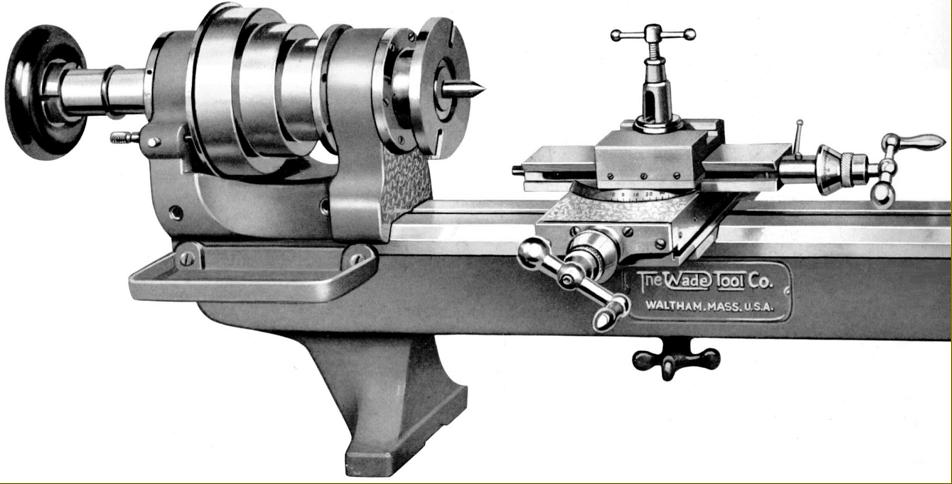
A very early Wade lathe, still with the American Watch Tool Co. logo fitted with a "Top Slide with Changewheels" screwcutting attachment.
This attachment, unlike the "Chase" screwcutting type, could also deal with internal threads. The set of changewheels normally supplied would cut thirty common threads between 30 and 100 TPI; to extend the threading range other changewheels were available to order. Like the rival Waltham lathe, no universal joints were used in the drive - the changewheels of which, when in use, were normally covered by a gear guard.
|
|
|
|
|
|
|
|
|
|
|
 |
|
|
|
|
|
|
Front view of a very early Wade Precision Bench Lathe (still with its American Watch Tool Co. badge) fitted with Chase screwcutting. The first versions of the lathe with this attachment required a special bed with T-slots front and rear.
|
|
|
|
|
|
|
|
|
|
|
|
|
|
|
|
|
|
|