 |
|
|
|
|
|
|
|
|
|
|
|
|
|
|
|
|
|
|
|
|
|
|
|
|
|
|
|
|
|
|
|
|
|
|
|
|
|
|
|
|
|
|
|
|
|
|
|
|
|
|
|
|
|
|
|
|
|
|
|
|
|
|
|
|
|
|
|
|
|
|
|
|
|
|
|
|
|
|
|
|
|
|
|
|
|
|
|
|
|
|
|
|
|
|
|
|
|
|
|
|
|
|
|
|
|
|
|
|
|
|
|
 |
|
|
|
|
 |
|
|
|
|
|
|
|
UK-market badge from the Elliott era
|
|
|
|
|
|
|
American-market badge. Other badges here
|
|
|
|
|
|
|
|
|
|
|
|
|
Made by Maier & Company in Austria and introduced in late 1953, the 1.42" centre height by 5" (later 6.75") between centres Emco "Unimat" was the first of the firm's incredibly popular range of small, multi-purpose machine tools. Although tiny, it was perfectly capable of decent work, available with a wide range of accessories and was light enough to be lifted on and off the workbench with one (strong) hand. The original model stayed in production until 1977, with a run of around 300,000 examples, at which point it was replaced by the Unimat 3, an entirely conventional-looking lathe and one not nearly as adaptable to so many different uses.
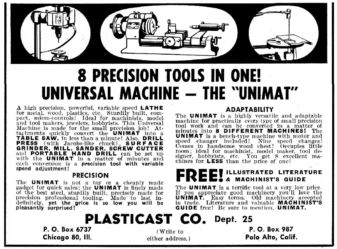
Eventually to be distributed world-wide - with importers using a variety of badges on the headstock - the first known advertisement for what was to become known as the DB200 in the USA, and SL1000 in Europe, has been traced to page 60 in the October, 1954 issue of Model Railroader Magazine and placed by the original American importer Plasticast of Chicago, Illinois and Palo Alto, California. The crude pictures accompanying the text showed not the very first model, but the slightly modified Mk. 1a - now believed to have been the first true production version. It may be that an earlier model was advertised in 1953 - but a search by the writer's German contacts through hobby literature of that year has drawn a blank. However, with post-WW2 production difficulties and material shortages still hampering all industries, it's possible that this first type was never publicised at all, but just offered locally in Austria. The earliest discovered European mention of the lathe was in the February 1955 edition of the popular English magazine "Practical Mechanics" - an early German-language of the full catalogue is here. In the UK the lathe was marketed first by J. & H. Smith Ltd. of 16 Harrison street and 6-8 The Headrow, Leeds, who (as sole concessionaires), had 20,000 copies of their first brochure printed in November, 1954, and issued an instruction book, a scanty A5-size publication titled: "First Junior Instructions for using The Emco Unimat Universal Machine Tool". The basic lathe retailed for £27 : 17 : 6d - at the time around three times the average £9 : 5s : 0d weekly wage of a skilled tradesman. If one was wealthily enough to buy an entire outfit - though few in those days of post WW2 austerity were - it came to around £49 , a considerable sum and enough to purchase a Myford ML7. Marketing was then taken over (at an unknown date), first by "Selecta", an established and much larger purveyor of small tools, as the "Selecta Universal Metal Workshop", and then by one of the country's largest machine-tool manufacturers and agents, "Elliott Machine Equipment Ltd." as the "Elliott Universal Machine Tool". Although this model carried a badge with the designation "SL", in recent years some of Elliott's original advertising literature has caused confusion - they unwisely invented a model designation, the "Unimat 9" (nine machine in one) when really they should just have listed it using "Emco Unimat SL".
By 1956, USA distribution was in the hands of the American Edelstall Corporation, their first advertisement appearing in Model Railroader Magazine during September, 1956. Distribution then moved to an organisation called Emco-Lux, almost certainly a tie up between a long-established German-owned European tool distributor and Maier. Finally, with an expanding range of products, and a move into CNC machine tools, Maier grasped the nettle and brought the marketing and distribution in-house. This situation was mirrored in the UK, where Maier undertook UK sales through a specially-established subsidiary, EME Equipment Ltd. However, as might be expected with such a popular little lathe, Sears Roebuck and Co. in the USA (and Simpson-Sears Ltd. in Canada) were also involved and used their buying power to obtain supplies sold under one of their usual snappy and memorable model designations: 736.21410.
Rather late in the day, on August 1, 1955, a United States patent (No. 2,821,009) was applied for. However, there are four known copies of the Unimat: the Rowic HM-175 from Argentine (possibly still available even in 2021), one of an unknown name manufactured in Russia and the other (possibly) in East Germany. While the Rowic appears to have been so well made - and so similar to the original - that it may well have been manufactured using replicas of the proper factory dies, the other two, from countries under communist control at the time, were significantly different. Two especially interesting home-made Unimats have also been found: the No.1 copy here and the No.2 copy here
Continued below:
|
|
|
|
|
|
|
|
 |
|
|
|
|
|
|
|
|
|
Black crackle finished Emco Unimat Mk. 1 (possibly a Mk. 1a) with its base in cast iron
|
|
|
|
|
|
|
|
|
|
 |
|
|
|
|
|
|
|
|
Believed to be the first American advertisement for what was to become known as the DB200 in the USA, and SL1000 in Europe - traced to page 60 in the October 1954 issue of Model Railroader Magazine and was placed by the original American importer Plasticast of Chicago, Illinois and Palo Alto, California. The crude pictures accompanying the text showed not the very first model, but the slightly modified Mk. 1a - now believed to have been the first true production version. It may be that an earlier model was advertised in 1953 - but a search by the writer's German contacts through hobby literature of that year has drawn a blank - hence this is likely to have been not just the first American, but the first ever advertisement for the Unimat
|
|
|
|
|
|
|
|
|
|
|
|
|
|
|
|
|
Continued:
Although an almost continuous series of small and larger changes altered many details of the lathe's construction and appearance, the general arrangement of all models was identical: a pair of bed bars was carried between supports formed at each end of a "bed tray" that was made first of cast iron, then a heavy zinc "ZAMAK" alloy and, finally, a much lighter grade of ZAMAK. To discover which model you have found, invert the machine and look at the underside of the bed: a single large "X-shaped" stiffening web denotes cast iron, while multiple X-shaped webs indicate a bed in ZAMAK. To distinguish between the lighter and heaver ZAMAK versions (unless you have both together and can pick them up), examine the area where the milling post comes through - on the lighter version there are six bracing ribs around the hole and on the heavier just one round boss, in the middle of a rib, towards the front; on a light base five of the six ribs have round bosses while the 6th, towards the tailstock, does not. The heavier base, having a much higher zinc content (hence the weight), meant that it could be subjected to "plastic cold flow" if left under constant stress. Owners have seen this phenomena exhibited in a Unimat left in the vertical mode for many years where the hole in the base was so deformed that the column was no longer truly vertical. Could the change to the lighter, higher-aluminium content base have been due to this or, much more likely, cost savings?
A central leadscrew was used to drive the carriage up and down the bed rails. Although at first the carriage had no form of lock, later models were given a clamp bolt at the rear that also acted as a form of adjustment to the sliding fit. The cross slide followed the same design and, just like the English Drummond Little Goliath of 25 years earlier, ran on two bars instead of conventional machined ways. The headstock could be swivelled on its mounting and, fastened to its end face (and so rotating with it), was an aluminium bracket that carried the motor and (on most versions) an additional speed-reduction pulley. By reversing the pulleys, and rearranging the belt runs, 11 speeds of approximately 900 to 7200 r.p.m. could be obtained.
With its unique headstock design, ingenious drive system and clever accessory mountings, everything points to the lathe being designed from the outset as a multi-purpose machine that could be gradually equipped with a range of profitable extras. The aim had been to allow its use as a metal or wood lathe, miller, drill press, polisher, grinder, jig saw, saw bench, wood planer or jointer, sander or even - with the headstock detached from the bed and fitted with a grip - as a hand drill. The conversion process from one mode to another was generally well thought out - and simple to execute: for example, to complete the important alteration from turning to milling and drilling, the headstock, complete with its motor-drive system, was removed from the bed and remounted on an aluminium bracket carried on a 24.5-mm diameter steel bar that plugged into the hole formerly occupied by the headstock's mounting stud. As a note of interest there were at least two designs of vertical column and methods of locking them in place: the later type had a groove machined around the shaft with a blind hole, bevelled at its entrance, against which the locking bolt pushed. On earlier examples the hole was drilled though the shaft and a different type of locking bolt used.
In order to provide a vertical feed, the 12 mm threaded headstock spindle and its bearings were mounted within a cylindrical "cartridge", with a rack, formed along its rear surface, engaged by a splined bar inserted into a hole bored through the top face of the headstock. By this means the cartridge, under the tension of a large spring, could be propelled in and out of the casting by 5/8" or so - a movement that was also employed to help accommodate various accessories when in the ordinary lathe mode. The first kind splined drive-bar used to move the cartridge was fitted with a very short, plain handle but later a black knob was added and finally the handle (retaining the ball), was lengthened. To excite the anoraks amongst us, some six variations on the handle have so far come to light. Although the exterior dimensions of the cartridge were one of the few things to remain unchanged throughout production, its contents did not. The first example used a crude system, similar to that employed in a bicycle hub, with crowded (loose) balls contained between cones with the single-groove drive pulley held in place (overhung, at the left-hand end of the cartridge) by an M12-1 nut, the adjustment of which was used to set the bearing pre-load. The outside face of the front cone was ground to an abutment flange for items screwed onto the spindle nose - although this arrangement may have caused problems with the bearing adjustment, with heavier interrupted cuts tending to tighten the cone and reduce clearances. Later arrangements were more sensible and robust, with the use of two single-row, self-adjusting sealed-for-life ball races (NSK Bearings part number E13-305) with wavy "Belville" washers providing the thrust. An alternative precision cartridge, the "Clockmaker's Sleeve Order No. 1022" was also eventually offered; this was designed to appeal to workers dealing with very small components, and accepted tiny B8 collets. The spindle had two bearings at the front - that in 2024 can still be bought - and at the rear a German-made high-precision needle roller race by INA, a Type IA-RNA4903-C2 - the "C2" indicating a close-tolerance unit. The INA are now part of the Schaeffler Group and the bearing should be listed in their online catalogue. The original specification for the bearing stated that the clearance of a standard CO type was 20-45µm but the precision C2 0 to 25µm.
As a point of interest, the spindle from this unit was also used in the Toolpost Grinder (part number VS2-460) that Emco offered for their larger V7, V8 and V10 lathes.
In order to form a chronological sequence, and so help owners categorise their lathe, the various changes to the cast-iron models (in so far as they have been discovered) will be listed as "Mk. Numbers". It must be emphasised that the manufacturer did not use these, nor were the alterations given any publicity at the time. It is also possible that the lathes inspected may have been upgraded or modified - and it is entirely possible that some of the following conclusions are incorrect.
Unimat Mk. 1a: the first production machines are very rare, and this model is the earliest known example on which research can be based. Despite being intended as a mass-production unit evidence from these specimens shows that, at first (no doubt because of the still-severe economic conditions at the time), the Emco factory would have had a limited number of automatic production machines and a good deal of hand-work went into each example. There is also an indication that little time or material was wasted with, for example, the castings having an indifferent cosmetic finish and wrongly spotted and partially-bored centres holes corrected - but with the initial damage to the component ignored. As it would have provided the easiest and most reliable route into production the first version (like nearly ever other amateur lathe of the time), had its base and other major castings in iron. The first lathe, with an overall length 16-inches, was shorter than later versions and the base unit just 123/8-inches from end to end that allowed a capacity of only 5 inches between centres. Unique to the first one or two years of production the base's other main identifying features were its middle section, formed into a convex chip tray (with a flattish bottom), raised ridges running along the front and back walls and the boring of the casting at both ends to accept two solid-steel, 12-mm diameter bed bars each retained by a horizontal grub-screw. That section of the base on which the headstock fitted was rectangular in shape, with a flat front, and bored to accept a large "inverted-cone" that allowed the headstock to be rotated or quickly detached. A pin, screwed in through the left-hand face of the casting, engaged against the cone, and drew the headstock down and locked it in place. Unfortunately there was no provision for aligning the headstock, other than fitting the tailstock ram with a centre and pushing it into the spindle hole - while simultaneously tightening the locking screw.
There were several serious oversights on this first model including a lack of provision to lock either the saddle or the cross slide to their respective bars and feed-screws with a 'right-hand" thread' - giving that annoyingly counterintuitive situation where turning a handle to the right produced a moment towards, instead of away from, the operator. One feature found on some early models (the writer's own example being so equipped) was a tiny oil hole drilled vertically through the front wall of the carriage by which means the end of the cross-feed screw, where it passed through the casting, could be lubricated. The smaller turned-parts on were probably made on a "Swiss Auto" - and ideal machine for making quantities of precision miniature components - with the plain-steel, 28-mm diameter handwheels having a pleasing diamond knurl around their outer edge, tiny micrometer dials engraved into the inner boss and straight pins for hand-grips. It is likely that more than one kind of handwheel was fitted on the production line, with some being of a slightly different diameter to others.
In comparison with later machines the drive pulleys exhibited several significant differences: they were thinner in section and of a much lighter, even delicate construction. Manufactured in fully-machined cast aluminium they had deep 'V' grooves and were mounted in the reverse direction and with the pair used on the motor and idler stud (at 49-mm), larger in diameter. The original belts were in the form of coiled-steel wire "springs", not an ideal material to run against aluminium. The motor bracket, later a neat die-cast affair, was a rather rough aluminium casting with only the holes machined. From the start of production the motor bracket came with an idler pulley - but machines have been found without this fitting (possibly to ease the fitting of a particular accessory) and hence only 6 instead of 11 speeds. A later offering was a "slow-speed" bracket with two idler pulleys designed to allow much lower revolution and so make more effective use of the "chase-type" screwcutting attachment.
Constructed as a one piece casting, the first tailstock had a distinctive spindle-retaining nut, just inboard of the handwheel, and a very pronounced rearward cantilever (to maximize the machine's limited between-centres' capacity). Because of its construction, and the fact that the bed bars were socketed into the base casting, it was necessary to dismantle the entire lathe if the tailstock had to be removed.
Instead of a taper, the 3/4-inch travel ram was fitted with a parallel socket and a external thread identical to that used on the headstock. An examination of the castings used on early lathes show them to have an inferior finish to later ones, though no doubt their material quality was entirely satisfactory. The vertical pillar was 24.5 mm in diameter, 240 mm long and with an installed length of 200 mm. The hand-grip used to convert the headstock into a drill was quite rounded, perhaps a little smaller than the latter cast-iron production version--but much more comfortable to use.
Made in Holland (by Motoren Eindhoven) the ball-bearing, 40 watts, 4000 r.p.m. brush motor resembled those used on contemporary sewing machines and was rated for intermittent use only. In order (no doubt) to give the unit a "machine-tool" or "technical" appearance it was finished, apart from the black-varnished field-lamination area, in an attractive crackle-black paint to match the lathe. To check if a motor has plain bearings look for a small hole in the (protruding) bearing housing at each end. The hole leads to a felt washer that wicks just oil, less any dirt, into the sintered-bronze bearings.
American machines all appear to have been delivered in a rather splendid fitted wooden box - while European customers, apart from those sold during the mid to late 1950s, had to be content with finest-quality cardboard. If you see a box for sale be aware that those for the very first models - the Mk. 1a at just over 12-inches long - were smaller than those for later machines. Most of the first boxes had nicely bevelled vertical corners, until at some point during SL1000 production , this was stopped, probably as an economy measure. Accessory boxes of the time were very distinctive with a turquoise (or teal) blue-and-white label with "Emco" spelled out in a diagonal line, a 'circle M' logo and "Made in Austria" printed underneath in small letters.
Having established the lathe in production, Maier set about both improving production methods (which necessitated changes to the machine's construction), and ironing out some of the design deficiencies that were becoming apparent as owners began to explore the limits of its potential.
Continued below:
|
|
|
|
|
|
|
|
|
|
|
|
|
|
|
|
|
|
|
|
|
|
|
|
|
|
 |
|
|
|
|
|
|
The very common Die-cast Unimat SL1000
Continued:
Unimat Mk. 1B: this version retained all the main characteristics (and deficiencies) of the Mk. 1A with the important exception that the bored holes for the way bars were replaced with V-grooves into which the bars sat to be held in place by screws passing vertically though them - as on all subsequent models - so allowing much quicker construction and disassembly. Some examples of this version have also been found with saddle and cross-slide locking screws (the latter with a small brass plug pushed against the right-hand cross-slide bar) but such fittings appear not to have been standard until at least the Mk. 2A. It may well be that some owners, frustrated by the absence of a carriage lock on their early machines, could have fitted their own - so it is impossible to be categorical on this point. The tiny instruction book issued with this model was marked as being the 2nd edition and was originally typed on an A4 sheet, reduced to A5 and bound in grey card.
Unimat Mk. 2 and 2A: the iron base casting, now with a better finish, was lengthened to approximately 141/2 inches giving an increase in the between-centres capacity to 65/8 inches. The tailstock cantilever was reduced and the casting became a two-piece affair with the upper and lower sections clamped to the bed rails by a single Allen bolt. Although the 2 and 2A had a carriage lock (at the back) the cross slide generally did not - that improvement appearing as standard on the 2B. The feed-screws on these models were changed to a left-hand thread, so allowing a "normal" feel - where turning the screw to the right resulted in a deeper cut; a far better arrangement than the "cack-handed" originals that did the opposite. The handwheels, now larger at 35-mm in diameter, were made slightly thinner and given a knurled rim and a locking nut on the end of their feedscrew, instead of through the wheel's boss. Again, with over-lapping production, it possible that these handwheels may have been seen first on the last examples of the previous type.
Arranged by the simple and effective means of splitting the right-hand half of the casting from front to back, the cross-slide clamp used an M6 socket -headed screw set (positioned at the front between feed screw and the right-hand 8 mm-diameter cross slide bar) to squeeze the parts together. However, this was not the first type of lock and some earlier versions have been found with a cruder system where, on the right-hand side front of the casting, an 11-mm wide tapped boss was incorporated that took an M6 x 8 mm grub screw bearing directly onto the way bar. So as not to mark the bar, a small brass button was used on the end of the screw. Although the system worked well enough, it did not have the clamping power of the later type and would probably not have stood up well to the demands of heavier milling cuts. As a further confusion, some early machines of the Mk 2 and 2A type have been found with two locking screws on the cross slide, one at the front and another other at the back.
Improvements were also made to the headstock, with the spindle being given a register flange and the 2-step pulley made reversible on its mounting - so providing an increase in the number of speeds. The 3-jaw chuck and the drill chuck delivered with this lathe were identical to the ones supplied earlier, with the ring-scroll portion of the 3-jaw (the part gripped to turn the scroll) being diamond knurled and drilled with 6 Tommy-bar holes. The entire body of the drill chuck was also given a distinctive (and effective) diamond-knurl finish. It is likely that the Mk. 2 and 2A were delivered in several finishes: the original crackle-black, a silver-grey, plain-grey and late ones possibly in a silver-blue "hammer" effect.
For the American market the 2A Instruction book was published by "American Edelstaal" in New York and was a considerable improvement over the original. Although some of the original illustrations were used, the robin's-egg blue paper and a different font, properly typeset and justified, made all the difference.
Continued below:
|
|
|
|
|
|
|
|
|
|
|
|
|
|
 |
|
|
|
|
|
|
|
|
A Mk. 2B 1950s Unimat with the lovely crackle-black finish: distinguishing features include the bed bars sitting on top of the tailstock-end base casting, the tailstock handwheel located by a grub screw rather than a large nut and the headstock aligned by a simple vertical "key" inserted between upper and lower castings. This example also has a locking screw on the cross slide.
|
|
|
|
|
|
|
|
|
|
|
Continued:
Unimat Mk. 2B: although the major components continued unchanged this version it was the first to incorporate a means of aligning the headstock with the bed bars. Upon first assembly the base casting and headstock were jigged and a small vertical slot cut across the junction of their front faces. When the faces were correctly aligned (by using the tailstock method previously outlined) it was possible to insert into the slot a small "setting piece" - a disc washer given by the handbook as being 0.748" in diameter. However, one measured has been discovered to have an OD 0.734", and ID 0.333" and a thickness of 0.1577". Whilst the OD and ID are plain machined the flats were ground). A photographic essay for the Mk. 2B can be found here
Mk. 2B …. The handbook instructions differed from edition to edition, but the following is probably the clearest given: "...two corresponding grooves have been milled in the bed and the headstock housing. If, with the tension screw (No. 4 Fig. 1) slackened, you insert the accompanying setting piece (no. 55) (disc washer 0.748" in diameter) in the milled grove and tighten the tension screw again, the headstock and tailstock will be lined up. The setting piece may be removed again after the headstock has been clamped in position." Removing the setting piece would, of course, have guaranteed its immediate loss.
The motor was the now-familiar larger plain-bearing Dutch unit, with the centre portion painted ether black or in a colour to match the rest of the machine. Several styles of handwheel were used, all turned from steel and plated silver or black. Towards the end of the Mk. 2B production run it is believed that the first of the new (and cheaper to produce) die-cast handwheels with the delightful "wasp-tail" handles was introduced. Some versions of this lathe have been found with two locking screws on the cross slide, one in the normal position nearer the front and the other in line with it further back. Realising that one 6 mm screw clamping the casting to the slide bar was entirely adequate, Emco did not persist with this modification. Unimats of this age were also given a more robust carriage assembly with the whole of the casting, including the front and back walls through which the way-bars passed, noticeably thickened.
Colours, as ever, pose a problem and instead of a single, standard finish, examples have been found in crackle-black, a light plain (flat) grey and others in either silver-blue or silver grey - with the latter two in a "hammer-effect" paint.
Unimat Mk. 3: the lathe that introduced the third type of base, longer and with a completely new shape with a convex instead of concave centre section - yet with the headstock support end still rectangular in form and an identical design of headstock-alignment washer. It is likely that only two motors were used on this model: the original Dutch-built brush-type and, towards the end of production, a larger induction . Type. By the late 1950s crackle-black finishes were being phased out and Emco followed fashion by producing the majority of the Mk. 3 lathes in a variety of finishes, amongst which silver-blue appears to have been predominant. The "pea-green", pre-1959 Emco brochure shows just such a machine, with the larger Dutch motor: an example of this type is known to have been manufactured in late 1957, and delivered to its first owner in April, 1958.
The Instruction Book for the Mk. 3 is the more common 3rd Edition, composed and typed (probably) in England as an A4 sheet, reduced to A5 and printed in Salzburg, Austria.
Emco Unimat Model W:
At around this time Emco introduced the Model W, a simplified "Woodworking" version bereft of carriage and feed-screw. The only known data for this version appears in an undated (though circa 1960/64) German-language brochure where the machine appears with a "Model W" script in the top left hand corner of the red nameplate with the European "PAT.ENG" marking. The first version of the W appears to have been based on a mid to late Mk. 3 with die cast handwheels, a U90 motor and an "alignment-slot" headstock. It had the long 12 mm Guide Bars (A2Z230010), the long T-bar Tool Rest (DB1201, later DB1202), a wood-drive centre (spur type DB1205) and a single-row ball-bearing rotating centre for the tailstock. (DB1200). The tailstock handwheel was black turned steel with a 'wasp-tail' handle. The same catalogue also shows a unique tool block (DB1320) with two T-slots running front to back and a single clamp screw with a clamp piece. It was sold specifically for use on the 'W' and appears to have been offered in Europe only. It was designed to hold the small triangular tool rest (or other accessories) at the standard cross-slide height. Because it's possible to convert a "W" to the specification of an ordinary metal-turning Unimat (or use the "W" headstock on another machine) it's likely that the model may appear on the used market in a variety on non-factory specifications. Production of the "W" continued into the dies-cast era but, with so few about, only limited numbers can have been sold..
|
|
|
|
|
|
|
|
|
|
|
|
|
|
|
|
|
|
|
|
|
|
Unimat Mk. 4:
Notable for the introduction of a rounded "step" in front of the headstock through which a simple vertical alignment pin could pass, this was the last version of the Unimat to use a cast-iron base. There was also a slight bevelling of the upper corners of the headstock support - an alteration that would be reflected in the forthcoming die-cast design - and the headstock itself may also have been increased in size slightly but with corners of a tighter radius (measurements are awaited) and its milling post-retaining pin moved to a position parallel to the spindle cartridge.
Motors used on this model included the Dutch-made painted type (the large "round" version), an early example of the very much stronger and reliable U90 (but with more sculptured end caps as shown in the large picture in the 1959 brochure) and the "regular" U90 in a colour to match the lathe. However, it is known that silver-blue finished U90 motors were subsequently sold by American Edelstaal, and Canadian Edelstaal, as replacements for use on later green SL1000s and DB200s and so confusion on this point is a strong possibility.
Early Mk. 4 lathes had blackened steel handwheels with wasp-tail handles, a red nameplate, the Dutch 95-Watt motor and a silver-blue hammer-finish paint. Versions made in the middle years of production can be recognised by the use of die-cast handwheels (still with wasp-tail handles) and a red-silver-red badge. The last Mk. 4 can be identified by a larger, black-finish nameplate carrying the word Unimat (but no model designation) with handwheels changed yet again, this time to a turned-aluminium type with "single-line" knurling around their edges, this finish also bing used on the next model to appear, the SL. The motor was a U90 type and the finish either a pale grey-green hammer effect, or plain grey. However, there was a degree of overlap between the machines, with even early-production examples found (though only rarely) with the early red nameplate, U90 motors and aluminium handwheels. The Mk. 4 was finished in a hammer-effect, pale grey-green and supplied with the lathe were two accessories that would become very familiar in years to come: a rather light faceplate and drive dog - both in die-cast aluminium. A recent discovery was a Mk. 4 purchased, according to its original owner, in 1960. This had a big, round-shaped induction motor with matching wrapper paint, a small red name plate mounted low down on the sloping face of the headstock, green paint and die-cast hand wheels with the wasp-tail handles.
Unimat SL1000/DB200 Die-cast Models
At some point during the early 1960s (evidence points to 1964), the factory went over from an iron base to one formed from a pressure die-casting in a heavy-duty grade of ZAMAK or a similar material. These new models were on sale in England by early 1965 and the USA a little later, in April 1965. However, it is more than likely that stocks of the older cast-iron machines had not been exhausted and the two models may have been available side by side for some time. The change of material enabled the rate of production to be greatly increased and, by eliminating some machining operations (the finish of the castings was equal to a ground surface) costs reduced. The use of dies enabled the appearance of the base to be cleaned up somewhat and allowed an almost full-length, vertical flat face to be used. These first die-cast machines have become known as the "Heavy" Unimat because, a little later, yet another change of material was made to a different grade of ZAMAK resulting in the "Light" version. On the "Heavy" models at the point where the M6 screws retained the bed rails (at both headstock and tailstock) the casting was given two parallel grooves. The "Light" models were painted a hammer-effect green and with minor mechanical alterations only, including rather crude, cast-in degree-graduation marks on the front of the headstock. In America the very last production machines were distributed by LUX (replacing American/Canadien Edelstaal) and can be identified by a large red name plate, a U7750 motor and rather horrid plastic handwheels (similar to those on the Unimat 3) - but with clear, white-painted graduations that are preferred by some owners. Unfortunately, this model was not well finished and lacked the delightful detailing of earlier machines: it had, for example, a number of surfaces that lacked accuracy and a headstock spindle sleeve with a turned rather than a ground-finish.
Motors:
In the 1950s and 1960s very few European countries used the same voltage for their domestic supplies and Emco had to supply a wide range of motors to cover every possibility - new examples of which are still being discovered. As an example of the confusion that reigned an original, unused lathe from 1961 has been found fitted with 125 watt 2800 rpm motor but accompanied by a 3rd edition Operator's Manual stating that a 65 Watt, 4000 rpm unit was fitted. (Machine Serial No. 260031 sold in 1961 for the Dutch market). Apart from the very first examples, American-market machines were fitted with motors of a different design and size to those in Europe (and possibly the rest of the world). The specification plate of a typical US-market DB200 usually read: 95 watts, 3500 RPM, 115 volts, 50/60 cycles, 0.9 A. However, by the mid 1960s the technical literature with USA-market machines was showing two motors: a brush type 16,000 rpm (no-load) and an induction type 3,600 r.p.m. (no-load) unit. Failure of Unimat motors is very common and the causes manifold. However, before fitting a remotely mounted sewing-machine motor as a replacement it is worthwhile dismantling the faulty unit and checking to see if the delta capacitor (for commutator suppression) buried inside the motor casing behind the rear of the armature, is faulty. This unit contains three small capacitors within the single casing and it is not unknown for one to have short circuited to earth internally. If a physically similar replacement capacitor cannot be found an electrically compatible one - in the UK for example a Maplin Electronics Part No. PZB 300 (delta cap, 0.1uF+2×4.7nF 275V) is known to work. If necessary this can be mounted in an external box on the rear of the motor with a new on/off toggle switch on top.
Motors were fitted with either plain bronze or ball bearings with, in general, those for Europe with voltages above 200, using ball races and most American-market U90s with plain bearings - though an exception was the first 40 Watt motor that used ball-races. The plain bearings were lubricated through wicks, and it's important not to take these out and squirt oil in directly - doing so will wreck the motor. If the felts have dried out remove them and soak in thin oil for a couple of days - that usually gets them working again; alternatively, fashion new felts from material easily available from dress-making shops. The ball races are grease lubricated - using oil will wash the grease out and foul up the inside of the motor, again promoting failure. If the motor is stripped, just a trace of grease on the bearings is sufficient - and, whilst it's down, check to see if the bearings are loose in their housings; if they are, secure them with a low-strength grade of Loctite. If you are unsure which bearings your motor has, examine the end of the shaft, it's sometimes possible to see the bronze ring of the plain-bearing type.
Collets
The early EMCO Maier supplied collet holders were for the E-16 and ES-6 series of collets from Schaublin in Switzerland and were a little shorter than the ER-16 style (introduced in 1972 by Rego-Fix, also of Switzerland, in 1972) ES = Schaublin, ER = Rego-Fix. The E collets have just 6 slots and, as with a collapse range of only a few thousandths of an inch, are intended for use only with the "nominal" size marked on the collet. The ES and ER collets have 8, 12 (or more) slots and a collapse range of about .040". ER collets also have an extraction groove-- the E and ES collets do not. The diameter of the E and ES collets is measured at the largest diameter where the two cones meet which, in the case of E/ES-16 collets, is 16 mm. The ER type are measured at a defined distance below the extraction groove on the 8-degree (16 Degrees included angle).
An ER-16 collet can sometimes be used in an E/EX-16 holder - but never the reverse i.e. an E/ES-16 collet in a ER-16 holder - if this is tried the extractor in the nut will ruin the smaller collet. Although the ER-16 collets will seat in the E/ES holder they will protrude more and the nut may not have enough threads to engage the body safely. Schaublin now makes an ESX-16 collet set that is compliant with the DIN standard.
The E/ES-16 series became obsolete in mid 1980s..
Although the DB200/SL1000 remains a very popular machine on the second-hand market Emco unfortunately no longer supply any parts, accessories, written material or service help.
How long-lived and reliable is a Unimat? In April 2006 the writer met a model engineer who had been given one as a present for his 21st birthday some 40 years previously. Although it had been in regular use, it still retained its first motor (he had been careful not to exceed the time-limited running) and even one drive belt was original. Nothing had broken or worn out and he was entirely delighted with it. Of course, collectors have moved into the market and very early black-finish machines - and most of the accessories from any year - are very sought after and command high prices..
|
|
|
|
|
|
|
|
|
|
|
|
|
|
|
|
|
|
|
|
|
|
|
 |
|
|
|
|
|
|
The earliest known sectional drawing of the headstock, dated 1954
|
|
|
|
|
|
|
|
 |
|
|
|
|
|
|
|
|
|
|
|
|
|
|
Mk. 4: Late 1950s headstock with the vertical, hexagon-headed alignment pin
|
|
|
|
|
|
|
|
 |
|
|
|
|
|
|
Mk. 4: Late 1950s carriage with a single locking screw on the cross slide, wasp-tail handles and crude, cast-in degree marking on the feed-screw handwheels.
|
|
|
|
|
|
|
|
 |
|
|
|
|
|
|
Mk. 4: Late 1950s tailstock and leadscrew handwheel assembly
|
|
|
|
|
|
|
|
|
|
|
|
|
|
|
|