|
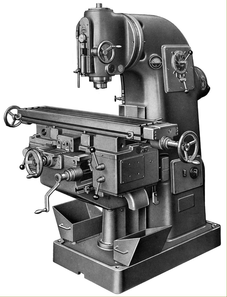
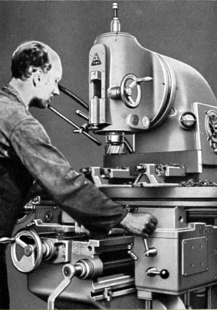
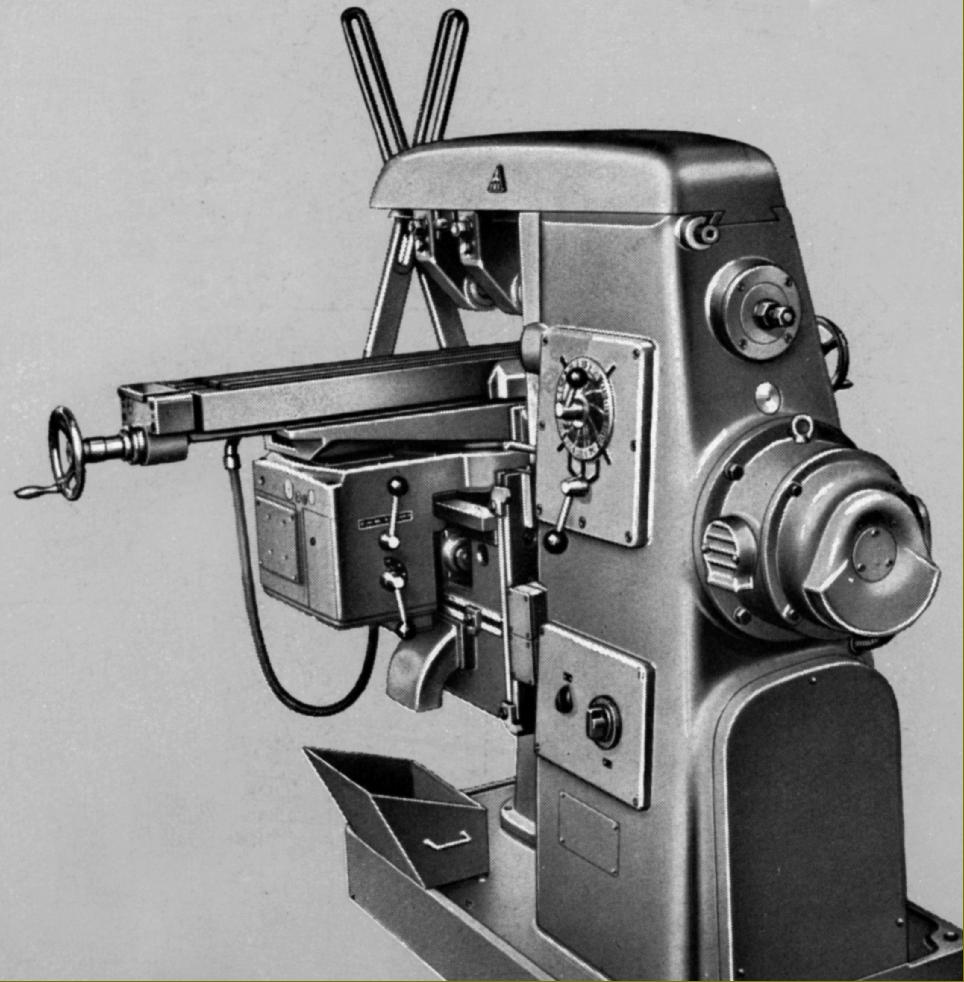
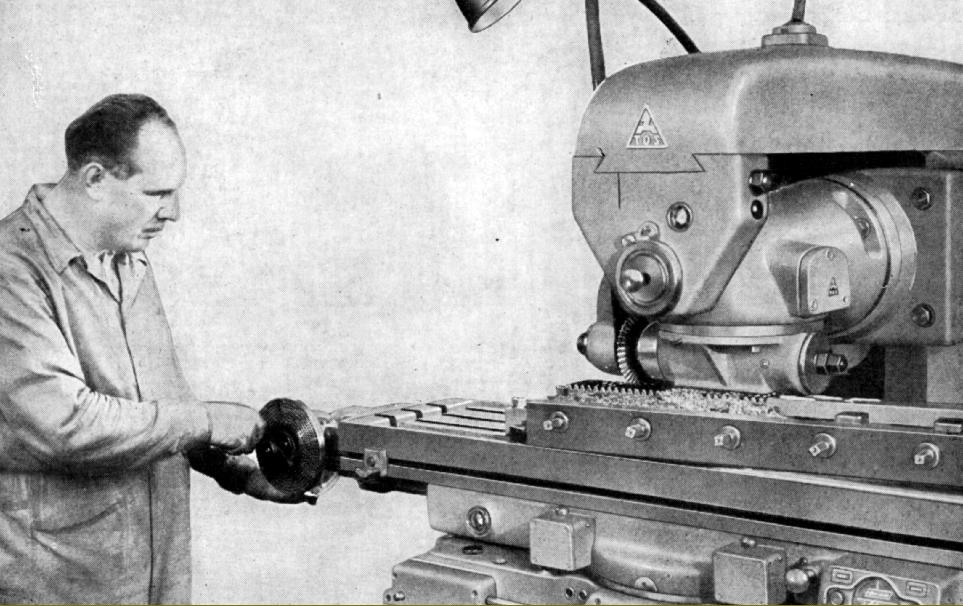
TOS Zbrojovka FA3-V Vertical
Continued:
FA3
Next to smallest in the range, the FA3V, FA3H and FA3U all had a table 250 mm wide by 1250 mm long with three 14 mm T-slots on a 55 mm spacing and both power and "rapid" feeds longitudinally and - in contrast to the FA2 - also in traverse and vertically, all movements being powered by a separate 740 kW (1 h.p.) 1380 r.p.m. motor. Flange mounted against the rear of the feed gearbox, fitted at the left-hand side of the saddle, drive from the motor was initially through a pair of bevel gears and then via multi-plate clutches with overload protection with a single, spring-loaded directional lever on each axis providing the control. Travel stops were not mechanical but electrical, their activation stopping the motor.
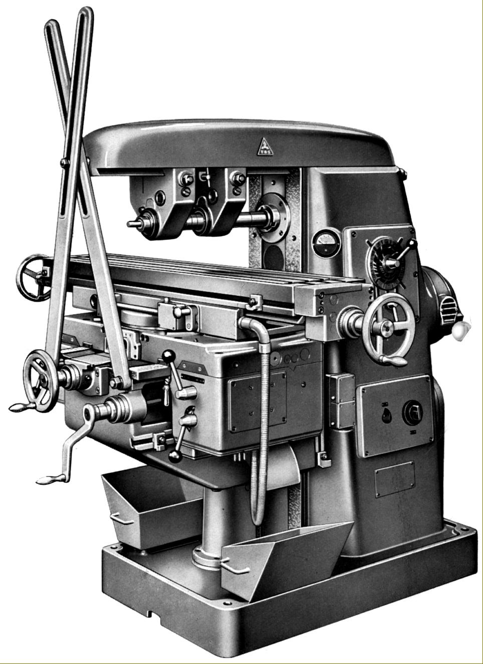
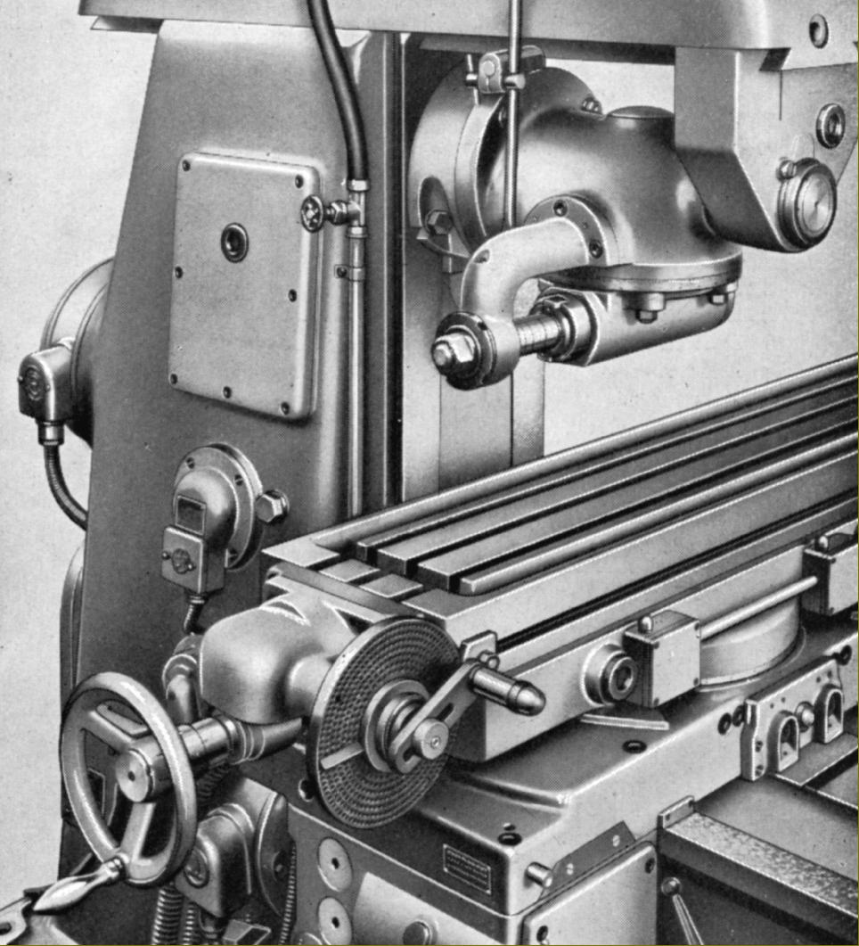
Longitudinal travel was 810 mm by hand and 800 under power and, respectively, across 280 and 270 mm and vertically 410 and 400 mm. Thirteen rates of power feed were available, these ranging from 14 to 900 mm/min both longitudinally and across - the full range being: 14, 20, 28, 40, 56, 80, 112, 160, 224, 315, 450, 630 and 900. Vertical rates were set at 25% of the others, being from 4 to 250 mm/min. Rapid traverses were set at 2800 mm/min longitudinally and across and at 800 mm/min vertically. Table power-feed controls - selection of direction, engagement and rate were all duplicated at the rear of the saddle at its right-hand end, so allowing the machine to be operated from the rear of the table - a possible bonus on some long or awkwardly-shaped jobs.
Positive lubrication of the feed speed-change gearbox was by a piston pump, the recirculating supply also able to be directed (unfortunately not automatically but by pressing a handle), to send oil to the table feed screws and their support bearings and the sliding surfaces of table, saddle and knee - though the column surfaces of the latter, and the bearings of the table's longitudinal feed screw, were lubricated through grease nipples. The heavily loaded knee screw was lubricated by an oil bath and, copying established Cincinnati practice, when normal or rapid feeds were engaged by a circulating supply.
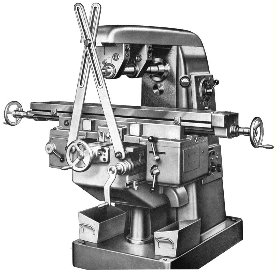
Both horizontal and vertical spindles were mounted on their noses in a precision-grade, double-row roller bearing with a tapered bore that allowed a very precise adjustment to be made of the running clearance. Spindle nose fittings listed as being available included an ISA 44, metric 32 and No. 4 Morse - though doubtless others would have been supplied to special order.
Able to be swivelled 45° each side of upright, the vertical head had a quill with a fine-feed travel of 75 mm with, instead of a screw-type adjustable depth stop, a telescopic design that was also connected to a dial indicator. In addition, for very precise work, it was possible to fit slip gauges into the stop mechanism.
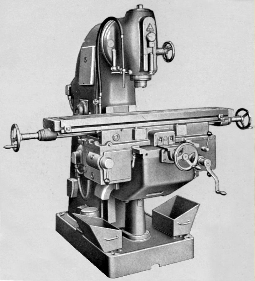
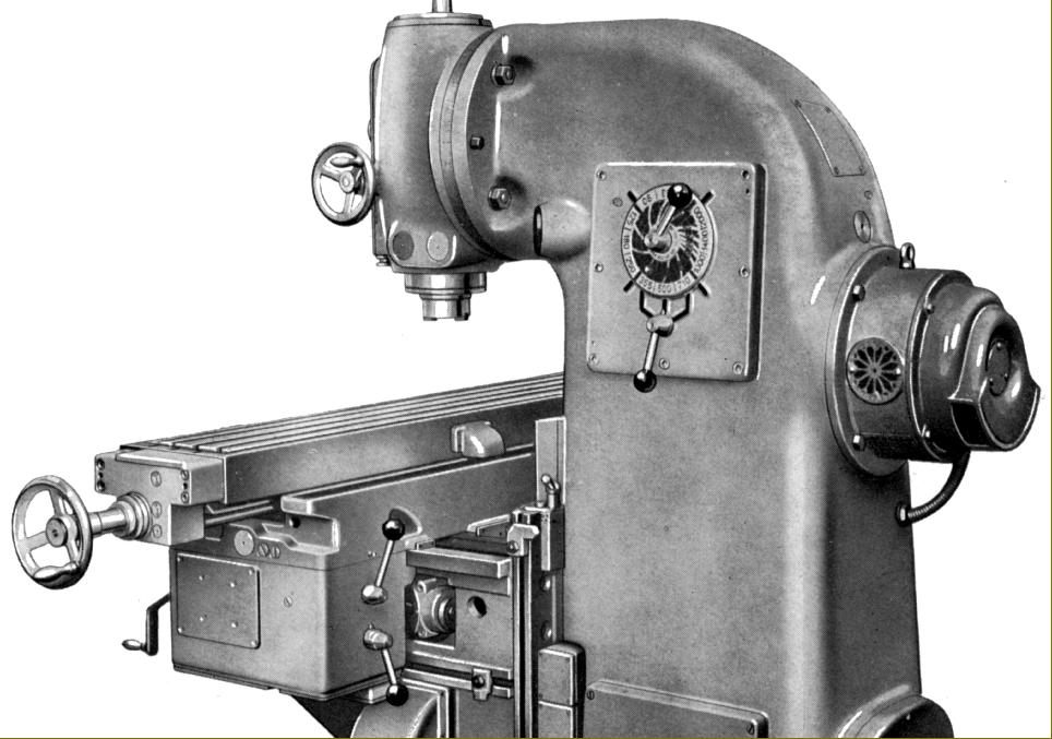
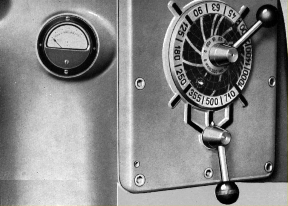
Drive to both vertical and horizontal spindles came from a low-profile, 1430 r.p.m. 5.7 h.p. motor flange mounted against the rear of the main column with control by a forward-reversing switch and "Start-Stop" push buttons - with that for "stop", when held down, bringing in an electrically applied braking effect created by a rectifier supplying direct current to the motor - the system being listed by the makers as being of the "Alnico" type. Motor overload protection was by thermal relays and the operator provided with an Ammeter to gauge how hard the machine was working.
Twelve spindle speeds were available, these being generated by a gearbox held within the main column and operated by two levers: one rotary the other quadrant. The speed range was identical for all three models: 45 to 2000 r.p.m. as standard but with the option of higher range that spanned 63 to 2800 r.p.m. Lubrication of the speed-change gearbox, spindle bearings and bevel drive to the vertical head was by an electrically driven gear pump.
Coolant was held in the hollow foot of the miller and supplied by an electrically-driven pump. Returning coolant and chips were drained from the table and saddle through broad channels in the knee and then into detachable pans at either side (these holding coarse separator screens), before returning to the base where the compartment was divided into a number of settling tanks.
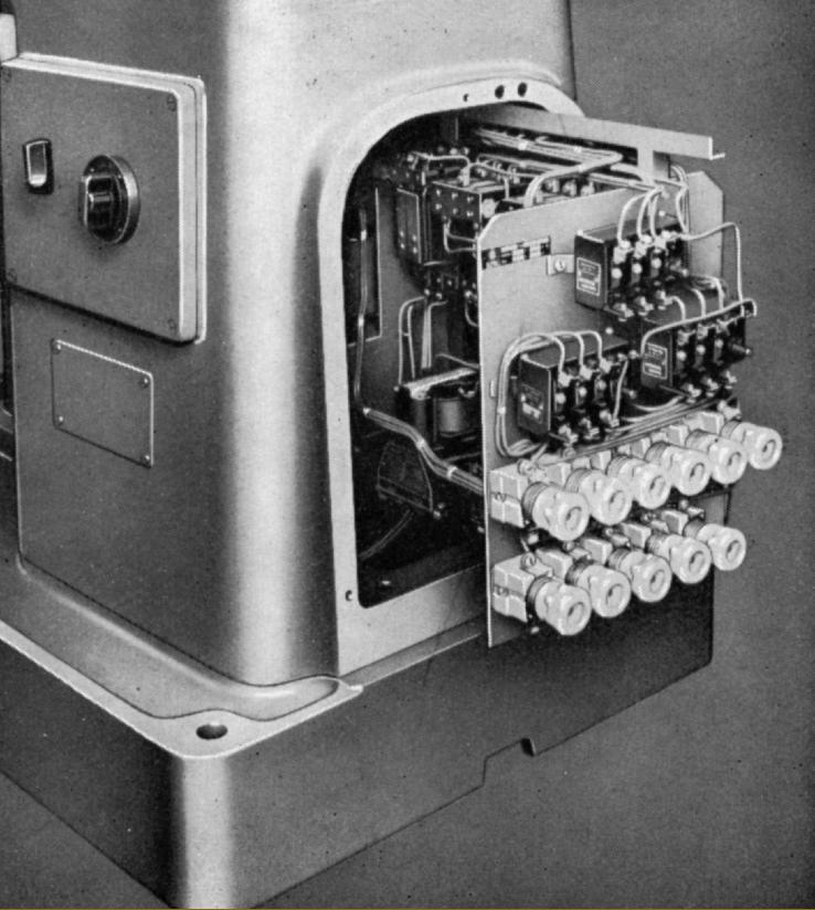
Electrical contactors, fuses and associated hardware were grouped together in a compartment at the back of the machine, the whole assembly being mounted on a neat, slide-out tray.
Supplied as part of the standard equipment with each new machine were the following: a milling arbor, coolant equipment, a complete electrical installation to the customer's voltage requirements, a grease gun, a set of spanners and an instruction book.
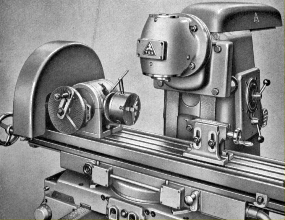
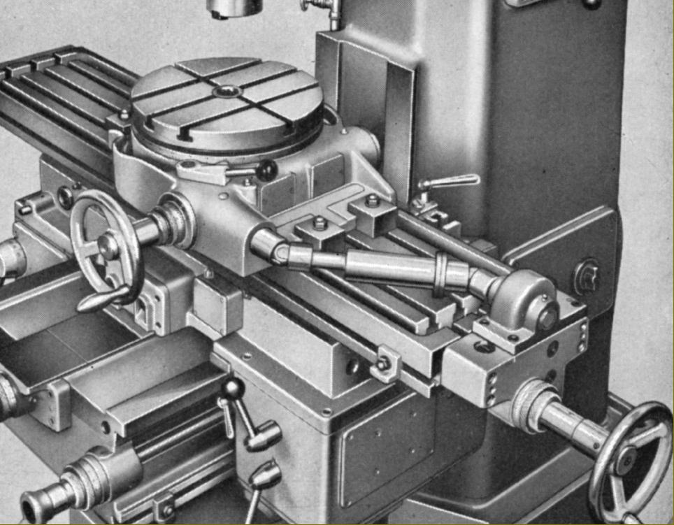
A number of useful extras was offered including a power-driven universal dividing head with tailstock and a support for long work, a power-driven rotary table and, for the horizontal models, standard, universal and circular vertical attachments, a rack milling device and a circular attachment with hand drive. In addition the usual range of machine vices, different diameters and lengths of milling arbor, spindle-nose reducing sleeves and collet chucks, etc..
|
|