 |
|
|
|
|
|
|
|
|
|
|
|
|
|
|
|
|
|
|
|
|
|
|
|
|
|
|
|
|
|
|
|
|
|
|
|
|
|
|
|
|
|
|
|
|
|
|
|
|
|
|
|
|
|
|
|
|
|
|
|
|
|
|
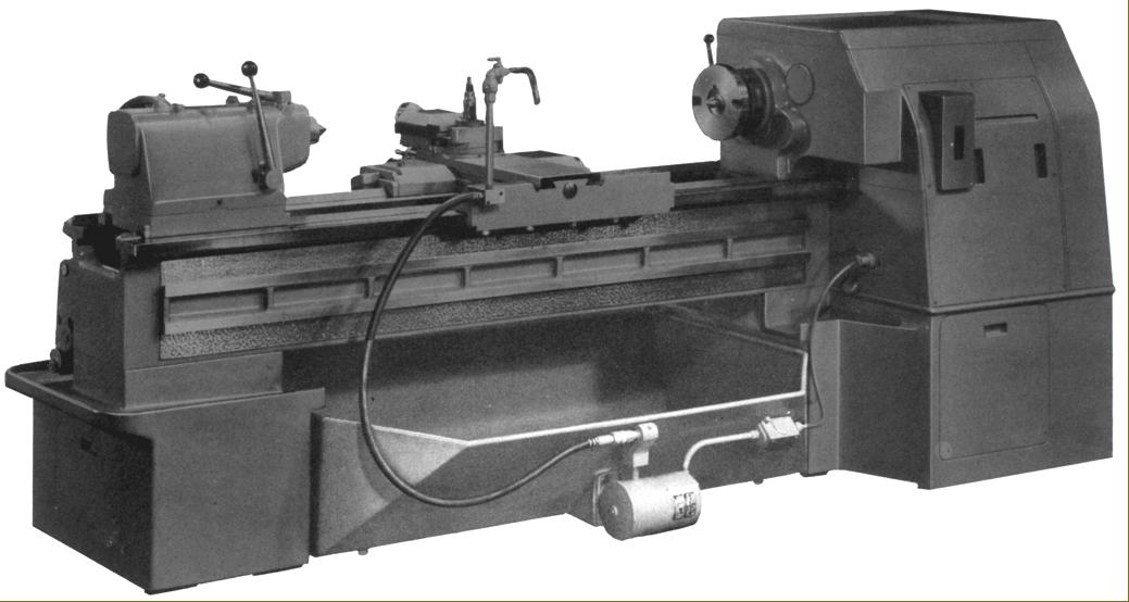
One of the earliest makers of machine tools in the United States, the Springfield Company produced lathes that were always of the heavy industrial type, intended for serious production or one-off work with nothing lighter or cheaper offered for the repair shop, garage or amateur market. During the early 1950s the range included both survivors from an earlier age, such as the robust and heavy Model 180, and two very up-to-date types, the Model S and Model 280. With clean, angular lines the latter pair made all earlier versions look distinctly old-fashioned, yet still incorporated numerous tried and tested features including a particularly wide speed range, a clutched drive for power sliding and surfacing feeds, a most useful automatic disengage of screwcutting and longitudinal power feeds and oil pumped under pressure, from a base container to the headstock internals. Although the various models had overlapping specifications and some sharing of parts, each was built to fulfil a specific role as either a medium-duty, heavy-duty or toolroom machine.
Springfield Model S
Available in two sizes - 16" x 30" "heavy duty" and 20" x 54" "medium duty", both Model S lathes were of identical appearance and shared the same mechanical specification - though of course their centre height, distance between centres and mass differed - the smaller type weighing 8165 lbs and the heavier 8865 lbs. Both had more swing than their Model designation suggested: 18.5" for the smaller and 22.5" for the larger, but shared the same deep and well-braced straight bed, a wide range of 24 spindle speeds, 60 threads and feeds from the screwcutting gearbox and identical compound slide rest assemblies, aprons and saddles, etc. While the 16-inch was intended for hard work within its capacity range, the 20-inch had the centre height increased to handle bigger jobs, but these, when larger than those able to be turned the 16-inch, had to be handled with a degree of care and a limited depth of cut.
Bed and stand
Massively built, the straight bed was cross-braced by webs in the form of equilateral triangles and was without a (weakening) gap. V and flat ways were used, constructed in strips of hardened steel inserts they were, according to the makers, replaceable when worn. Carrying the bed were two suitably large and heavy cast-iron plinths with that under the headstock holding the motor - drive to the headstock input pulley being by five V-belts. Between the plinths was a large chip tray with, bolted to its rear face, the coolant motor and pump. Running on ball castors, the tray could be slid out for cleaning with snap-connectors used to join the pipes and electrical wiring.
Continued below:
|
|
|
|
|
|
|
 |
|
|
|
|
|
|
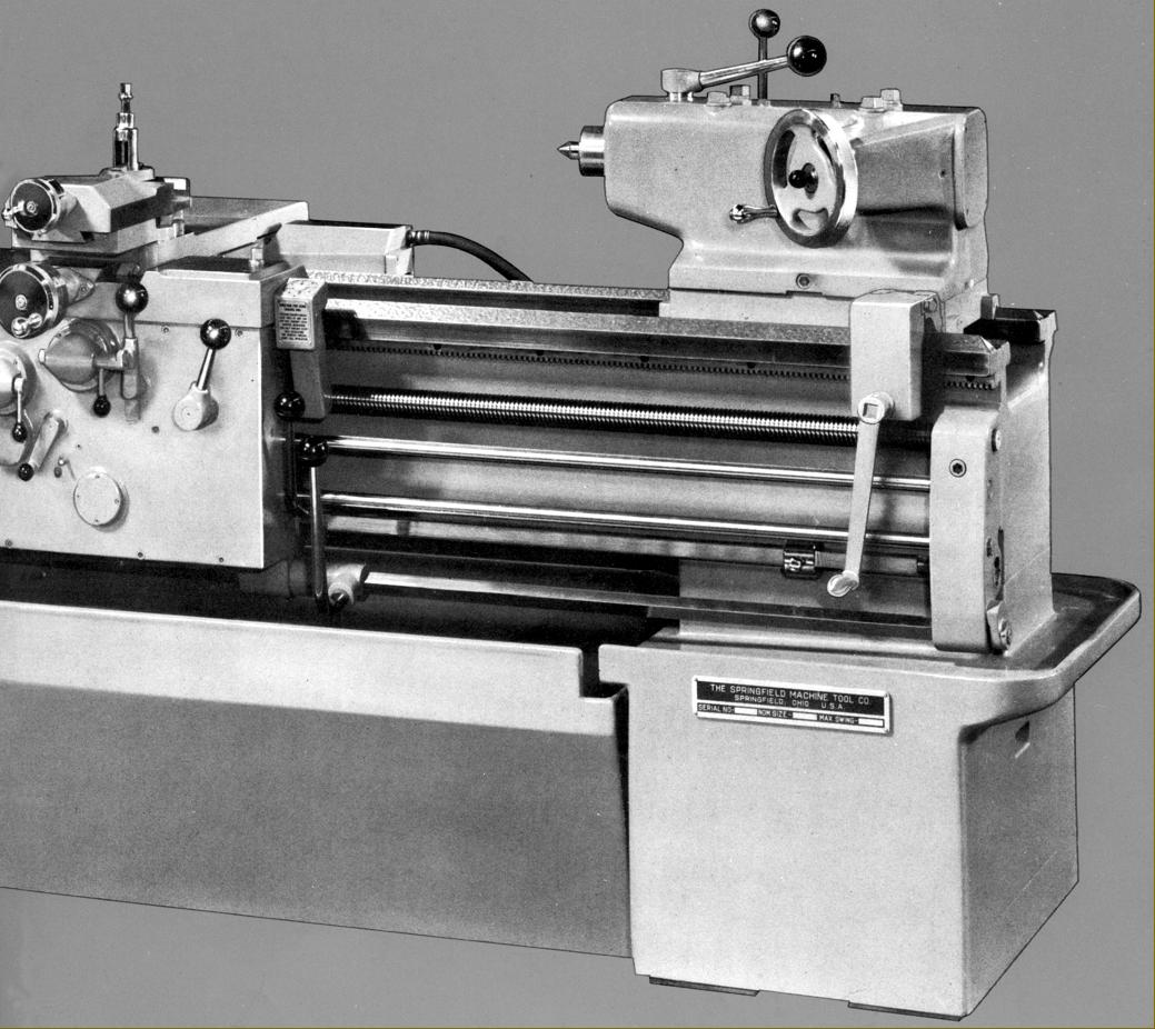
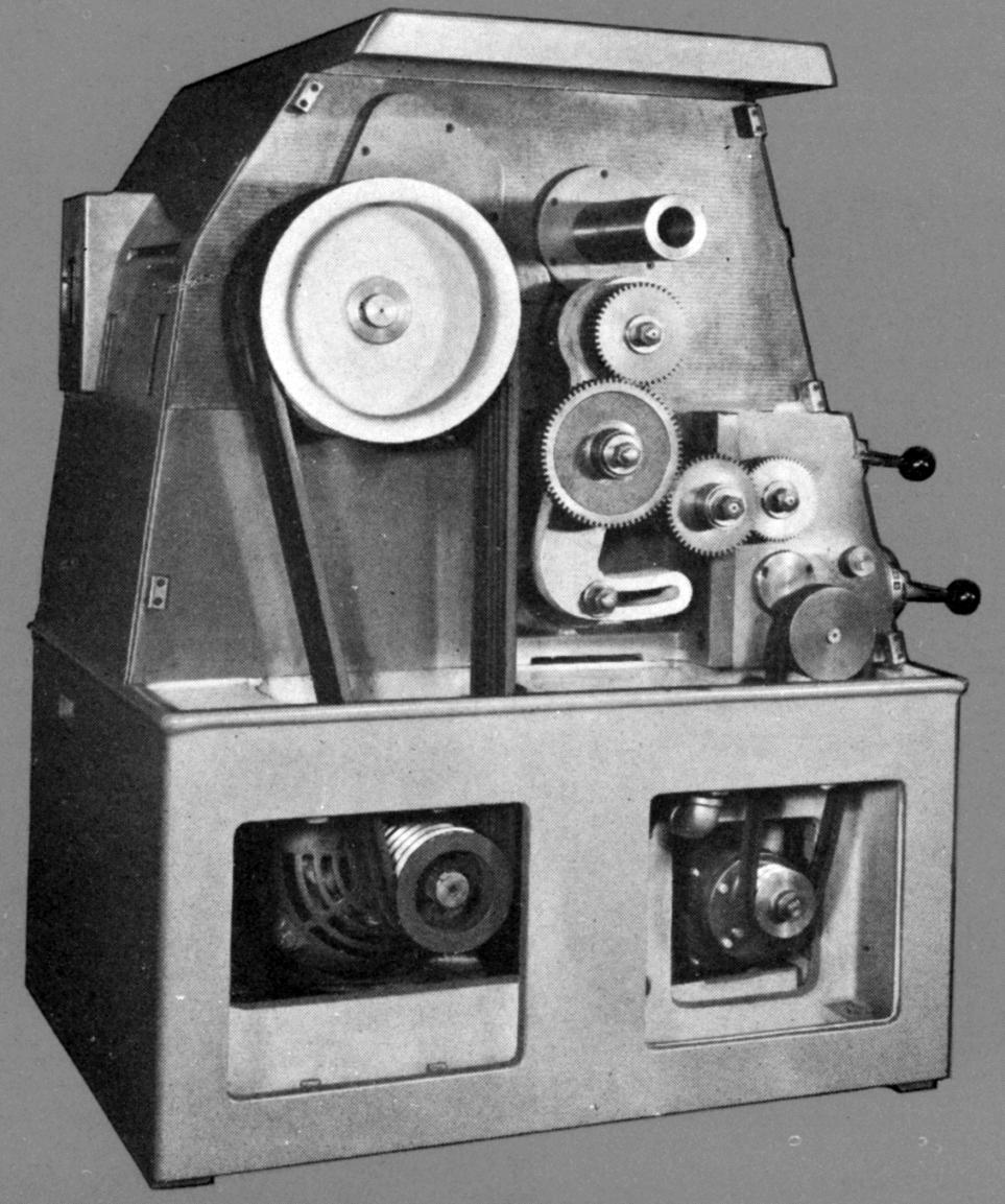
Springfield Model S. Available in two sizes - 16" x 30" "heavy duty" and 20" x 54" "medium duty", both Model S lathes were of identical appearance
Continued:
Headstock
A useful range of twenty-four spindle speeds was provided, the customer being offered a choice from three ranges, low, standard and high (though others could be provided if asked for) with each driven by its own motor:
Low: 1200 r.p.m. 10 h.p. motor giving 10 to 670 r.p.m.
Standard: 1200 r.p.m. 15 h.p. motor giving 15 to 1005 r.p.m.
High: 1800 r.p.m. 20 h.p. motor giving 22 to 1507 r.p.m.
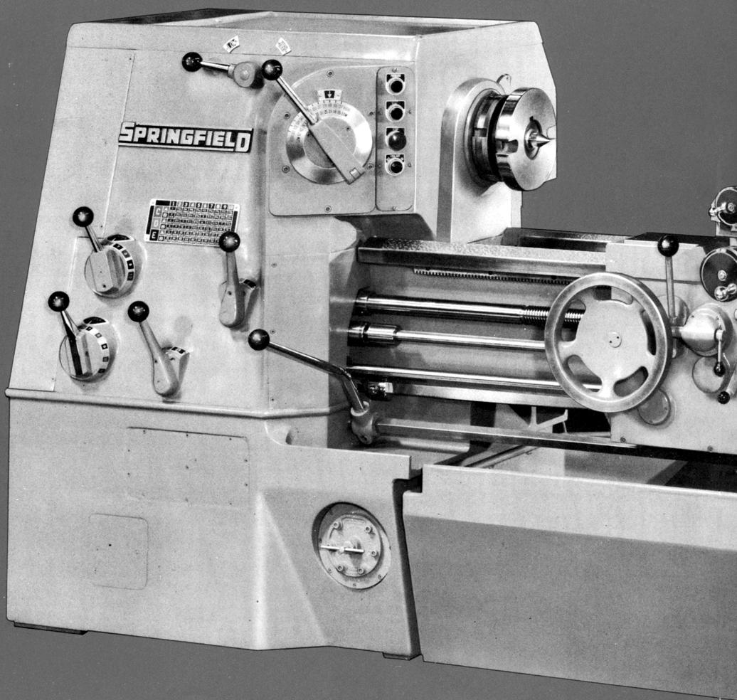
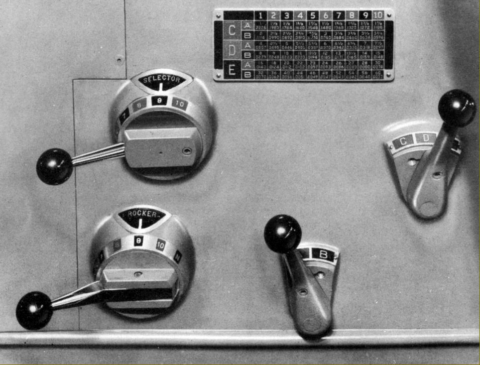
Spindle speeds were changed by just two headstock-mounted levers: one to select high or low range the other engraved with the twenty-four speeds in two colour-coded bands.
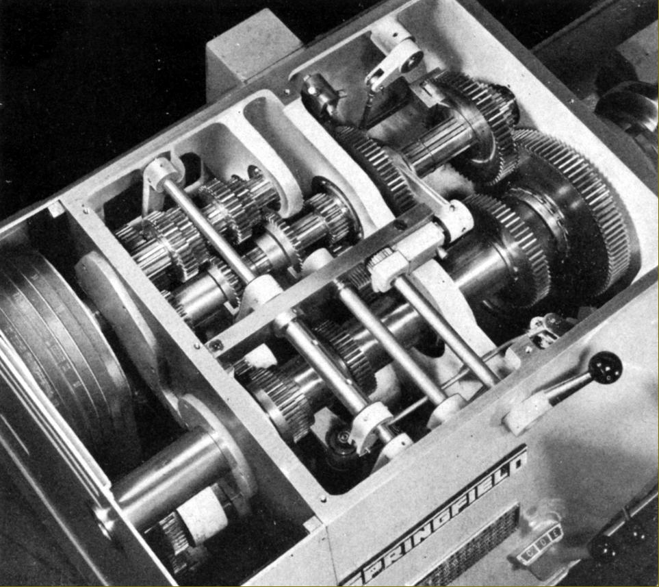
Strongly built, the box-section headstock held hardened and ground gears in a high-quality alloy steel with the 1.75-inch bore spindle (with a No. 4 Morse taper socket and L1-size Long-taper drive nose) running in two Timken high-precision taper roller bearings at the front and a single cylindrical roller bearing at the rear - this commonly-used arrangement allowing the spindle to expand safely as it warmed up. As an alternative - and probably intended for use only on the high-speed model - the customer could specify a spindle running in two precision ball bearings at the front and a cylindrical roller bearing at the rear. Lubrication was by a mechanical pump that lifted oil from a baffled sump in the plinth below the headstock (where the effect was to cool it) distributing it in the form of a filtered mist into the headstock interior and as a cascade into the screwcutting and feeds' gearbox.
Screwcutting and power feeds
Fully enclosed with a sump in its base and a pump that supplied oil to the bed and cross-slide ways, the screwcutting and power feed's gearbox had all-lever operation (there was no sliding tumbler) and drove a 1.5-inch diameter leadscrew with a pitch of 4 t.p.i. (held in tension between thrust bearings). The box, which could generate sixty threads and rates of feeds without changing or demounting any of the changewheels, was fitted as standard with just inch pitches - though an all-metric box and metric leadscrew were options, as was a set of metric translation wheels for the inch gearbox. The ordinary threading range was from 1 to 60 t.p.i., with feeds from 0.0037" to 0.2228" per rev. longitudinal. However, as an option it was possible to specify feeds and pitches arranged from 0.0018" to 0.1114" and 2 to 120 t.p.i. respectively.
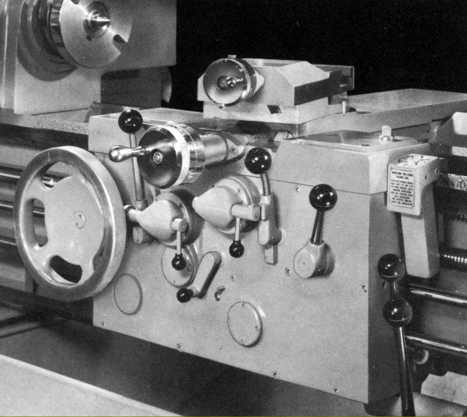
Control of the power sliding and surfacing feeds was by individual, apron-mounted levers, these being highly effective and of the easy-to-use, lift-to-engage clutched type (similar to those employed on several American makes including the Monarch 10EE) with, of course, safety interlocks to prevent inadvertent engagement of both. Incorporated within the apron was a multi-disc, oil-immersed clutch that provided a means of reversing the feed direction - on toolroom versions of the lathe the control for this was positioned on the apron but on others headstock mounted - though doubtless the makers would have been swayed by a customer's particular requirements and fitted whatever he desired. Two types of automatic disengage stops were offered: a simple type that worked on the screwcutting and power longitudinal drives in both directions (this was standard equipment to toolroom lathes) and a multiple-stop type for the other models carried on a square-section bar along the front of the bed - a fitting handy for production work. In addition, toolroom lathes had a micrometer depth stop for the cross feed and feed-rod stops for use at high spindle speeds.
Continued below:
|
|
|
|
|
|
|
 |
|
|
|
|
|
Continued:
Tailstock
Of unusual design and very heavy construction, the 15.5-inch long set-over tailstock was moved along the bed by a crank-handle turned gear that engaged with the bed rack and could be clamped by either a quick-action lever for ordinary work or by four top-mounted bolts for very heavy tasks. Operated by a handwheel set at an angle that faced towards the operator, the hardened and ground 3-inch diameter spindle could be moved through its nine inches of travel at two speeds and, thought it lacked a micrometer dial, was engraved with ruler divisions. Of the split-barrel type, the spindle lock was very powerful and operated by an unusually long lever. Available as options were built-in rotating (live) centres and air or hydraulic operation of the spindle.
Accessories
All version of the lathes were supplied with a steady rest, thread-dial indicator, a round toolpost, a tang-slot tailstock spindle and the necessary wrenches and an operator's handbook. In addition a very comprehensive range of accessories was offered that included (in addition to those already mentioned in the text): alternative higher and lower speed ranges; sub headstocks (mounted in front of the ordinary to give very low speeds); coolant systems; steady rests in various capacities (1/2" to 4", ½" to 6" and 6" to 10"); power rapid traverse to the carriage only or to carriage and cross slide; micrometer and multiple rotating carriage stops; a ball stop on the cross feed; taper turning; plain and universal relieving attachments; 4-way, and quick-set tool posts; collet chucks of the spindle-nose and drawbar type; face and drive plates; metric cross and top slide nuts, screws and micrometer dials; a CamLock spindle nose; hydraulic contouring attachment for semi-automatically contouring work pieces from templates; hydraulic reproducing attachment for plain and compound three-dimensional profiling from templates or samples; clever variable-speed electrical drives interlocked with the tool slides to give a constant peripheral speed to work when facing or contouring; 4-jaw chucks and, of course, power-driven and conventional 3-jaw chucks..
|
|
|
|
|
|
|
 |
|
|
|
|
 |
|
|
|
|
|
|
Spindle speeds were changed by just two headstock-mounted levers: one to select high or low range the other engraved with the twenty-four speeds in two colour-coded bands.
|
|
|
|
|
|
|
 |
|
|
|
|
|
|
Headstock lubrication schematic
|
|
|
|
|
|
|
|
|
|
|
 |
|
|
|
|
|
Rear view showing the coolant pump (with snap connectors) mounted on the back of the slide-out chip tray
|
|
|
|
|
|
|
 |
|
|
|
|
|
|
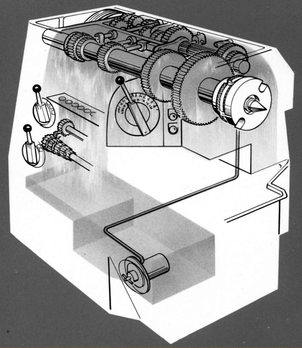
Inside the headstock. A useful range of twenty-four spindle speeds was provided, the customer being offered a choice from three ranges, low, standard and high (though others could be provided if asked for) with each driven by its own motor:
Low: 1200 r.p.m. 10 h.p. motor giving 10 to 670 r.p.m.
Standard: 1200 r.p.m. 15 h.p. motor giving 15 to 1005 r.p.m.
High: 1800 r.p.m. 20 h.p. motor giving 22 to 1507 r.p.m.
|
|
|
|
|
|
|
 |
|
|
|
|
|
|
Sealed screwcutting and feeds' gearbox with all-lever control
|
|
|
|
|
|
|
 |
|
|
|
|
|
|
Apron with individual, clutched controls for the power sliding and surfacing feeds
|
|
|
|
|
|
|
 |
|
|
|
|
|
|
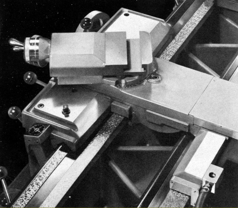
Carriage assembly with T-slotted top slide
|
|
|
|
|
|
|
 |
|
|
|
|
 |
|
|
|
|
|
|
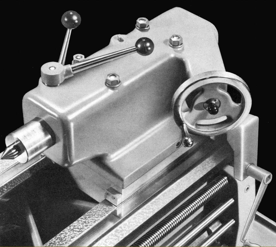
Of unusual design and very heavy construction, the 15.5-inch long set-over tailstock was moved along the bed by a crank-handle turned gear that engaged with the bed rack and could be clamped by either a quick-action lever for ordinary work or by four top-mounted bolts for very heavy tasks.
|
|
|
|
|
|
|
 |
|
|
|
|
|
|
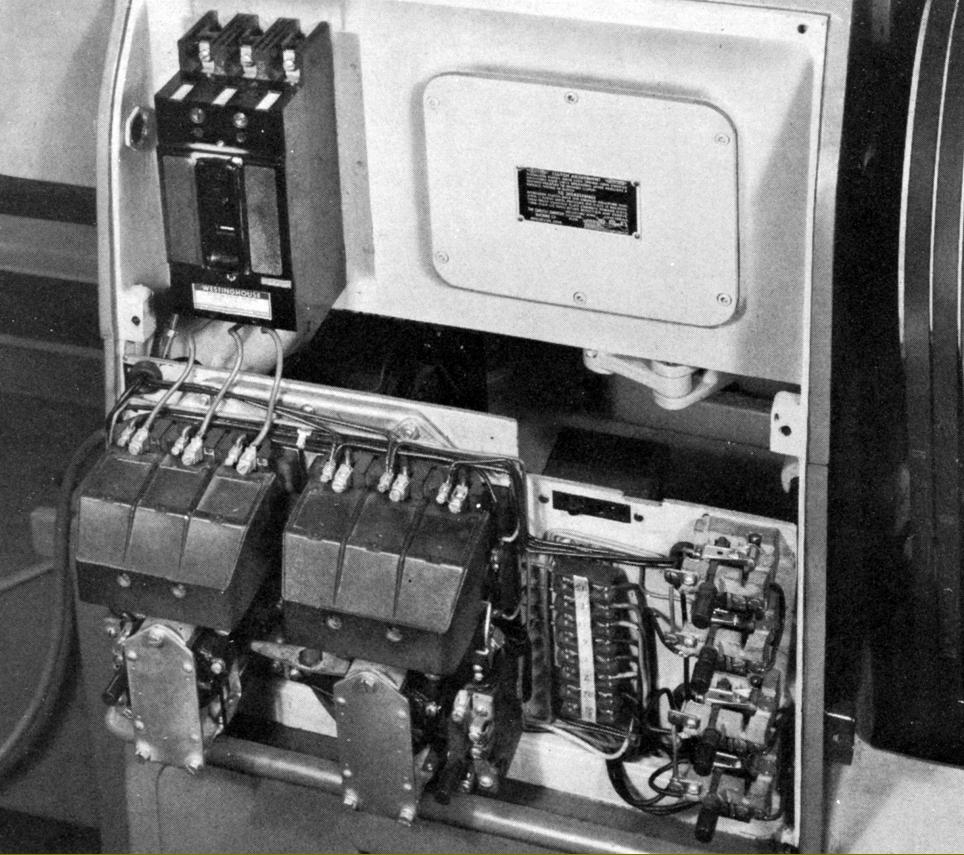
Electrical equipment mounted in a box at the back of the headstock
|
|
|
|
|
|
|
|
|
|
|
|
|
|