 |
|
|
|
|
|
|
|
|
|
|
|
|
|
|
|
|
|
|
|
|
|
|
|
|
|
|
|
|
|
|
|
|
|
|
|
|
|
|
|
|
|
|
|
|
|
|
|
|
|
|
|
|
|
|
|
|
|
|
|
|
|
|
|
|
|
|
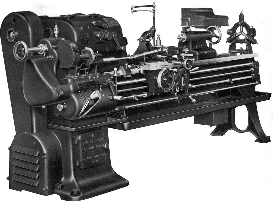
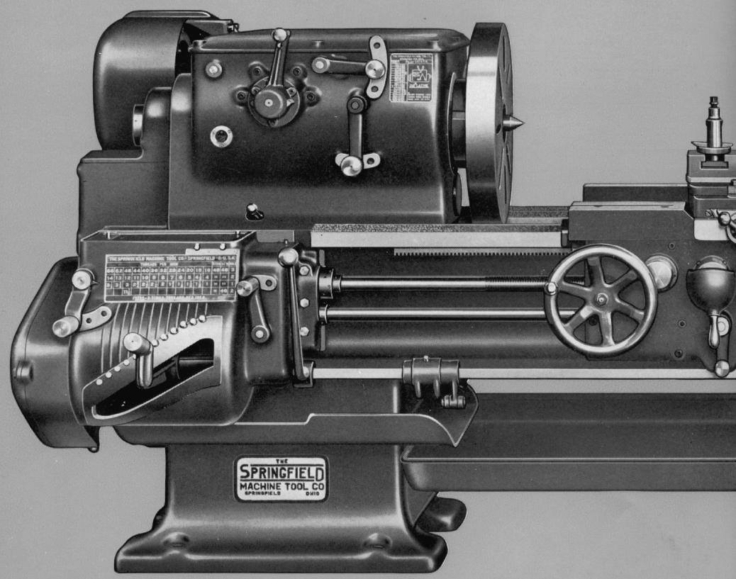
Well-designed and beautifully constructed, Springfield lathes from the 1930s and 1940s were all of the geared-head type (no open flat-belt drive types were offered) and built in versions that reflected their intended function. Built with swings of 14", 16", 18", 20", 22", 24", 27" and 30" and advertised variously as "Standard", "Tool Room" and "Super Duty" types, all were of very similar layout and design - though with detailed changes to reflect their intended function, for example, "Tool Room" versions differed from the "Standard" in having a feed-rod reverse to the carriage drive and a relieving attachment while the two "Super Duty" models were built only in 20" and 22" sizes (with actual swings of 20.5" and 22.5") and enjoyed a genuinely superior specification that was not the result of some meaningless advertising "puff". Driven by a 7.5 to 10 h.p. motor using five V-belts, their powerful headstocks had thicker walls than standard and were offered with a choice of either spur gears with ground teeth or hobbed and lapped helical gears - in both cases being drop-forged from carbon-chrome molybdenum steel. Lubrication was by splash and pump, oil being sprayed over the gears and into bearings; lubricant was lifted from a reservoir within the headstock-end plinth - this method helping to cool the oil. The heavy, carbon chrome molybdenum steel spindle was ground all over, and usually supplied with an American long-nose taper in an L2 size (though a thread was offered as an unlikely-to-be-chosen option) and ran in selected, precision-grade Timken taper roller bearings. All other shafts were splined, hardened, ground and supported in ball races.
Continued below:
|
|
|
|
|
|
|
 |
|
|
|
|
|
|
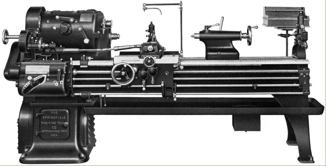
Standard and "Tool Room" Lathes with 14", 16", 18" and 20" swings
Although many makers offered what they claimed was a "range" of lathes that differed in centre height, many were often based upon just one bed with headstock, saddle and tailstock (plus one or two other minor castings) increased in depth as necessary. Springfield's approach was more honest and limited, to a great extent, the use of interchangeable parts - each type being build to an exact specification and generally with its own, dedicated castings. In this respect the 14" and 16" lathes each had their own bed casting (with hand-scraped V and flat ways and deep cross webbing between the walls) - 14.875" wide and 10.875" deep for the former and 16.75" wide and 11.75" deep for the latter - while the 18" and 20" types shared the same bed, 18.5" wide and 13.875" deep. Beds were all straight, without the option of a gap, and cast in Springfield's own foundry using a mixture of cast iron with 40 to 60% steel together with nickel and chrome additives. Headstocks were similarly arranged but with the two smaller lathes sharing the same internals (a spindle with a 1.5625" bore and 2.75" threaded nose) and the two larger likewise - in this case with a 1.8125" bore spindle carrying a 3.5-inch diameter nose. Nose threads are unknown, but later models did have the option of the stiffer (and safer in reverse) American long-nose taper, often not specified in the literature but usually of either an L1 or L2 fitting.
As standard all models were offered with an 8-foot long bed, this giving, on the 14" model, 56.75" between centres; on the 16" lathe 49.75" and on the 18" and 20" versions the same 42". Longer beds could be ordered, in increments of 12", and although the makers listed no maximum, this is likely to have been around 96" between centres with the longer versions given a third, central supporting leg.
At first, drive to the headstock input pulley was often arranged individually to suit a customer's particular requirements, a choice being offered of flat belt from a factory's existing line-shafting or by a motor carried on top of the headstock or inside the headstock end bed-support plinth. With the motor attached to the lathe a variety of systems could be ordered including by "silent chain", a short flat belt or through straight-cut gears - one often being in fibre to help quieten the drive. The 1920s was a decade of experimentation and a time of flux as makers struggled to come to terms with an increasing demand for machines tools with integrated drive systems. By the early 1930s the matter was solved by the introduction of reliable V-belts when, from small to large, lathes could be equipped with single or multiple pulleys to transmit the required 0.25 to 10 h.p. from motor to the headstock input pulley. As this much more reliable and compact system became widespread it was found that motor power could be increased, in the case of Springfield lathes by around 50% such that the 14", originally specified with a 2 to 3 h.p. motor, was instead required to have (with 4 V-belts) from 3 to 5 h.p. and, so equipped, the 12 speeds spanned 11 to 400 r.p.m.; the 16" shared the same motor requirement (though with a 6-step V-pulley) with its 12 speeds running from 10 to 406 r.p.m. while 18" and 20" both required rather more power, the makers suggesting from 5 to 7.5 h.p. (with 6 V-belts) to give 12 speeds from 10 to 380 r.p.m. Quoted spindle speeds assumed a motor running at 1200 r.p.m. with the headstock input pulley turning at 500 r.p.m. As the years passed speeds were increased slightly: the two smaller models having around 16 tp 600 r.p.m. and the larger pair 11 to 423 r.p.m.
Holding 14 drop-forged, heat-treated gears running in an oil bath (supplemented on later models by a pumped supply that sprayed oil over the gears and into the bearings) the headstock held a spindle running in either plain bronze "sleeve" bearings or Timken taper rollers. A disc-type friction clutch (that might have included a brake) was built into the headstock input pulley and controlled by a lever positioned just outboard of the screwcutting and feeds' gearbox or, on long-bed versions, with an additional lever pivoting from the apron's right hand-face and travelling with it, the motion being passed back to the headstock by a long rod.
Double-walled with shafts supported at both ends, the apron held an oil sump from which lubricant was lifted automatically by a pump linked to the movement of the carriage handwheel. Oil, forced through felt strainers, was fed to the apron gears and bearings and the lathe bed and cross-slide ways.
Power sliding and surfacing feeds were driven by a slotted feed rod, this passing through the centre line of an apron-mounted bevel gear where it drove, via keys, a mating gear at each side of the bevel gear - these being engaged by a sliding dog clutch that enabling feed direction (along or across) to be reversed without stopping the lathe. A valuable aid to the operator was a knock-off rod, fitted with adjustable stops that acted to disengage the drive when moving under power to the left or right - the leadscrew drive having the same facility for use when screwcutting. Apron gears ran in constant mesh with just a single selector required to change from longitudinal to cross feed, the engagement being through individual, lever-operated friction clutches operated by lift-up handles. Leadscrews were sized appropriately to each lathe: that fitted to the 14" and 16" lathes being 1.25 inches in diameter with 6 threads per inch (t.p.i.) and, on the 18" and 20" models, one slightly larger at 1.375" x 4 t.p.i. Leadscrews were grasped by split nuts fitted replaceable babbit (white-metal) inserts, so allowing easy and inexpensive replacement - however, the makers also listed the option of nuts in bronze and cast iron. Of the ordinary Norton quick-change type the screwcutting and feeds' gearbox appears to have been common across the range and, on 14" and 16" lathes generated pitches from 1.5 to 80 t.p.i. with longitudinal feed rates spanning 0.004" to 0.222" per revolution of the spindle and cross feeds set at half that rate. The pair of larger lathes offered pitches from 1 to 56 t.p.i. and longitudinal feed rates from 0.0045" to 0.250" per revolution of the spindle with power cross feed set to be twice as fine.
Continued below:
|
|
|
|
|
|
|
 |
|
|
|
|
|
|
Continued:
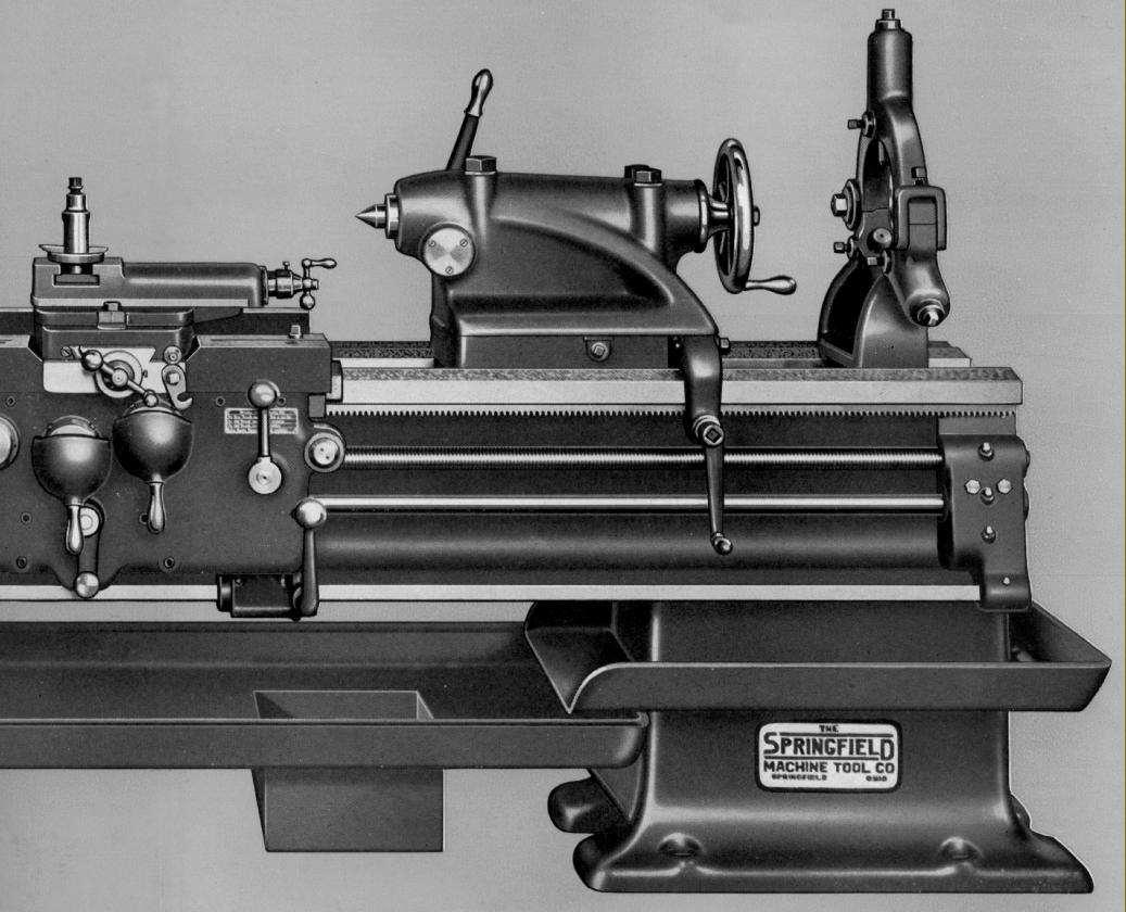
Fitted with long wings at each side of the hand-scraped cross-slide ways, the saddle was gibbed to the bed with a full-length strip at the rear and two short ones at the front; felt wipers were fitted to clean the bed ways. Of the short type (in order to mount an extension section at the rear to pick up a taper-turning unit) the cross slide was surmounted by a 360° swivel top slide - both having tapered gip strips. Micrometer dials were, as was common at the time, very small and hard to read at a glance - though at the time many skilled turners would still have relied upon callipers set "just so" when gauging the process of a job.
Tailstocks were given appropriate Morse tapers and travels for each size of lathe, the 14" model having a 2" diameter spindle with 6" of travel and a No. 3 Morse socket; the 16" lathe a No. 4 Morse taper with a 2.25" diameter spindle and 7.5" of travel - while both the 18" and 20" version had a No. 4 Morse spindle 2.6875" in diameter with a travel of 8.5". Detail design of tailstocks varied from model with some having a simple eccentric cross shaft to act as a bed lock while others used two through bolts for even greater security. All could be set over on their base for the turning of slight tapers - and proper split clamps, some acting vertically, others horizontally, were used as spindle locks.
Approximate net weights of 14" and 16" lathes with a standard 6-foot bed were, respectively: 3100 lbs (each extra foot adding 130 lbs) and 3400 lbs (each extra foot adding 140 lbs) The 18" and 20" with 8-foot bed weighed, respectively: 4900 lbs (each extra foot adding 160 lbs and 5200 (each extra foot adding 160 lbs).
Continued below:
|
|
|
|
|
|
|
 |
|
|
|
|
|
|
Springfield 30" Medium Duty
Standard and "Tool Room" Lathes with 24", 27" and 30" swings
Identical in both general layout and most elements of detail design to the Company's smaller lathes, the 24", 27" and 30" swing models were of massive construction and considerable mass, the three machines weighing, respectively, 12,000, 12,400 and 13,500 lbs. This relatively small increase from smallest to largest is a clue to their construction, the two smaller models being almost identical apart from the thickness of the castings needed to increase the centre height - beds being 23.625 inches wide and 17" deep on the two smaller models, but considerably more massive on the largest model at 28" wide and 19.25" deep. All three were supplied in basic form with just 48" between centres but, as with the smaller lathes in the Company's range, longer beds in 12-inch increments were available up to an unknown limit - but probably around 96" between centres with the addition of a central support foot on the longer models.
All headstocks held gears of helical form (there being no listed option for spur gears) and a Timken taper-roller bearing supported spindle bored through 2.375" with a spindle nose (of unknown thread pitch) 4.5" in diameter. Motors suggested by the makers as being suitable for all sizes varied from 10 to 15 h.p. running at 1200 r.p.m. , these giving (for all versions) 12 spindle speeds that ranged from 9 to 280 r.p.m.
Screwcutting and power feeds were supplied by the usual Norton quick-change gearbox, sliding feed rates being from 0.006" to 0.356" per revolution of the headstock spindle - screwcutting pitches were not listed in the technical literature but would have run from something like 1.5 to 40 t.p.i.
In all other respects the larger models were the same as the smaller with oil from the apron being pumped to bed and cross slide ways, automatic disengage fitted to the power and screwcutting feeds with engagement of the spindle clutch by levers positioned just outboard of the screwcutting gearbox and also, on longer-bed models, a second lever pivoting from the right-hand face of the apron.
Continued below:
|
|
|
|
|
|
|
|
|
|
|
|
|
 |
|
|
|
|
|
|
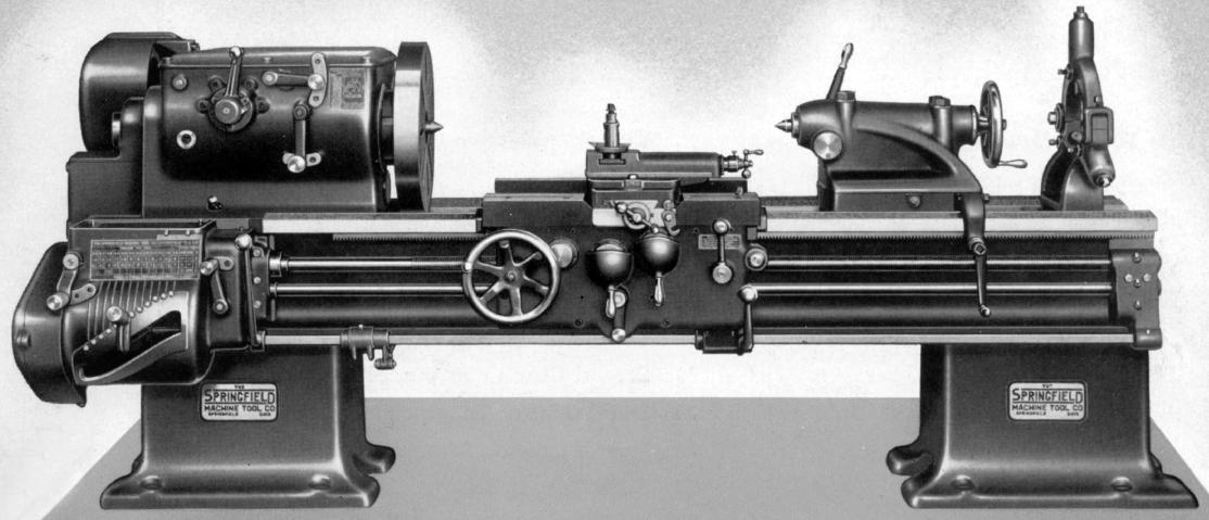
Springfield 20" Super and 22" standard
|
|
|
|
|
|
|
 |
|
|
|
|
|
|
20" Super and 22" standard
|
|
|
|
|
|
|
 |
|
|
|
|
|
|
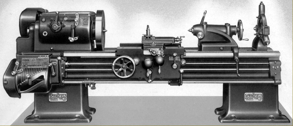
Springfield 20" Super and 22" standard
|
|
|
|
|
|
|
|
|
|
|
|
Springfield 20" Super Duty and 22" Standard
Built during the 1930s and 1940s as a 20" model, the Super Duty was identical to the contemporary 22" Standard in all but centre height, the intention being to provide a lathe suitable for especially heavy work and rapid rates of metal removal, its centre height being slightly reduced to stiffen the structure. The makers explained: this machine was designed especially for heavy work where larger swings were not necessary, and of course, all the features and dimensions are very liberal in order that the machine will perform correctly on work normally considered too heavy for regular 20" lathes. With actual swings of 20.5" and 22.5", both lathes were of a genuinely superior specification and not just the result of some advertising "puff".
With the usual Springfield V and flat ways and deep cross webbing between the walls, the bed was 20.25" wide and 14.5" deep - and so rather more massif than that used on the ordinary 14" to 20" models. Beds were all straight, without the option of a gap, and cast in Springfield's own foundry using a mixture of cast iron with 40 to 60% steel and nickel and chrome additives. As standard the lathe admitted 48" between centres, but could also be supplied in foot increments up to around 96 inches - possibly more - with the likelihood that a central support would have been fitted.
Driven by a 7.5 to 10 h.p. motor using six V-belts, their powerful, 16-speed headstocks had a bed-fastening length of 28.75", thicker walls than standard and could be had with either ground-finish spur gears or hobbed and lapped helical gears - in both cases drop forged from chrome molybdenum steel and heat-treated. Lubrication was by splash and pump, oil being sprayed over the gears and into bearings having been lifted by a pump from a reservoir within the headstock-end plinth - this method helping to cool the oil. The heavy, carbon-chrome molybdenum steel spindle was ground all over and normally equipped with an American long-nose taper in an L2 size - though a thread was offered an unlikely-to-be-chosen option - and ran in selected, precision-grade Timken taper roller bearings. All other shafts were splined and supported in ball races. With an internal "backgear" reduction of 6.94 to 1 and an input pulley speed of 500 r.p.m., spindle speeds ran from a low of 12 to a high of 506 r.p.m. engagement of the drive was by a disc friction clutch built into the ball-bearing suspended headstock input pulley and controlled by a lever positioned just outboard of the screwcutting and feeds' gearbox or, on long-bed versions, with an additional lever pivoting from the apron's right hand-face and travelling with it, the motion being passed back to the headstock by a long rod.
Double-walled with shafts supported at both ends, the apron held an oil sump from which lubricant was lifted automatically by a pump linked to the movement of the carriage handwheel. Oil was forced through felt strainers and fed to the apron gears and bearings and the lathe bed and cross-slide ways. Power sliding and surfacing feeds were driven by a 1.25" diameter slotted feed rod, this passing through the centre line of an apron-mounted bevel gear where it drove, via keys, a mating gear at each side of the bevel gear - these being engaged by a sliding dog clutch that enabling the turner to reverse the feed direction (along or across) without stopping the lathe. A valuable aid to the operator was a knock-off rod, fitted with adjustable stops that acted to disengage the drive when moving under power to the left or right - the leadscrew drive having the same facility for use when screwcutting. Apron gears ran in constant mesh with just a selector to change from longitudinal to cross feed, the engagement being through individual, lever-operated friction clutches operated by lift-up handles. With a pitch of 4 t.p.i. and a diameter of 1.625 inches, the leadscrew was grasped by split nuts fitted replaceable babbit (white-metal) inserts, so allowing easy and inexpensive replacement; however, the makers also listed the option of nuts in bronze and cast iron.
Of the ordinary Norton quick-change type the screwcutting and feeds' gearbox was of identical layout to that used on the Company's other lathes and offered 36 pitches from 1 to 56 t.p.i. and 36 rates of power sliding and surfacing feeds, the former at 0.004" to 0.350" per revolution of the spindle and with the latter arranged to be twice as fine.
Heavily built to match the rest of the lathe, the tailstock had a spindle 3.25" in diameter with a No. 5 Morse taper socket and a travel of 12". An oil reservoir on the barrel supplied lubricant not only to the moving parts and bearings but also to the underside where it contacted the bed. There were double bed and spindle clamps and the unit was moved along the bed by a pinion that engaged with the bed-mounted rack used by the carriage..
|
|
|
|
|
|
|
|
|
 |
|
|
|
|
|
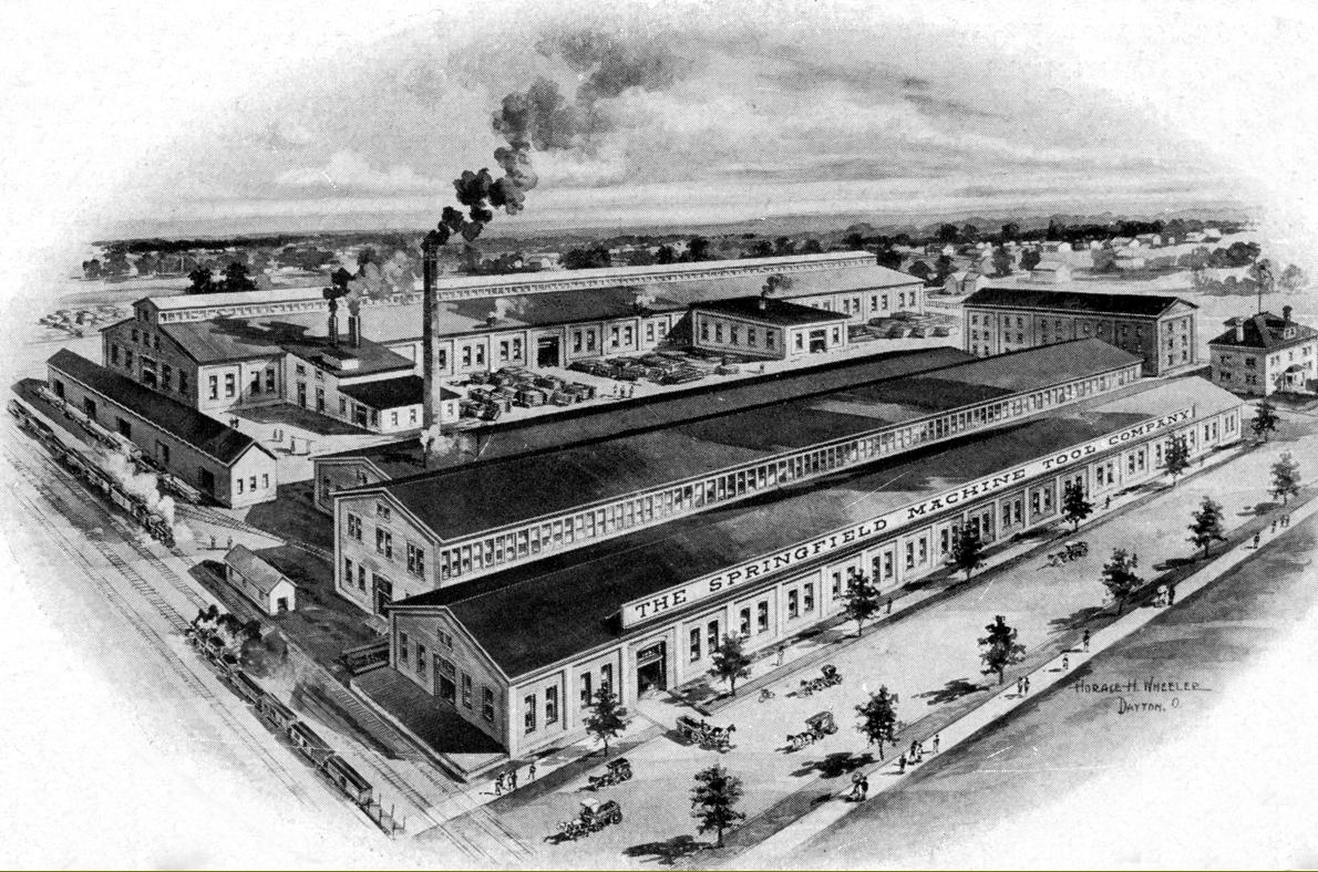
An early view of the Springfield works: steam rail, horse-and-cart transport with not a motor vehicle in sight
|
|
|
|
|
|
|
|
|
|
|
|
|