email: tony@lathes.co.uk
Home   Machine Tool Archive   Machine-tools Sale & Wanted
Machine Tool Manuals   Catalogues   Belts   Books  Accessories

Schaublin Type 53 Milling Machine
Schaublin Milling Machines Home Page  Schaublin 11   
Schaublin SV11-A & SV11-B   Schaublin SV12   
Schaublin 13 - dismantling the column   Schaublin 22
Schaublin Type 51   Schaublin Type 52   Schaublin Type 53   
Schaublin Type 53N

An Operating, Maintenance and detailed Parts
Manual is available for the Type 53 miller

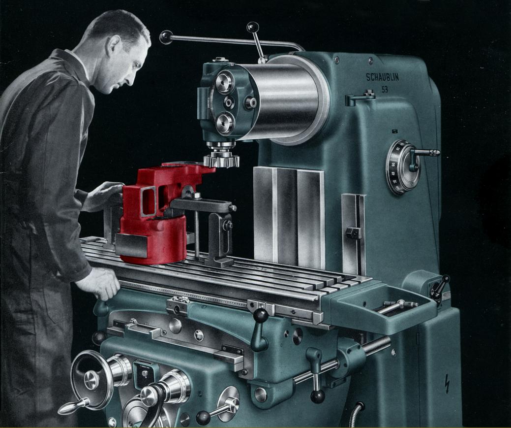
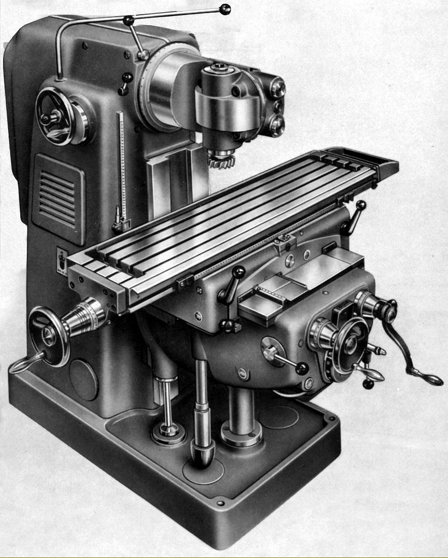
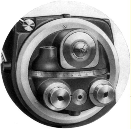
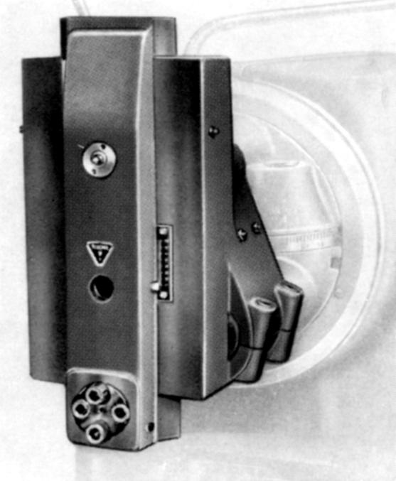
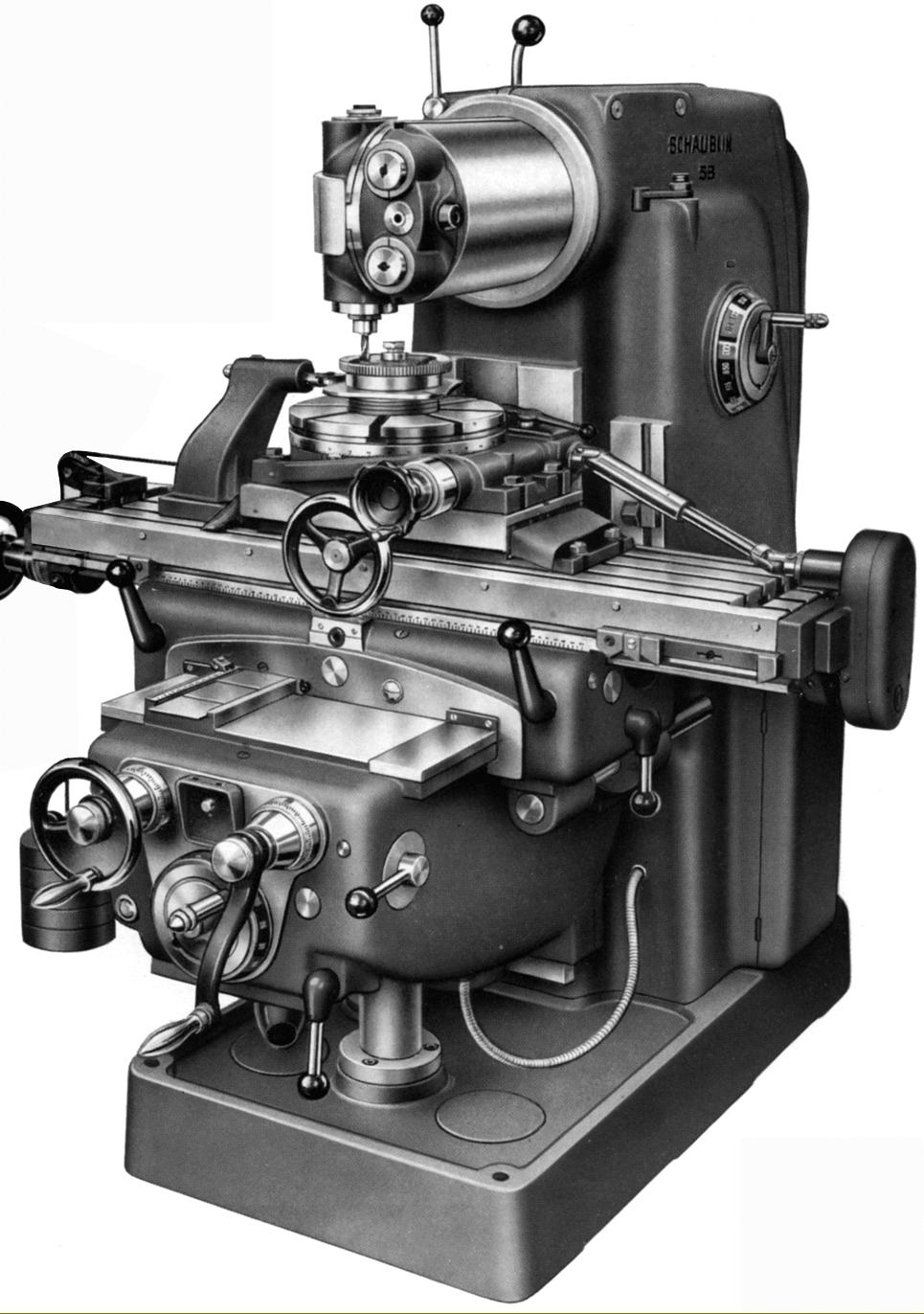
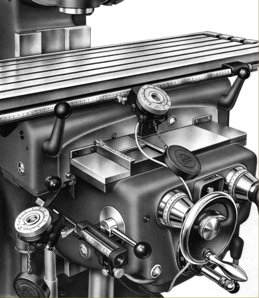
Developed from the Type 51 and Type 52 of the mid 1940s, the Schaublin 53 Universal High-precision Milling Machine was an expensive proposition that, even so, found favour around the world as a highly versatile, wonderfully accurate and reliable machine tool. Heavily built - it weighed 1700 kg - the Type 53 was based on a patented design and used a massive (ventilated) main column and foot in cast iron to house the head and coolant motors, the spindle drive gearbox (complete with a combined double-plate steel-on-steel clutch and brake unit by Stromag), the table-feed gearbox, the special V-belt driven oil-mist mechanism (a compressor and atomizer) for lubricating the horizontal milling-head cylinder, all the electrical switchgear and, formed as part of the base, a 50-litre (11-gallon) coolant tank.
While the column, drive system, knee and table were conventional enough, the head arrangement was, possibly, unique and gave the machine an ability to switch quickly between vertical and horizontal modes. Driven by bevel gears, the various heads were carried on the end of a sliding horizontal cylinder 240 mm in diameter that could be rotated through 360°, locked at 15° intervals and with an in-and-out travel of 300 mm. The spindle nose was an ISO 40 (the steep taper of which allowed the easy release of tooling) to specifications VSM 33931, size 44, or DIN 2079, size 40 with a positive, 2-key drive. The fitting was large enough to take a variety of useful adaptors down to 1, 2, 3 or 4 Morse and also carry (in suitable holders) Schaublin Type W20, W25 or E25 collets. Fitted with a 4 h.p. motor running at 1500 r.p.m., both standard and high-speed heads were available, each driven from the main spindle. The former, with its fixed quill, had eighteen speeds of 38, 48, 60, 72, 92, 115, 140, 172, 212, 270, 340, 422, 515, 650, 800, 970, 1220 and 1510 r.p.m. and could be rotated on the end of the horizontal housing with an eccentric lock that gave precise clamping every 30 and 50° while also allowing any intermediate position to be set. Originally available in two versions - one with and the other without a fine-feed to the 80 mm travel quill (types 1120 and 1100) - the 33 kg high-speed head was designed to take Schaublin E25 collets and had the same number of speeds as the standard head but spanning 150 to a usefully high 6000 r.p.m. Both versions had a quick-action drilling lever and, as an option, a most unusual accessory - automatic power feed to the quill driven by a flexible cable from a worm-and-wheel gearbox clamped to the right-hand end of the table's feed screw.
Spindle speeds, provided by a gearbox that had both oil-bath and spray lubrication (the latter by an immersed piston pump) were selected by a Cincinnati-type rotary control on the right-hand face of the column with every half-turn of the crank, in either direction, giving the next higher or lower rate with the dial automatically showing that selected. Lubrication of the horizontal cylinder and head was by pressure-fed mist, the benefits claimed including a cooling effect and an improved and more uniform distribution of the oil.
When switching to horizontal milling, instead of having to lift and mount a heavy overarm and drop bracket the operator simply pulled a pair of 50 mm diameter ram supports out from the face of the head with the cutter arbor (supplied in a number of lengths and diameters) being socketed into the horizontal spindle nose. While not as rigid as a more conventional system for most purposes it was, according to experienced users, perfectly adequate - especially if the optional twin bracing bars between arbor and saddle were fitted.
Continued below:

Continued:
Fitted, rather inconveniently, with a (disengaging) handwheel at its left-hand side only, the 1100 x 255 mm (43.25" x 10") table had four T-slots on 50 mm (2") spacing and 700 mm of longitudinal travel, 250 mm across and 430 mm vertically - the figures remaining unaltered when used under power. The eighteen rates of ordinary feed were provided by a gearbox, driven from an extension to the main spindle motor, and ranged from 12 to 1050 mm (0.47" to 41.3")/min longitudinally and in traverse and from 6 to 525 mm (0.23" to 20.6")/min vertically. The feed mechanism was protected by an overload clutch fitted to the main output spindle of the gearbox; this was unit non-adjustable and alerted the operator to its engagement by rattling noise. Rapids (on all axes) were powered by a separate 1.5 h.p.  2,800 or 1.6 h.p. 3,000 r.p.m. motor and, rather usefully, the spring-loaded push button on the knee that engaged them (it had to be held down of course to keep the drive engaged) could also be used as an inching control. Rates were set at 3500 mm (138")/min in both horizontal planes and at a more sensible and safe 1700 mm (69")/min vertically. Precise feed rates varied slightly over the years, through not by any significant amount. Rates of power feed were selected by a single dial on the front of the knee, its action duplicating that of the spindle-speed control with each half-turn in either direction producing the next higher or lower rate. Levers were used to engage the feeds, each causing the drive to travel in the direction of their movement and with those for the horizontal movement duplicated at each end of the saddle and linked together.
Working on both the ordinary and rapid feeds, fixed over-run and adjustable auto-disengage stops were fitted to each feed axis and, in addition to (reasonably large) micrometer dials fitted with zeroing verniers, each feed was also equipped with a finely inscribed ruler with, on the vertical motion, a magnifying glass to help achieve an accurate setting. The nut though which the longitudinal feed screw ran could be adjusted to remove play, though this involved some dismantling, but in the case of the cross-feed any slackness between nut and screw could only be corrected by machining both a cover plate and a sleeve assembly - not something that the average user would be inclined to attempt.
Arrangements for lubrication were comprehensive with the feed gearbox in the knee oiled by a submerged piston-type oil pump, the saddle parts and longitudinal feed screw by an oil bath and the table and saddle slides and cross-feed feed screw by a hand-operated piston pump that drew oil from a reservoir. Oil for the highly stressed knee-lift screw was by a constantly circulating supply of oil drawn from a tank formed as an integral part of the casting that surrounded it, a similar system being employed for many years on Cincinnati millers.
In addition to the expected cutter holders, centre and cutter adapters, boring heads, swivelling and static-base machine vices and rotary tables and dividing heads, a number of useful accessories were available including a slotting head with its stroke adjustable from 0 to 7 mm (0 to 3.75") and stroke from 17 to 500 per minute; a rotary table power-feed attachment driven from the end of the table feed screw; a copy-milling attachment (used in conjunction with the powered rotary table); a centring microscope with built-in lighting; precision length-bar holders for each axis that also accepted dial-test indicators and other contemporary precision measuring systems including optical readers..

Schaublin Type 53 as manufactured in the early 1960s

A line of nearly completed Schaublin Type 53 millers

Horizontal milling set-up with the optional bracing bars in place

High-speed Head Type 1120 with both fine and rapid feeds to the quill

High-speed Head Type 1100 with just the rapid drilling-action to the quill

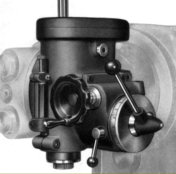
Item 1140A automatic quill feed for the high-speed head

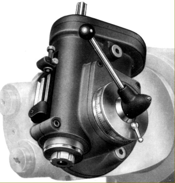
Item 1200 Slotting Head. The stroke was adjustable from 0 to 70 mm (0 to 2.75") and the rate variable between 17 to 500 per minute

Copy milling attachment (Item 6800). The unit consisted of a sliding base moving with great ease and sensitivity on line-contact balls; mounted on top was a powered rotary table with the part to be copied, usually some sort of cam or component of irregular shape, mounted directly beneath the part to be machined. The roller follower was kept in contact with the master by a weight attached to the moving slide.

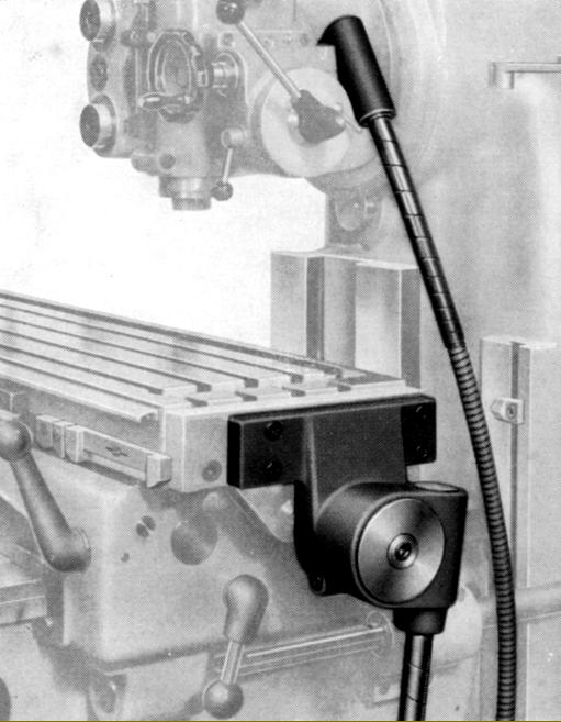
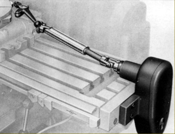
Item 1070 attachment for automatic drive of table-mounted accessories

Copy milling - detail of roller follower and cutter head

Contemporary precision measuring systems included these optical readers and finely engraved rulers

Inclinable Universal Dividing Head (Item 900) being used in conjunction with the automatic drive attachment (Item 940B) to mill a plate cam

Inclinable Universal Dividing Head (Item 900) being used in conjunction with the automatic drive attachment (Item 940B) to mill an bell cam

The Inclinable Universal Dividing Head, combined with its tailstock, being employed to machine a milling cutter between centres

Inclinable Universal Dividing Head (Item 900) and tailstock (Item 1000)

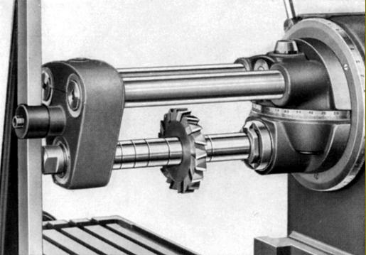
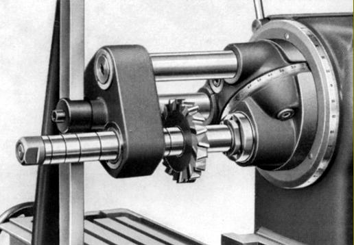
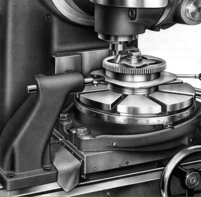
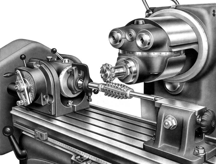
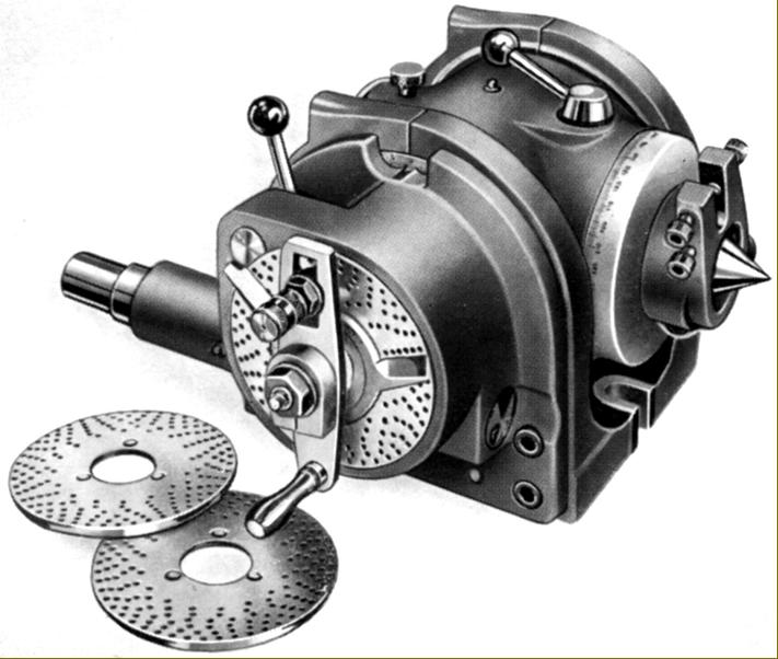
"Quadrant" and changewheels (Item 940B) for drive to the Universal Dividing Head Item 900. Supplied with the unit were 16 gears (24, 25, 28, 32, 36, 40, 44, 48, 56, 64, 72, 80, 86, 96, 100 and 112 teeth), a connecting shaft, drawbar and the required spacing rings, washers and fixing bolts.
The unit allowed the milling of helices, differential indexing and a direct drive to the spindle.

email: tony@lathes.co.uk
Home   Machine Tool Archive   Machine-tools Sale & Wanted
Machine Tool Manuals   Catalogues   Belts   Books  Accessories

Schaublin Type 53 Milling Machine
Schaublin Milling Machines Home Page  Schaublin 11   
Schaublin SV11-A & SV11-B   Schaublin SV12   
Schaublin 13 - dismantling the column   Schaublin 22
Schaublin Type 51   Schaublin Type 52   Schaublin Type 53   
Schaublin Type 53N

An Operating, Maintenance and detailed Parts
Manual is available for the Type 53 miller