|
Home Machine Tool Archive Machine-tools Sale & Wanted Robling Lathes Robling Mk. 2 Models 650 & 850 Robling Mk. 3A Robling Lathe Parts |
|
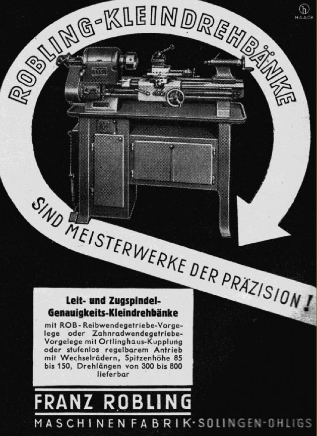
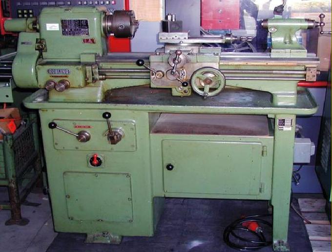
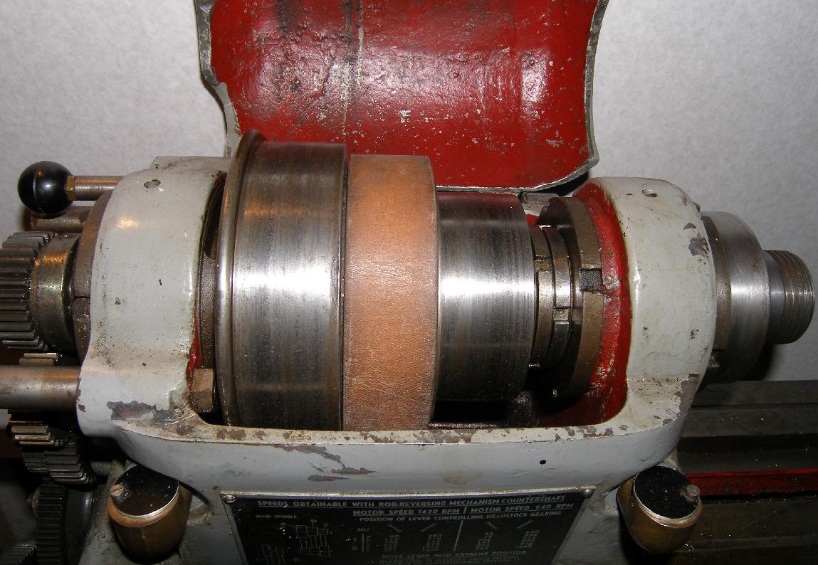
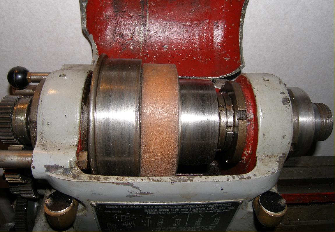
Originally makers of polishing equipment for bicycle manufacturers, the Robling lathe was made by Franz Robling Maschinenfabrik of Solingen-Ohligs, the centre of German knife and scissors production. A useful machine, of 300 mm swing by 500mm to 600 mm between-centres, this was their first lathe and designed in the 1940s and manufactured until the 1960s. Surprisingly, for a company new to proper machine tools, Robling were to sell somewhere around 2000 examples with many still at work today in both professional precision machine shops and those of the keener model and experimental engineer. Sales in the UK were handled through William Urquhart, of 1023 to 1027 Garratt Lane, Tooting Broadway, London S.W.17. The lathe shown in detail below is an early type, the Mk. 2 models had a number of significant improvements including: a 36 mm bore spindle, with a No. 5 morse taper nose, running in a roller bearing at the front and twin ball races at the rear (on earlier models, with bronze spindle bearings, the pulley ran in its own ball races to remove the effects of belt pull from the main bearings); a bed with deeper walls towards each end; a more reliable lever-operated 3-rate power-feeds and screwcutting gearbox; a heavier stand - cast-iron, as before but with a much larger enclosed plinth under the headstock; a more robust tailstock with barrel compression clamp; a much better apron with revised power-feed controls and a micrometer dial on the carriage handwheel. There was also a complete redesign of the cross-slide assembly with a greatly enlarged micrometer dial and the feed-screw support moved from a bracket bolted to the end face of the slide to a mounting on the front face of the apron - the feed-screw nut being repositioned on the underside of the cross slide. Hidden improvements included instant spindle reverse by means an Oertlinghaus gearbox with steel multi-plate forward/reverse clutches running in an oil bath - the drive working with commendable smoothness. The box was set so that reverse gear was a 1:6 ratio down from forward (or, if the motor was reversed, the other way round of course) - an arrangement particularly handy for screwcutting where the slow speed was used for generating the thread and fast reverse for returning to the start of the job. The lathe spindle could be made to revolve in the opposite direction without having to stop it first - simply moving the gearbox selector lever straight across into reverse did the job - a similar system also being employed on some Colchester lathes from the 1960s until the 1990s using either Oertlinghaus or Matrix clutches. In addition, a very useful spindle braking effect could be created by momentarily moving the gear selector lever through its neutral position into reverse. Although the 24 spindle speeds ran from a useful 55 to 1820 r.p.m. the method of obtaining the slowest 6 was unusual: the belt was moved to the low-range position, the electric motor reversed and - to make the spindle rotate forwards - reverse gear selected on the Oertlinghaus gearbox. Today, fitting a VFD (inverter drive) gets around this somewhat awkward arrangement - but does nothing to alleviate the fact that the final drive at low speeds is by a flat belt and not gears. Whilst flat belts are ideal for smooth driving at medium to high revolutions, at low speeds their ability to transmit large amounts of torque is limited. |
|
|
|
|
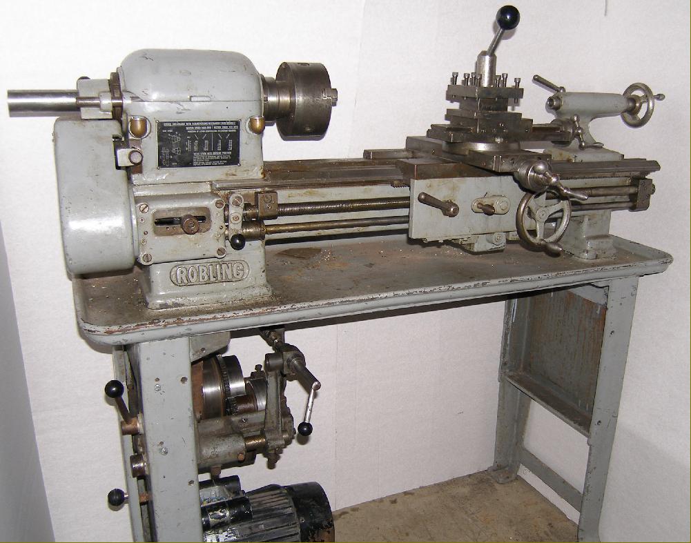
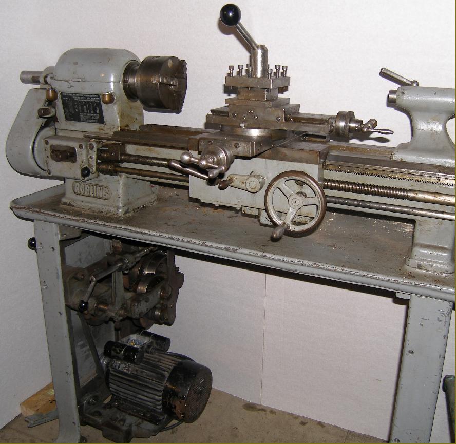
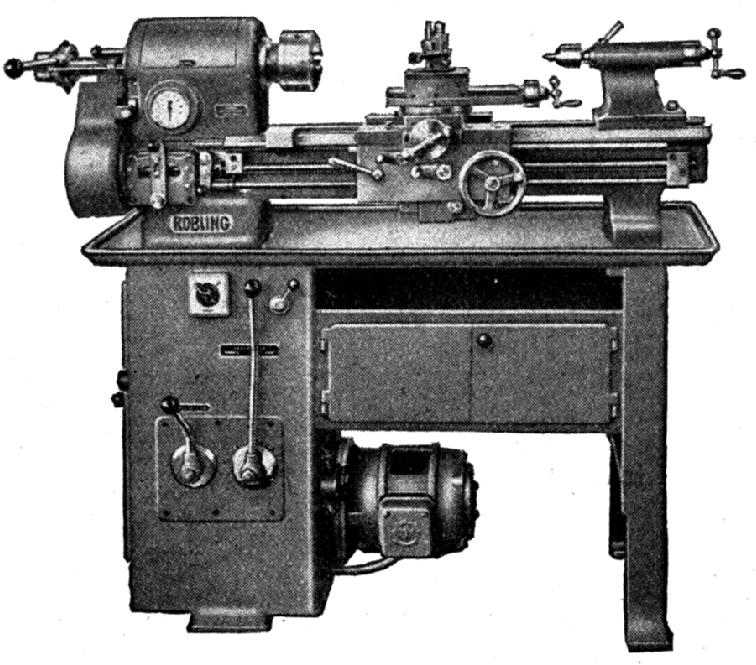
A Robling Mk. 2 showing a number of significant improvements including: a bed with deeper walls towards each end, an improved 3-speed power-feed gearbox, a heavier stand (cast-iron, as before) with a much large enclosed plinth under the headstock, a more robust tailstock with barrel compression clamp, a 36 mm bore headstock spindle running in roller races with a No. 5 morse taper nose, a substantial apron with revised power-feed controls and a micrometer dial on the carriage handwheel. There was a complete redesign of the cross-slide assembly with the feed screw moved from a bracket on its end to a mounting on the front face of the apron (the feed screw nut was let into the underside of the cross slide) and greatly enlarged micrometer dials. Hidden improvements included instant spindle reverse by means an Oertlinghaus gearbox with steel multi-plate forward/reverse clutches running in an oil bath - the drive working with commendable smoothness. The box was set so that reverse gear was at a 1:3 ratio down from the forward gear (or, if the motor was reverse, the other way round) - an arrangement particularly handy for screw cutting where the slow speed was used for cutting the thread and fast reverse for returning to the start of the job. The main drawback of this model was the absence of either a speed-reducing backgear or even a layshaft. Although a 2-step pulley on motor shaft and gearbox input shafts gave a range of slower speeds, the torque able to be transmitted by the final flat belt drive was limited. Further details about this lathe can be found here. |
|
Probably the final production form - the Type 650E and 850 - both named after the between-centres capacity. This model shows some further improvements including an optional twin-dial screwcutting gearbox (which generated 17 pitches and 17 sliding and surfacing feeds) and a stand holding an improved drive system (again with an Oertlinghaus multi-plate clutch). The screwcutting and feeds gearbox was optional, and could be replaced by a plain cover with drive to a leadscrew only - meaning the lathe then lacked power cross feed. |
|
Yet another variation on the Robling Model 600 and 800 theme, the "Mk. 3". This model had an external, flange-mounted motor powering a variable speed drive system - hence the need for the headstock-mounted revolution counter. A later version of this lathe was produced with a fully-enclosed drive system. |
|
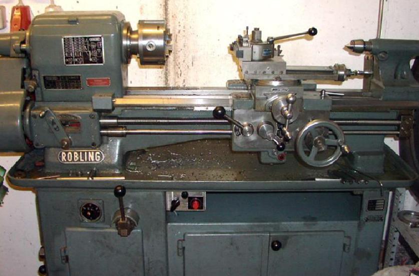
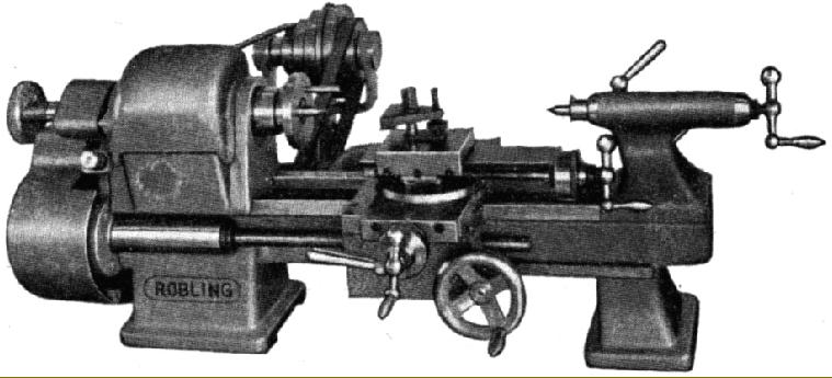
Backgeared, screwcutting, with tumble reverse and a built-on countershaft unit the Robling MB300L had an 85 mm centre height and could accept 300 m between centres. Note the overhung leadscrew. |
|
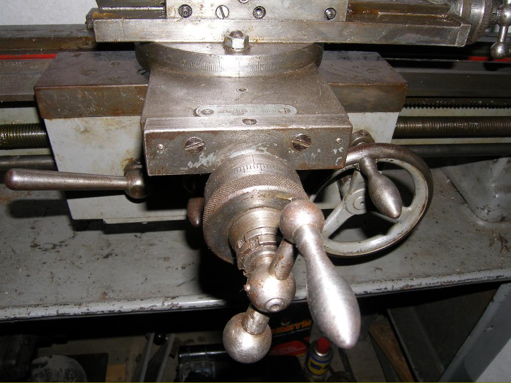
The relatively slender proportions and long travels of the elegant cross and top slides betray a previous life on one of the maker's precision plain turning lathes |

|
|
|
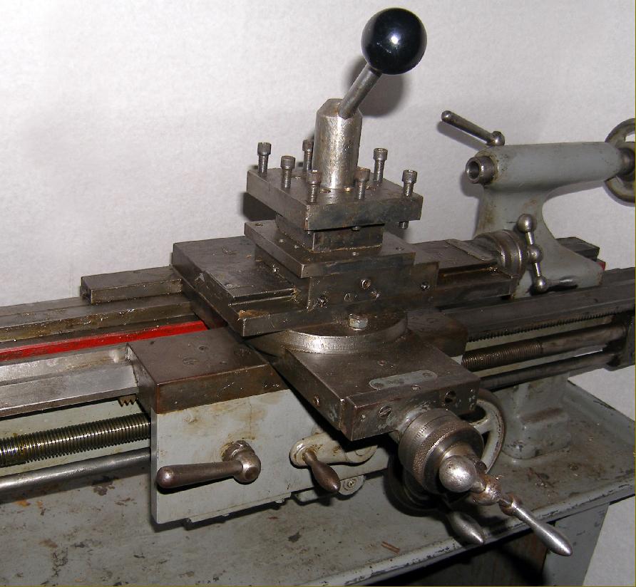
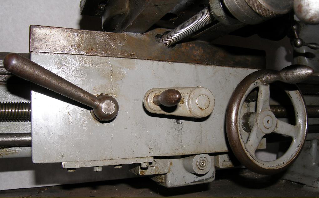
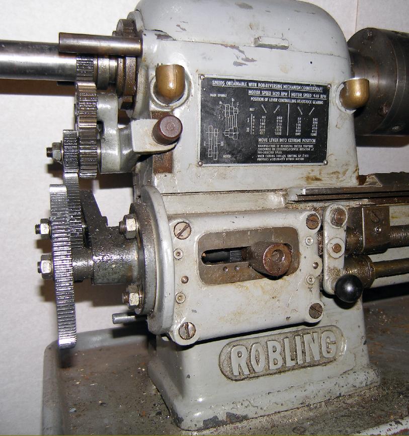
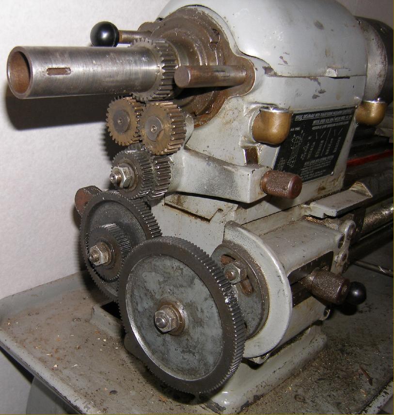
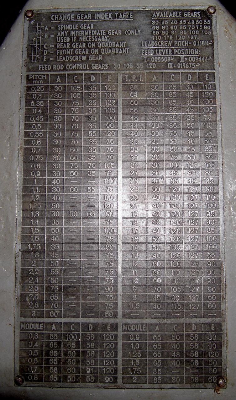
A form of simple screwcutting and power-feed gearbox was provided to give, by a lever sliding horizontally into indented positions (with a neutral between each) three ratios for every setting of the changewheels |
|
|
|
Should any reader have data about the Robling company, Home Machine Tool Archive Machine-tools Sale & Wanted |
||