|
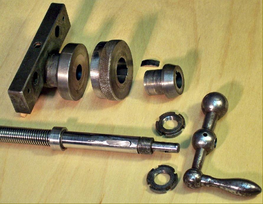
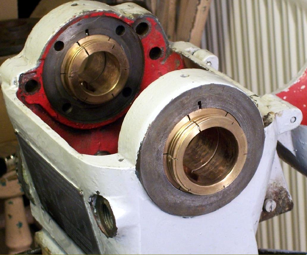
Cross and top slides screws turned with an exceptional smoothness and it might have been expected that the unit contained a ball-thrust bearing. It didn't. The effect was produced only by the precise fit and superb surface finishes of the components |
|
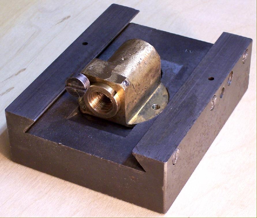
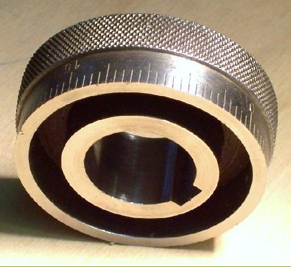
The "two-part" slide-feed bronze nut where one half of the thread was cut into a cylinder that could be adjusted backwards and forwards within the main nut to eliminate backlash |
||
|
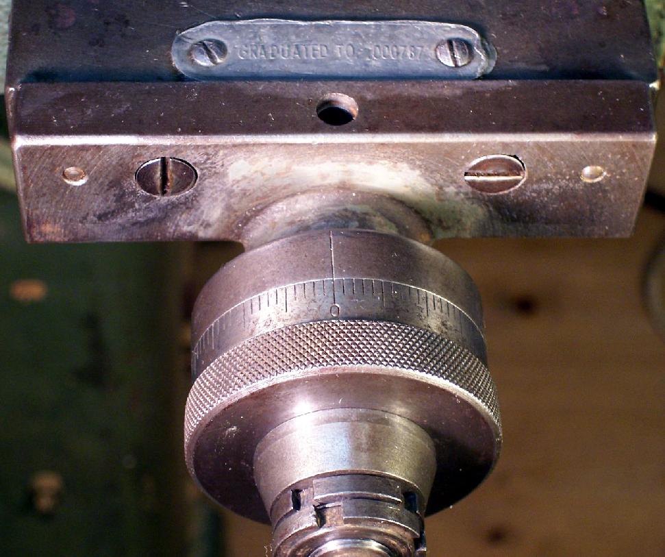
Both cross and top-slide screws were 2 mm pitch with, on export versions, a rather pointless label engraved with graduated to 0.000787 ". Even a very experienced British engineer, brought up on imperial measurements and completely familiar with them, would have found it difficult to visualise 0.000787 ". On the other hand, if the dial had been left with metric graduations where the small divisions represented 0.02 mm and the larger ones 0.1 mm (engraved 0, 05, 15, etc.) a single division of 0.02 mm would have been easy, it being just a gnat's whisker under a thou. At least Robling were being honest for some German lathes exported to "inch" countries are known to have retained metric feed -screws and nuts on the compound slide - but fitted with dials engraved with imperial graduations. |
|
|
|
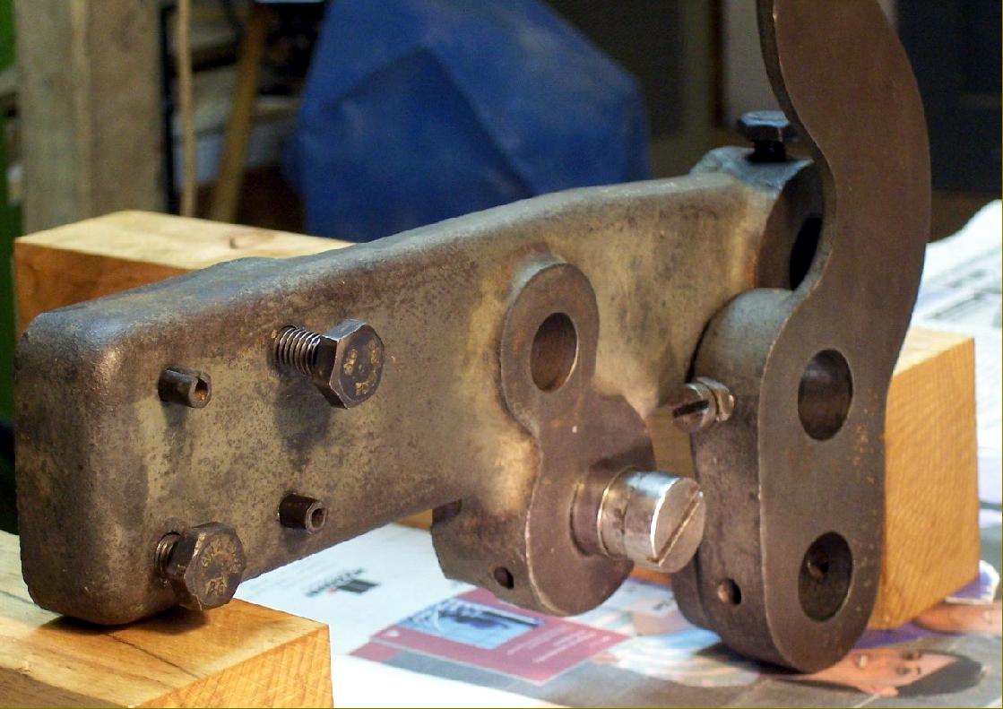
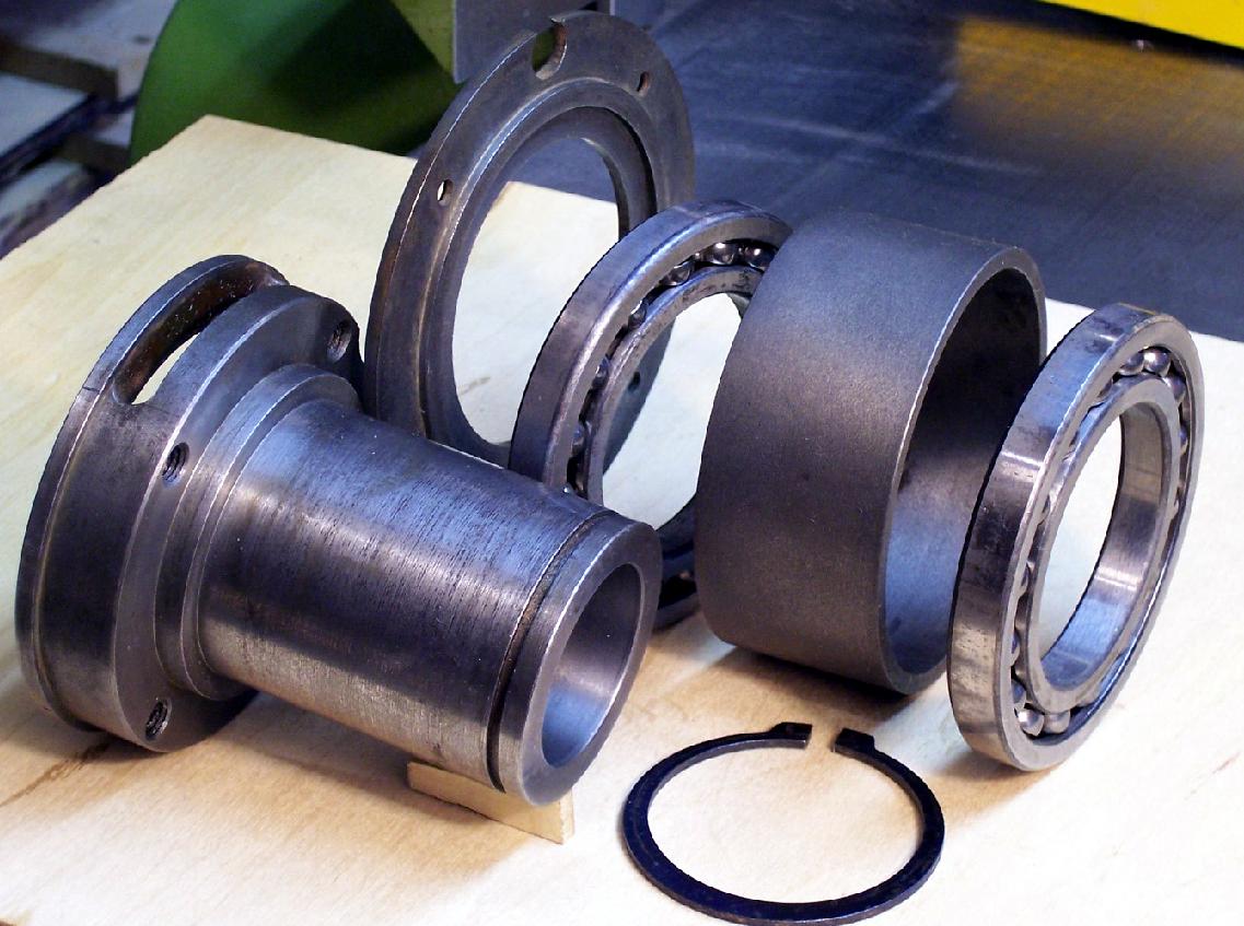
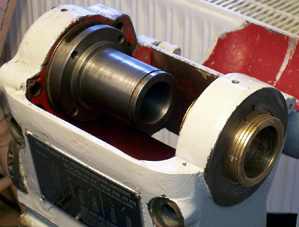
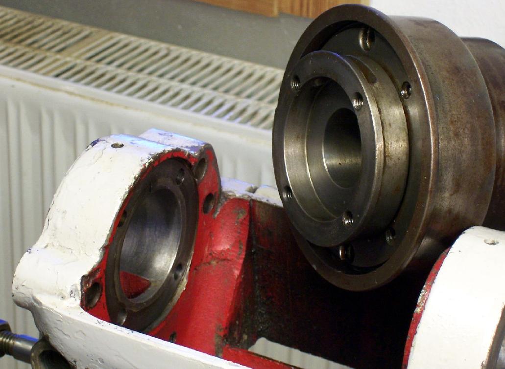
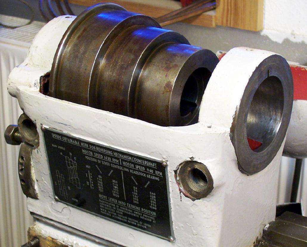
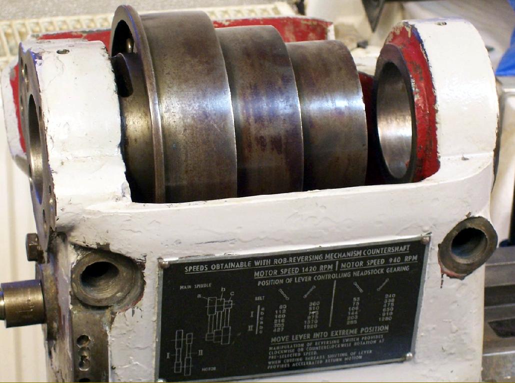
To prevent belt pull from overloading the spindle bearings, the pulley ran (like those of many similar precision lathes) in its own ball races supported on a sleeve bolted to the inside face of the headstock |
|
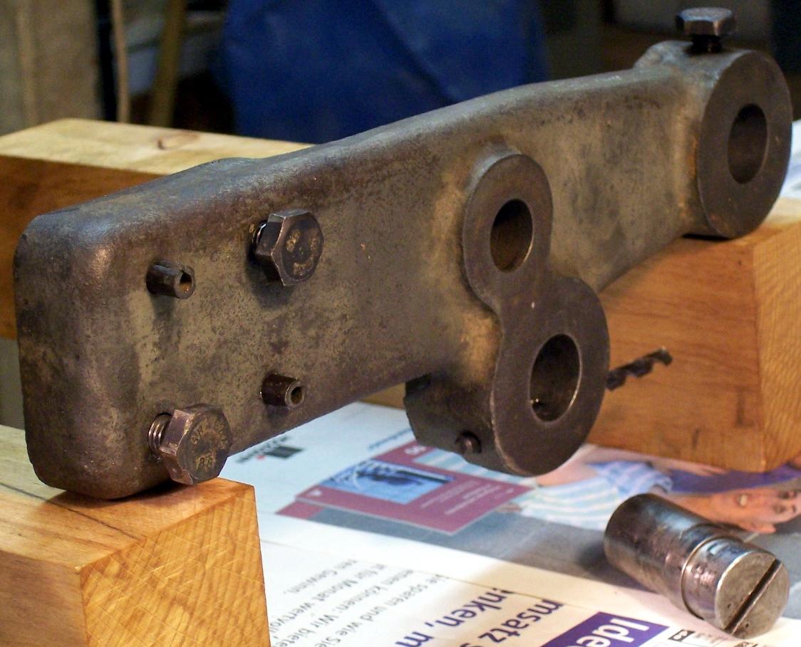
Bearings assembled in the headstock. Note the hole through the headstock's rear face: this allowed a 12 mm rod to pass into one of two holes (set 180 apart in the end face of the pulley) to lock the assembly for a change of spindle-nose fitting |
|
|
|
|
|
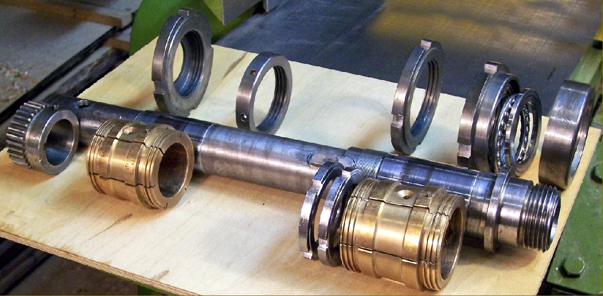
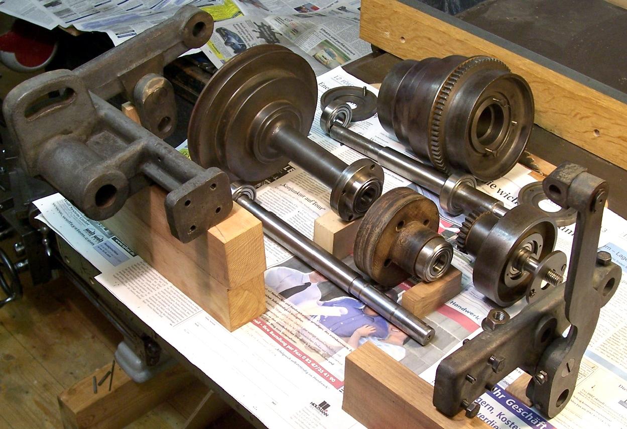
Robling drive unit. An "exploded view of the complete unit. The swing arm on the right moves the drive shaft - with the V-belt pulleys and the friction wheels - from the high to slow speed position . On the left side of the frame is the pivoted support for the pulley end of the drive shaft . The friction wheels are screwed to the casting that connects with the pulleys and are supported by two ball bearings .The friction wheels are made of Tufnol ( or a similar material ) as is the sprocket that drives the large gear wheel when slow spindle speeds are engaged. The use of a Tufnol-like material was probably for noise reduction. A clever touch was the provision of a fine adjustment for the setting of the friction wheels in relation to the metal rings , against which they work . The pivot, on which the swing arm (carrying the drive shaft ) rotates , is turned slightly off-centre and, with a slot in its end, can be adjusted in-situ to a precise setting. |
|
|