|
Continued:
Raglan"Five-Inch"
Called simply the "Five-inch", the final production Raglan lathe had a rather prosaic title for what was, undoubtedly, the Company's finest-ever (and rather expensive), product. In 1966 the basic model was listed at just under £300 but, mounted on the cabinet stand (£36 : 15s : 0d) and with a screwcutting gearbox (£37 : 16s : 0d) a 5-inch 3-jaw Burnerd chuck (£16 : 1s : 9d) and a faceplate (£4 : 11 : 6d) this rose to just short of £400. To put that figure in perspective a Myford Super 7, to the same specification, was a few pennies under £200 - with the take-home salary of a newly qualified teacher that year being just £55 a month.
Even though they looked rather different, the headstock and bed of the 5-inch were dimensionally identical to the earlier models - as was the mechanical, variable-speed drive system that, on the standard machine, could rotate the 11/32" bore Timken taper-roller bearing spindle at speeds between 38 and 1750. Again, as with earlier versions, a "High-Speed Spindle" model could be specially ordered with a top speed of 2500 rpm; however, model omitted the screwcutting facility and the power feeds were driven by V belts and "pick off gears" rather than the screwcutting gear train and power-shaft combination of the standard lathe.
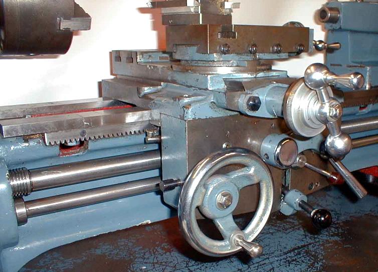
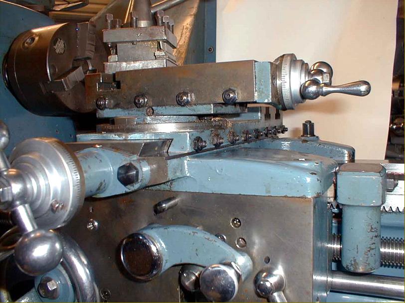
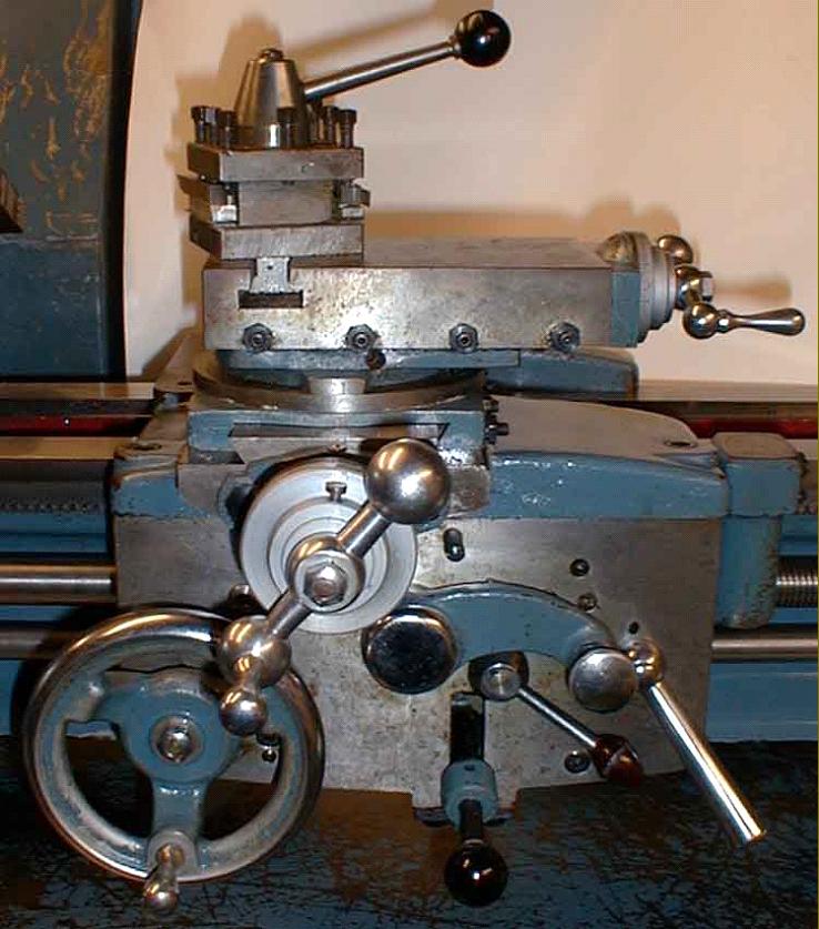
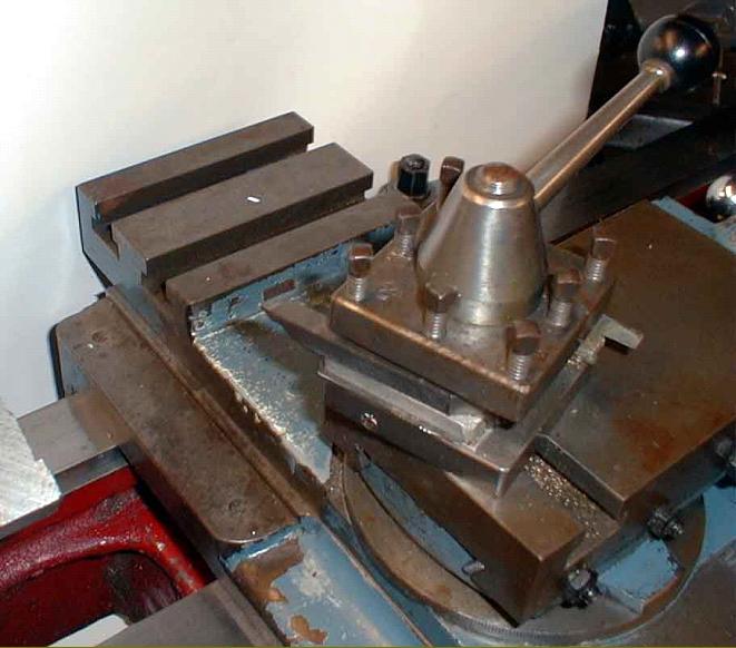
Major modifications to the 5-inch that significantly improved the lathe concerned the screwcutting arrangements, saddle, apron and compound slide. An interesting point concerned the new cross slide that, while much wider than that on the Little John, was significantly shorter than the ways on which it ran - the reason being the need to accommodate a taper-turning unit. Of the latter attachment there were two types, the earlier being an almost exact copy of that used on the Atlas 10-inch and the later one of Raglan's own design carries on twin bars.
Over time the short cross slide caused the ways to wear more in the middle than the ends; however, if the optional, full-length slide with a T-slotted section at its rear was used, the difficulty vanished and wear was both slower and more evenly distributed (though using the T-slotted slide precluded the fitting of a taper-turning attachment). Very early versions of the 5-inch had shorter cross slide ways, the subsequent 1-inch increase in length (as found on the vast majority of examples) being obtained by cantilevering the out the front of the saddle casting. The rack-pinion gear was, initially, carried over from the little john but this weak point (the teeth eventually snap off) was replaced by a stronger unit with a larger gear on a shaft with its end section increased in diameter. Another useful change on the 5-inch was to the cross-feed screw and nut where both were significantly increased in size to give a much better feel and a greatly extended service life.
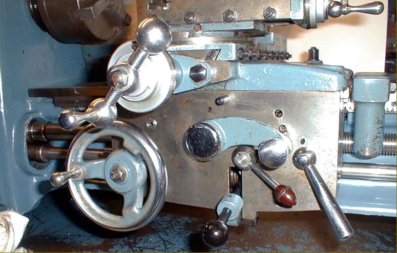
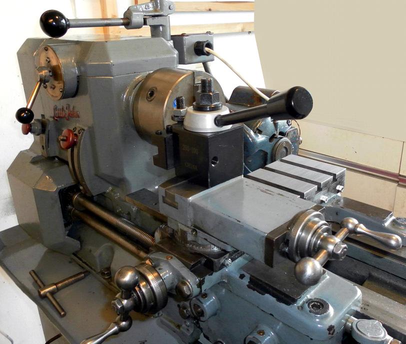
Completely redesigned and significantly improved, the apron had the carriage handwheel moved to the left-hand end and a quadrant arm on its face that moved into three indented positions to select neutral or power sliding or power surfacing feeds. Another lever was arranged to allow an instant release of the power feeds and a knock-off for these provided by a button on the left-hand face of the apron that was intended to be pressed by a new, bed-mounted stop. The remarkable ease with which the feeds could now be flicked into and out of engagement was at complete variance with the earlier system. However, although the great majority of the 5-inch lathes were fitted with the new parts, a number have been discovered with the earlier apron (with a slide-and-lift lever to engage power feeds), from the Little John. These lathes would almost certainly have been offered at a reduced price to training establishments and schools, for each so far discovered has also lacked a screwcutting gearbox. Unfortunately, as the headstock end of the bed used on the "5-inch" used a different casting when fitted with a screwcutting gearbox it is not possible (unless serious machining is undertaken) to retrofit the changewheel model.
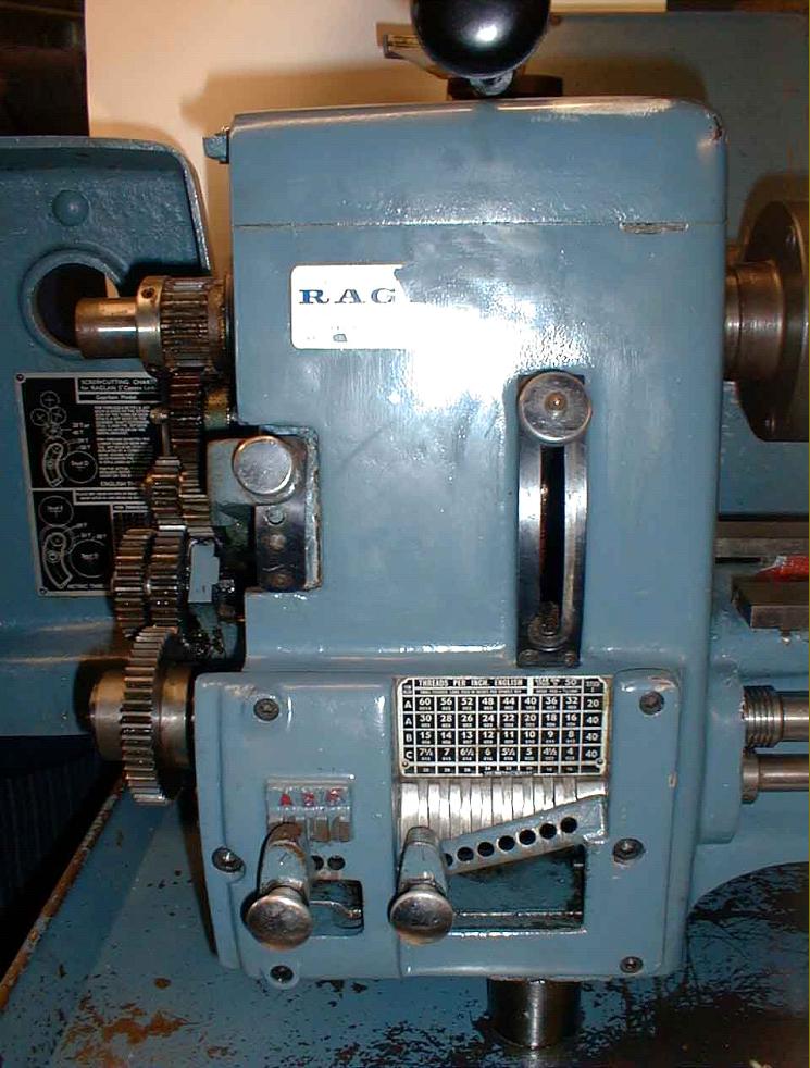
Rounded off to give it a more contemporary appearance, the headstock was much the same as before though a few machines were sold with an American long-nose taper L00 spindle fitting (as used on, for example, Harrison "Eleven Inch" and some "L5A" models) while a similar number appear to have been fitted with a rev. counter built into the headstock casting. Headstock bearings (Timken outer 16284B and Timken inner 16150) were identical left and right but the rear had a bronze sleeve to bring it down to the shaft diameter. Stronger changewheels were covered by a properly hinged guard (with a catch to hold it closed instead of the simple lift-off cover on the Mk. 2) and mounted on an easily adjusted bracket.
With lots of filler used on the castings, the lathe was particularly well finished and much preparation and care went into the painting. As a result, many have survived in their maker's enamel finish with only minor cosmetic blemishes - a Raglan 5-inch in fine condition is an impressive sight (and should also perform as well as it looks). Although most 5-inch models were finished in blue others, the writer has seen others, obviously ex-factory, in green and a plumy red - with others reported in grey and tan. Although the familiar blue seems to have changed in shade over the years, the following code will give something very close to the original: BS381C No 636 PRU Blue.
All "Five-inch" models appear to have been supplied on cabinet stands; although strongly constructed on two girder-section steel beams (and rather handsome in outline) the early versions were strange affairs that lacked a chip tray and with the switchgear mounted inconveniently and dangerously on a panel at the tailstock end of the bed - however, both these little design foibles are, of course, easily corrected. The stand used during the last years of production was based on a modified Myford Industrial Cabinet fitted with a larger chip tray and the lathe carried on simple raiser blocks made from steel bar.
Final Models
Assembled under the ownership of Myford, the last of the Raglan lathes can be recognised by the use of that Company's traditional "fully-machined" and chemically-blacked nuts and bolts - and the modified Industrial Stand mentioned previously. An interesting change was also made to the drive system on some machines; because the variable-speed drive pulley was mounted on the motor shaft, and needed to be an exact distance from its matching pulley under the headstock, it was necessary to use a particular make and model of electric motor. In Myford's modification a shaft, carried on a pair of simple plumber-block bearing assemblies and with the variable-speed pulley mounted on one end, replaced the motor. At the other end of the assembly was an ordinary V-pulley, driven by the motor positioned lower down on the back of the stand. This freed the makers (and subsequent owners) from the restrictions of a single-make motor, for it was now possible to use one of almost any shape or size - providing, of course, that it was of a suitable rating. This modification can be made, with great advantage, to earlier machines, especially when the original motor fails - or if a conversion is to be made from three to single-phase electrics. When considering the size of single-phase motor to use, do bear in mind the relatively high transmissions losses inherent in the variable-speed drive system; the lack of "capacitor start" on many modern motors means that a larger one might be necessary to start the lathe than to run it at top speed and, finally, the fact that a slightly over-size motor will have an easier and longer life than one that has to struggle for a living. Around 1 h.p. power should be correct but, for safety's sake, it would be unwise to go above 1.5 hp. Interestingly, Raglan themselves offered an accessory similar to the device just described; however, they rather mysteriously called it the Single-pulley drive attachment designed to: fit in place of motor when electric power is not available. Perhaps they envisaged it being driven by a separate power source, a stationary engine, water wheel or windmill, perhaps?
Adaptations
An interesting conversion of the "Five-Inch" lathe was the Labomill "Combination" or "Universal" machine manufactured by Antony H. Croucher of Holybourne, in Hampshire. This could turn, line bore and horizontal mill and undertake both surface and cylindrical grinding.
Personal Notes on the Raglan Factory - by John Stevenson
I started work at the Raglan factory in early 1969, and left about the end of that year. I was employed to build the aprons and screw-cutting gearboxes. The Company had recently been bought by Myford - and were to subsequently close it around 1971. The factory, an old three-story Victorian lace mill, was on Raleigh Street, in Nottingham. The machine shop was on the ground floor, the main fitting shop on the first floor (with the spray shop) while the second floor was used for stores and the assembly of millers, capstan lathes and the plain-turning "Loughborough" training lathe. The top floor was in the attic area and consisted of the fettling shop where all the casting came by way of an old lift. I don't know where the main castings were done, but they came in "aged" and part-finished in as much as the main bed ways had been rough machined. Finish machining was carried out on a large horizontal miller with a ganged-cutter set-up. A lot of the other operations were performed on a couple of large lathes with box jigs bolted to faceplates. As I didn't work in the machine shop I cannot, unfortunately, remark on many of the operations nor make of machine tool employed.
Most of the factory's equipment was very old and no investment had been made for many years. A particular machine I did study as being of interest was the one that made the leadscrews. I believe that this was made within the works, but I am not sure. It looked to be based on an old centre lathe but was equipped with two leadscrews, one right hand, one left hand. One was geared to give the correct pitch of 8 t.p.i the other geared up to give a course pitch of 1 or 2 t.p.i. The leadscrew was set up in a collet chuck and supported by the tailstock and two travelling steadies; the first cut was put on and the machine started. At end of its travel the tool was retracted and the leadscrew gearing changed over so that the carriage returned at high speed - whence a new cut was applied and the process repeated. All the operations were automatic and activated by cams and ratchets. When leadscrews came off the machine they were bent like a banana due to the stresses being relieved; they were straightened by being supported on V-blocks and pressed under an arbor press. This machine made also made the cross and top-slide screws - with dummy screws made in threes, tapered in stages, fluted, hardened and then used as taps for the cross and top slide nuts.
Bedways were made from hardened-and-ground steel strips, with blind tapped holes in their bases threaded to carry studs that held the rails to the bed. The bed castings were finished by carefully hand-scraping the way locations using a dummy bed as a surface plate. I cannot comment on the building of the headstocks, as I wasn't involved with them at all - but I can remember a jig being used for setting the thrust bearings on the variable-speed drive. The saddle and apron assembly was straightforward and all the bearing faces were scraped in as matching pairs. The swivel markings on the top-slide and the tailstock barrel ruler graduations were both rolled in with hardened circular dies.
Built along traditional Norton "quick-change" lines the screwcutting box employed unhardened, machine-cut gears. The boxes were '"run in" on a dummy machine, the process entailing the mechanic holding the selector lever hard into mesh to bed-in any unevenness, followed by a thorough wash out and a re-oil. This dummy machine was interesting: it was a brand-new Raglan lathe that had been dropped while being loaded and had snapped off just in front of the chuck. The decision was taken not to rebuild it, but to give it to the fitters as a machine for polishing shafts/bushes to obtain a precision fit. During the time I was with the Company the build list consisted of centre lathes, a couple of capstans, some training lathes - but no millers.
The spray shop was also on the first floor and run by two guys who were responsible for all the preparation and final paintwork, the machines being painted only when they were finished and signed off. The rough castings were prepared with a thick filler paint made by a Company called Trimite (who are still in existence http://www.trimite.com/). The first coat was literally trowelled on, the second coat applied by a paint brush and then, as it became skin dry, repainted with cellulose thinners. This had the effect of 'melting' the topcoat and allowed it to flow to a smoother finish. The job was given overnight to dry and then rubbed down with wet-and-dry paper. Two more coats were then applied by spraying, with a light sanding between. The finish consisted of one base coat and two topcoats of a special cellulose-based paint, again by Trimite, a product also supplied to Myfords - the finish was thus first-class and far superior to that on competitors' machines. The works manager when I was there was a wonderful man, the highly-respected Mr. Gibbs, who had come from Myford Engineering, the new owners..
|
|

