|
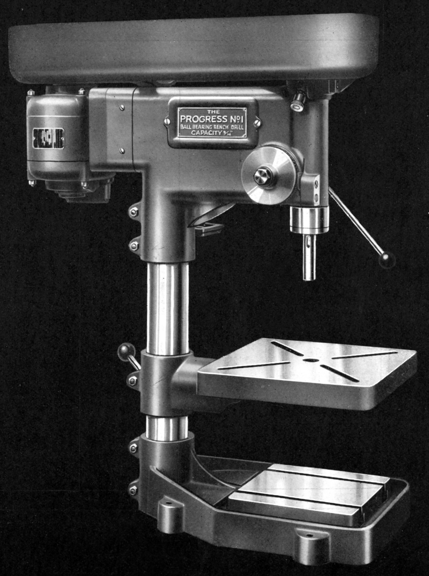
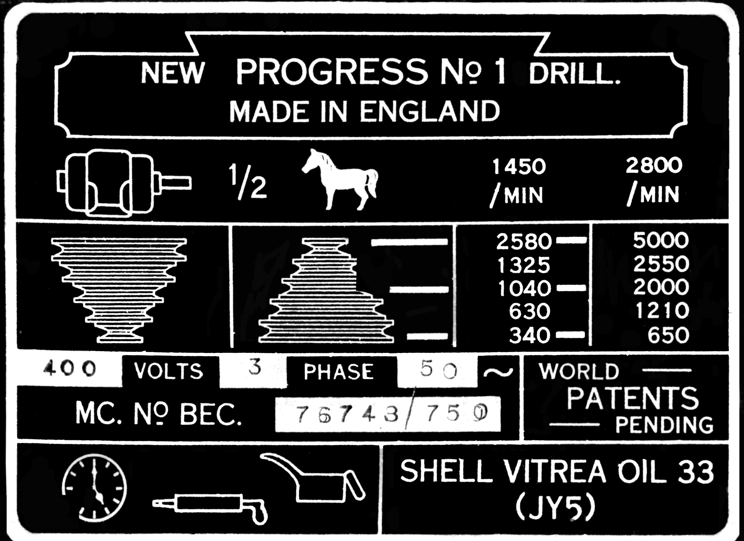
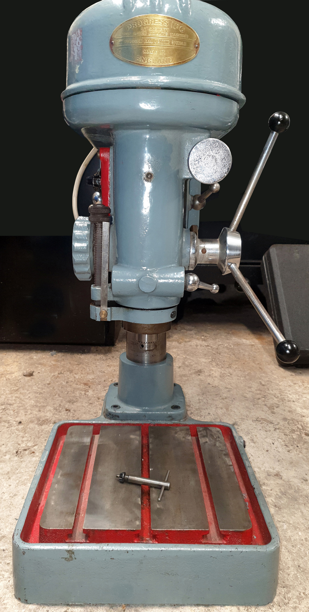
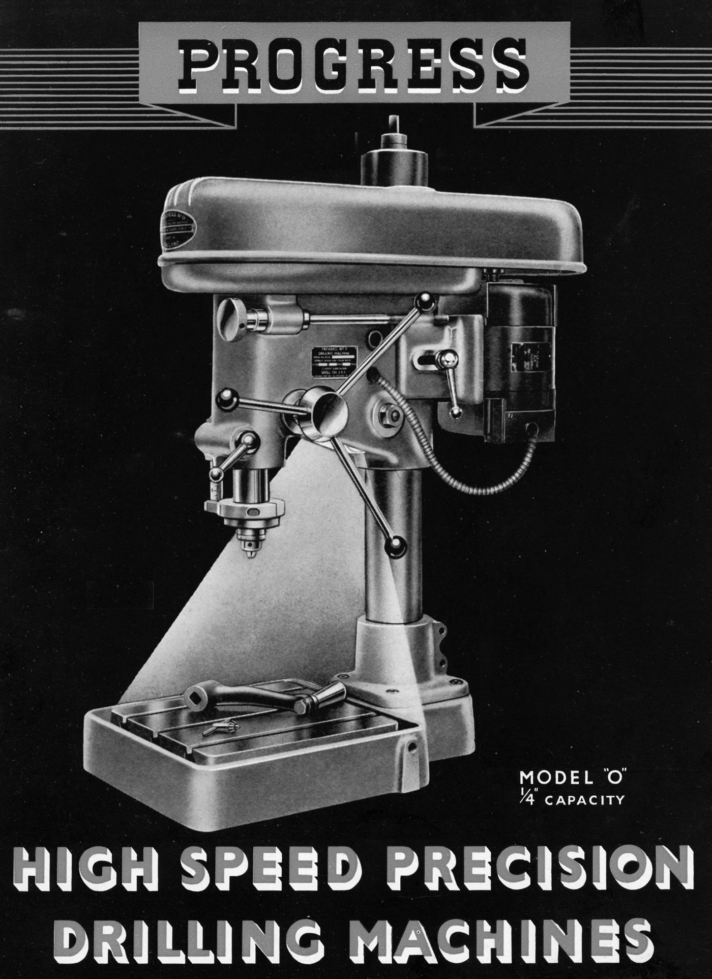
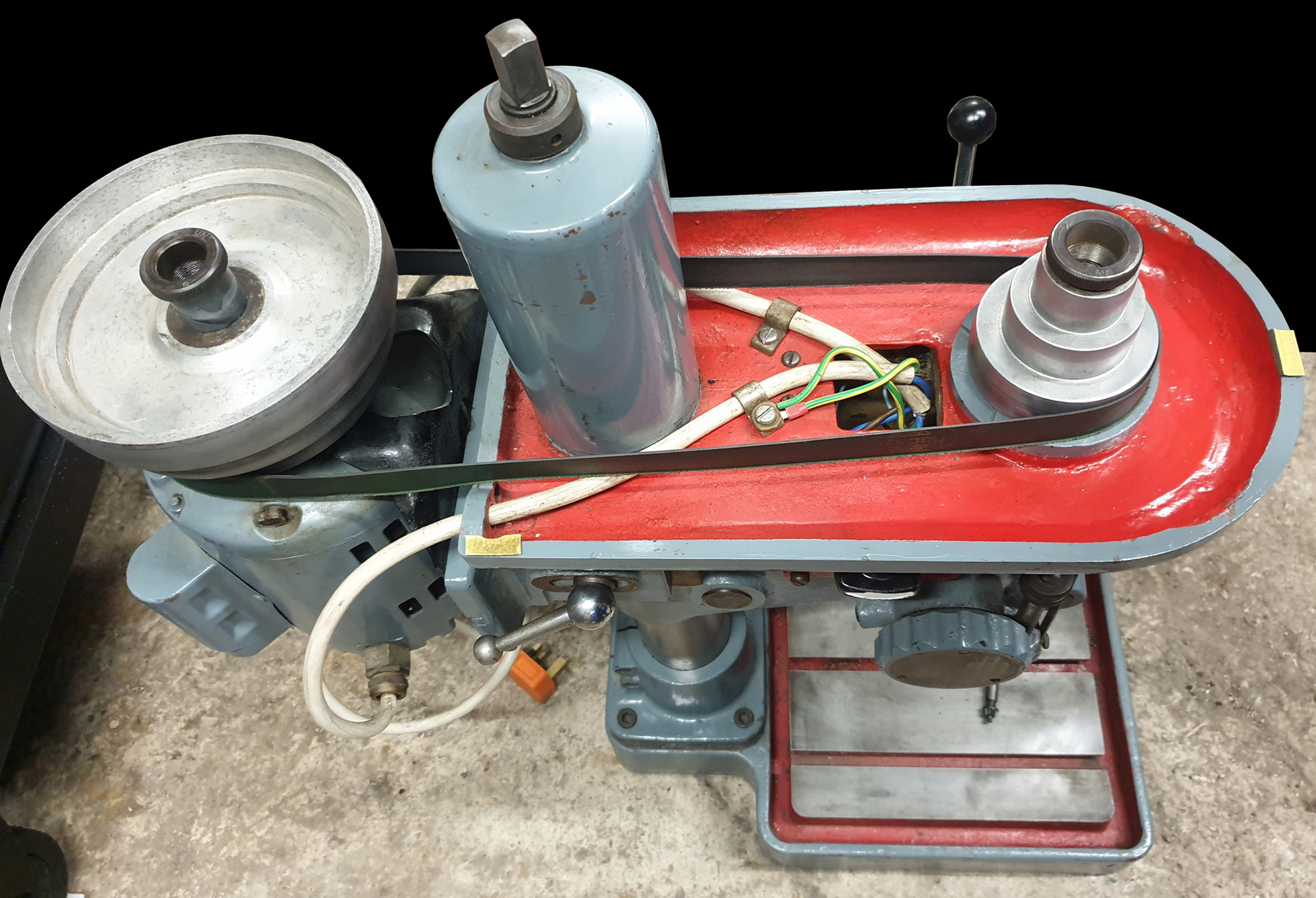
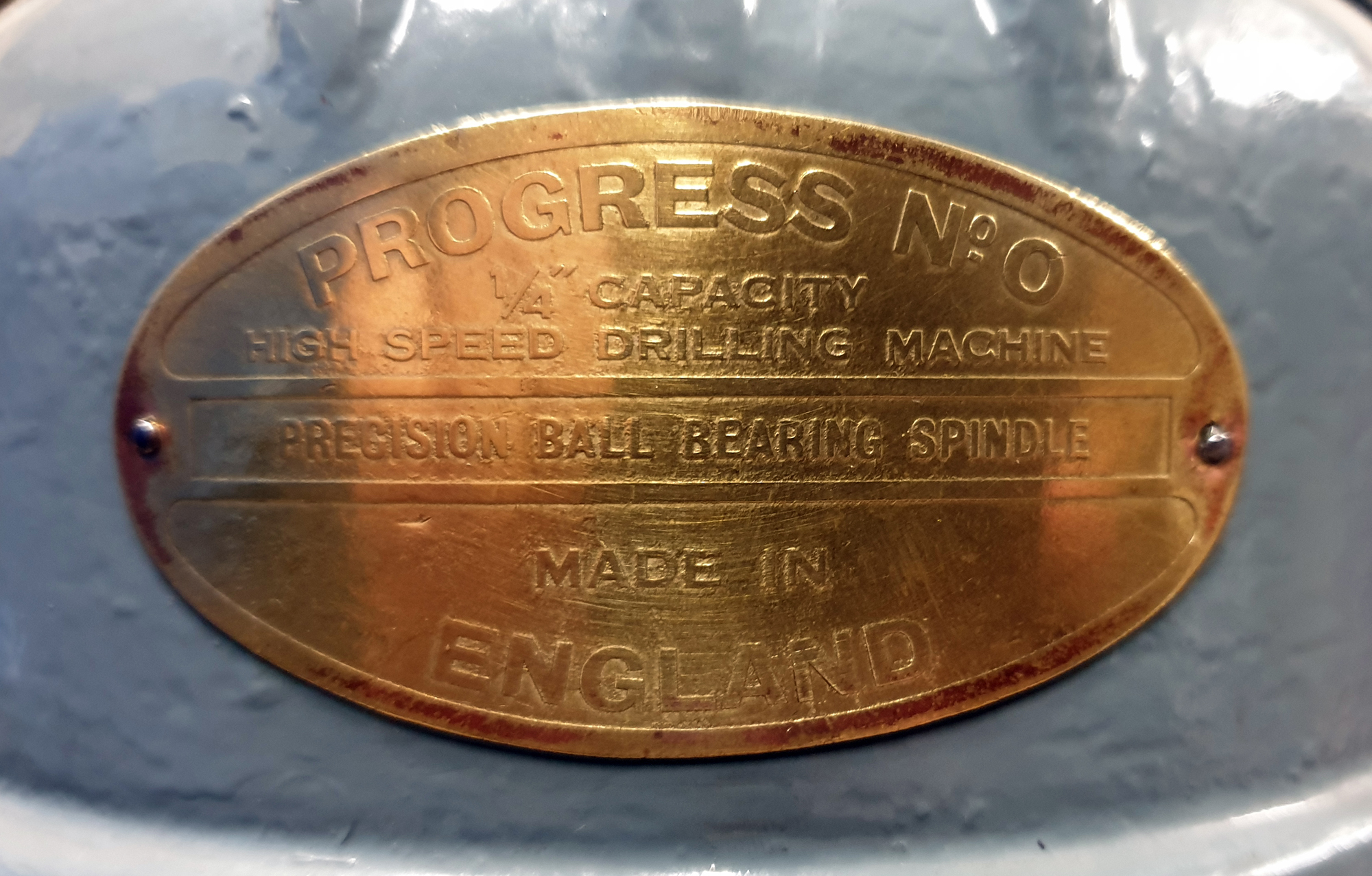
Introduced, it is believed, in 1946, the Progress No. 1 bench and No. 1 S pillar drills were to be built in two distinct versions, the Mk. 1 and very different Mk. 2. However, although the sales literature only lists the two basic types, over the years a number of small changes were made to the drills (many insignificant and so undocumented in the manual) and various badges affixed that read, for example, "New Progress No. 1" or just "Progress No. 1" Hopefully, the following will explain - if not entirely - how they developed. In addition, a smaller drill, the lovely little 1/4" capacity, high-speed Model 0 was also introduced at around the same time - though this may have been as late as 1949. The drill had a very heavy, 9.5-inch square T-slotted base and, because it lacked a separate elevating table, the head (mounted on a 2.75-inch diameter column of ground-finished steel) was fitted with a screw-operated elevation mechanism and handle (identical in arrangement to the similar model by Flott). Held down by large, knurled-edged ring screws, the balanced, 3-step flat-belt drive pulleys could be quickly swapped over from spindle to motor to give a total of six speeds that spanned 650 to 12,000 r.p.m. (though this very high speed might have involved the use of a 2-speed 3-phase motor).
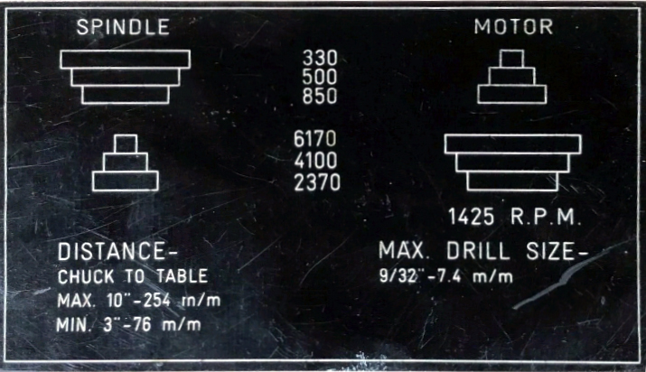
However, not all the No.1 Progress drills had this very wide speed range, some being found marked with a much slower speed range from 330 to 2370 r.p.m. Mounted at the back on a cast-iron plate, the motor had a very neat and quick-to-use arrangement for altering the belt tension, a screwed rod, fitted with a knob at the front, being arranged to push or pull the assembly forwards and backwards.
Made from a 3% nickel steel with a case-hardened and ground nose, the 2.75-inch travel spindle ran in two deep-group precision class ball races - belt pull being eliminated by the driven pulley being support in its own pair of ball races. Made from a .4 carbon steel, the quill was machined with the usual rack on its back and its depth ruler engraved with English and metric scales. As the drill was intended for finer than normal work a light was provided, this being built into the main body between the quill and column.
Mk. 1 Progress Models 1 and 1S
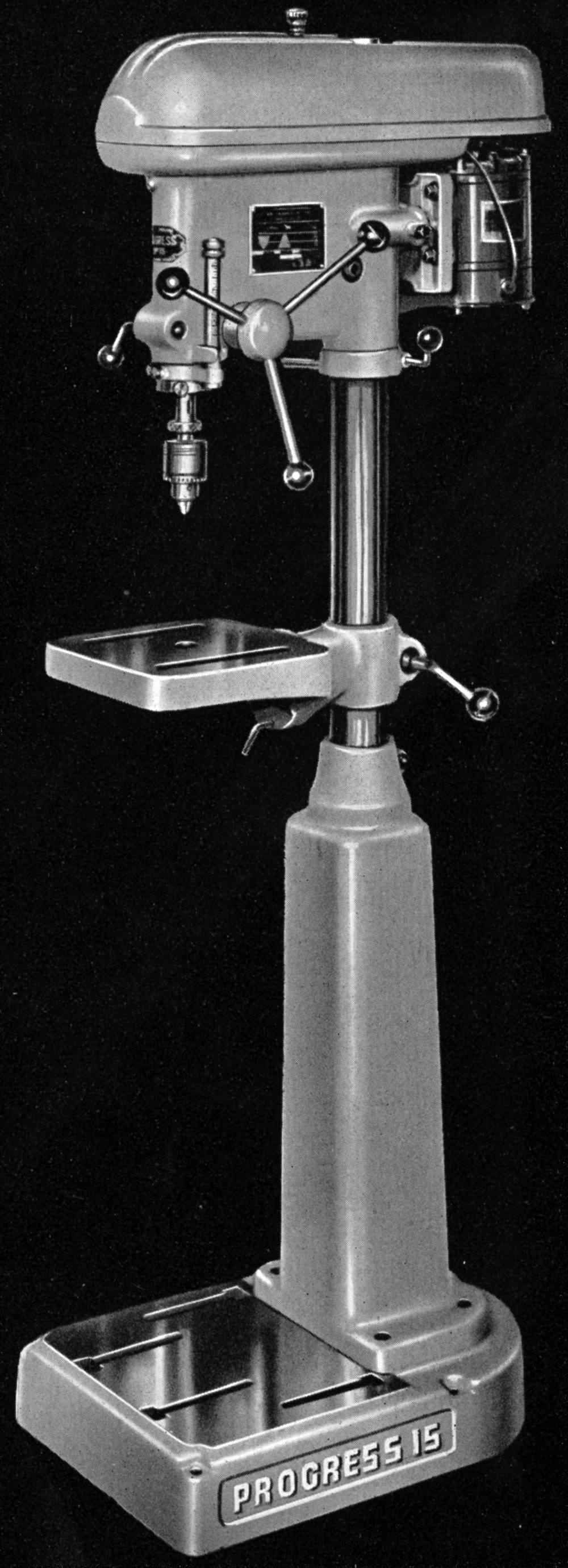
Reflecting the latest design ideas, the Mk. 1 had a modern appearance that would not look out of place today - and radically different from other contemporary manufacturers whose machines still resembled those made during the 1930s (to see how drill design and styling changed, look at the pages displaying the many models made by the Atlas Press Company from the early 1930s until the 1950s). Constructed from iron castings and built around a solid steel column 2.75 inches in diameter, the main body of the Progress Mk. 1 was a rigid, rectangular box of clean lines that dropped over the top of the column - it could not be adjusted up and down - and locked in place by two clamp bolts closing up a split in the back of the casting. Other departures from traditional design including the drill being supplied complete, in a ready-to-run state fitted with a 0.5 h.p. 3-phase or single-phase 1400 r.p.m. motor, wiring and switchgear; its 5-step all-V-belt drive was guarded by a full-length enclosure in sheet steel; a 3-handle capstan wheel was fitted to drive the quill through its 3 inches of travel (though there was no quill lock); a built-in light was fitted beneath the head and the large drum that held the quill return spring engraved with a drilling-depth scale - though there was no positive vertical stop, as on many competing machines, to pre-set a limit to the quill's travel.
Unfortunately, even though described as "medium-priced" and "capable of handling all types of work within its capacity" it was fitted with a frustratingly inadequate No. 1 Morse taper spindle. Even worse was that, instead of the Morse taper being built into the spindle, it was formed on the inside of a three-inch extension that stuck out beyond the end of the quill - so reducing the available depth between the nose and table top. Fitted with the largest ordinary No. 1 Morse taper shank drill, the maximum capacity in resilient material was limited to 9/16" - though no doubt with a drill chuck fitted, and a strong arm applied to the lever, a little more could have been accomplished before the taper slipped and was ruined. Used within their limits - and operated by those familiar with their intended purpose - No. 1 Morse taper drills are fine, but, installed to cope with general-workshop jobs, a mistake; more suitable models would include ones with reduction gearing in the head, examples being the Progress 2G or one of the Meddings Pacera M-Series. Confirming that the maker's intention that this was a drill intended for lighter work, the five spindle speeds spanned 850 to 5000 r.p.m. The moveable table was a useful 11" x 11" - the maximum clearance to the bare spindle nose being 14 inches - and the base (of the bench type only) machined with a 7" x 7" working surface area and two T-slots (the foot of the pillar model was left plain).
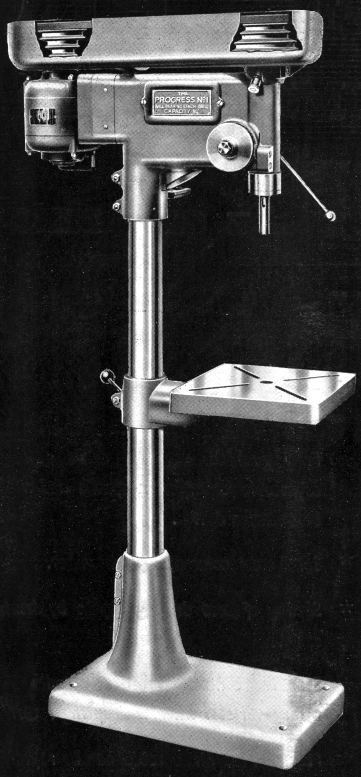
Unlike a number of lighter pillar drills on the market, the Mk. 1 Progress had a long vertical extension of the cast-iron base into which the steel column socketed. However, the writer is sure that he remembers a version where this was not fitted and, with the base very light in construction, the drill needed bolting to the floor before it could be used.
Standing 33.5" high the No. 1 Progress bench drill in its Mk. 1 form stood 33.5 inches high and weighed, with motor, 150 lbs. - the pillar model was 70 inches tall and weighed, for its type, a rather slender 176 lbs.
Mk. 2 Progress Models 1 Bench and 1S Pillar
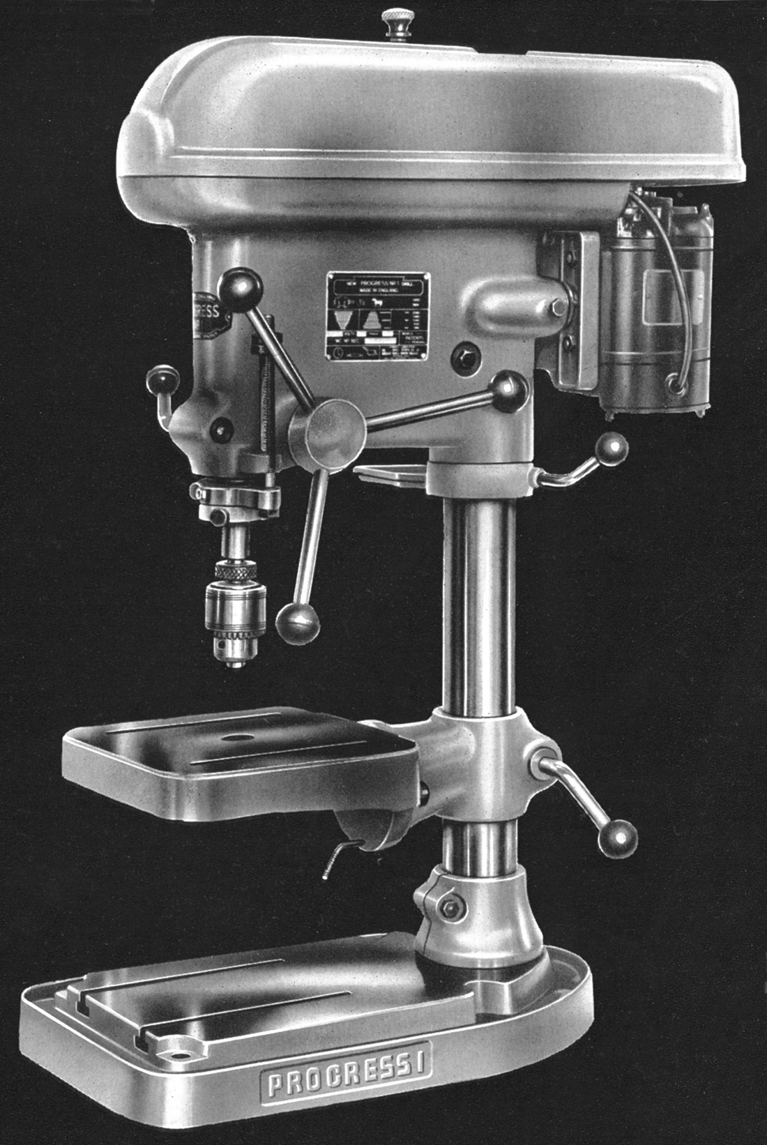
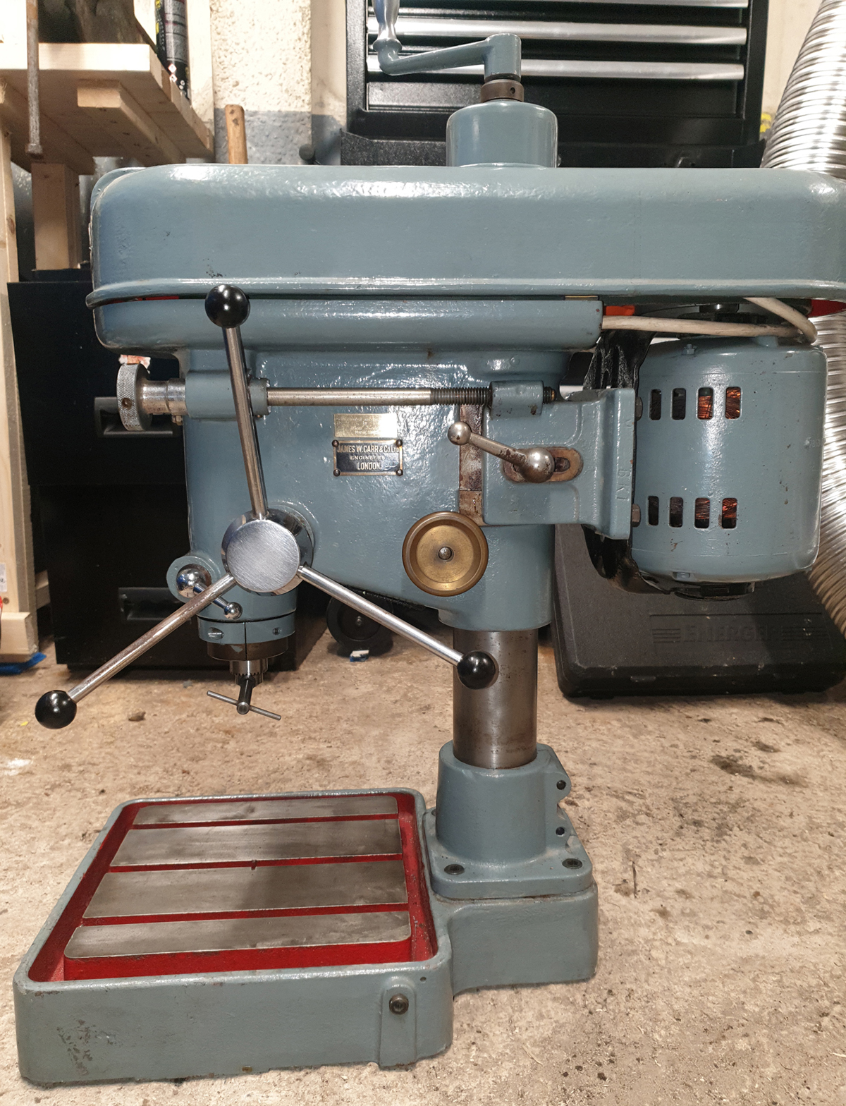
Built in early and late versions, the Mk. 2 Progress No. 1 was quite different to the Mk. 1 and much more thoroughly thought out as to the details of its design. It too could be had in both bench and floor-standing models, the latter being built massive foot, machined with four T-slots, and at first equipped with a bolt-on cast-iron pillar into which the upper, 2.75-inch diameter steel column holding the head was socketed (all steel column parts on all versions of the Mk. 2 were precision ground). Later the option was offered of a long plain column, this allowing a greater variety of jobs to be tacked as the heads could now be moved up and down through a far greater range than before.
Early and late models of both versions appear to have differed significantly only in their table size, the former being 11" x 11" with just two parallel slots and the latter 13" x 13" with eight - four disposed radially and one set in line with each side. In addition, the column bracket to which it was affixed was beefed-up and increased in length.
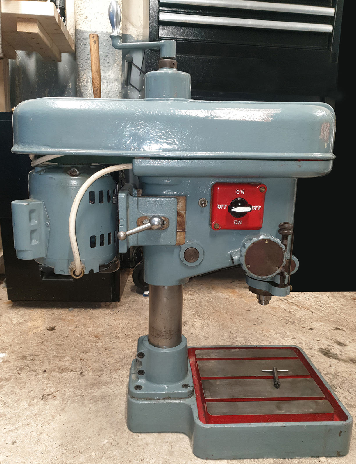
The head, unlike that on the No. 1 Mk. 1, could be adjusted up and down the column, a swivelling tool tray being clamped around the column beneath it to act as a stop (the arrangement making adjustment easier and safer) while the head-to-column clamp was a powerful, and easy to operate "split-barrel" type. Drive came from a standard-fit rear-mounted 1/2 h.p. 1400 r.p.m. single or three-phase motor bolted to a plate with twin bars that slid into holes bored in the back of the head. Sliding the head backwards and forwards adjusted the tension of the A-section V-belt - but, as there was no quick-release mechanism to slacken it when changes of speed were required, the only solution, apart from having to slacken the bolts that locked the bars in place, was to set the belt so that it both drove efficiently for ordinary jobs while being slack enough to be run over into the next groove - a setting that is surprisingly easy to find. Although it was a fuss to adjust the belt tension, the pressed steel belt guard on some example was fitted with a spring-assisted release, the operating mechanism being triggered by a small toggle lever on the right-hand face of the head casting or, later, by manipulating the knob on top of the cover; closing the guard meant just pushing down until it locked automatically. Electrical switchgear was built in, a rotary switch being provided on the left-hand face of the head.
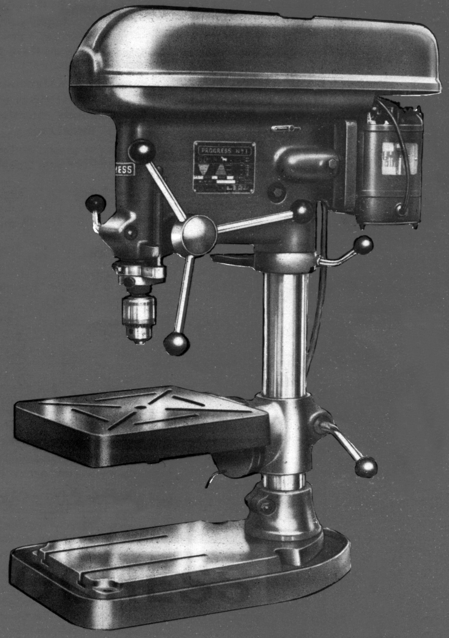
Dynamically balanced, both drive and driven pulleys were in a die-cast aluminium, the five speeds provided as standard spanning 40 to 2580 r.p.m. - though the option was listed of a 2800 r.p.m. motor that gave a range more suited to drilling small holes of 780 to 6160 r.p.m. However, some drills have been found with plates showing spindle speeds of 340 to 2580 r.p.m. for a 1400 r.p.m. motor and 650 to 5000 r.p.m. with one running at 2800 r.p.m.
In addition to the usual pair of deep-groove ball raves, the 4-inch travel spindle was equipped with a separate thrust race and - possibly uniquely - its nose formed with both a Jacobs No. 6 taper to mount a drill chuck and, in a short extension, a No. 1 Morse taper with a knock-out slot. However, on later 8-slot table machines this unusual arrangement was dropped and just the Jacobs taper provided. Quill travel was operated by a 3-handle capstan wheel, the return spring able to be adjusted as to its tension and a powerful lock, of the same type that held the head in place, fitted to secure the quill at any desired position (unlike many cheaper drills where locks simply closed up slots in the various castings - with the eventual risk of fracture - on the Progress No. 1 Mk. 2 all were of the "split-barrel" type that clamped without distortion by drawing together the two halves of cylinders -their ends formed to wrap around the cylindrical element).
At last on a Progress, a proper adjustable vertical-arranged, drilling depth-stop-cum ruler was fitted, the usual two knurled-edge rings nuts being provided to lock the setting. On the early version of the bench drill the maximum clearance between the nose of the drill chuck and the table was 10 inches - and to the base 17 inches. Unfortunately, the later model had a much-reduced capacity: just 6.5 inches from chuck nose to the table and 15.5 inches to the base. The first version of the pillar drill with the cast-iron column support had a clearance from chuck nose to table top of 15.5 inches - and to the base of 46 inches. However, the later model of this type also suffered a capacity reduction, the drill-chuck-to-table clearance losing three inches and from the chuck to the base four inches - the long plain column model, of course, being unaffected.
Net weight of both early and late bench drills was approximately 252 lbs (152 kg) and the pillar version 322 lbs (146 kg). The bench drill was around 39 inches high and 13 inches wide; the pillar versions 69 inches tall and the base 15 inches wide.
Some pictures are high resolution and may take time to load
|
|