 |
|
|
|
|
|
|
|
|
|
|
|
|
|
|
|
|
|
|
|
|
|
|
|
|
|
|
|
|
|
|
|
|
|
|
|
|
|
|
|
|
|
|
|
|
|
|
|
|
|
|
|
|
|
|
|
|
|
|
|
|
|
|
|
|
|
|
|
|
|
|
|
|
|
|
|
|
|
|
|
|
|
|
|
|
|
|
|
|
|
|
|
|
|
|
|
|
|
|
|
|
|
|
|
|
|
|
|
|
|
|
|
|
|
|
|
|
|
|
|
|
|
|
|
|
|
|
|
|
|
|
|
|
|
|
|
|
|
|
|
|
|
|
|
|
|
|
|
|
|
|
|
|
|
|
|
|
|
|
|
|
|
|
|
|
|
|
|
|
|
|
|
|
|
|
|
|
|
|
email: tony@lathes.co.uk
Home Machine Tool Archive Machine-tools for Sale & Wanted
Machine Tool Manuals Machine Tool Catalogues Belts
Books Accessories
Myford ML7 LATHE
Myford ML7 Photo Essay
Myford Home Page Detailed Myford 7 Series Article Tri-lever ML7
ML7 Serial Numbers Rodney Milling Attachment
ML7 Lathes New in the Box Amolco Milling Attachment ML7R
ML7 Capstan Accessories ML7 Rebuild
A complete data pack on the ML7 is available here
and a dedicated book on all Series 7 lathes here
This is a "summary and photographic" page: for a detailed description of the Myford ML7 and other Myford Series 7 and Series 10 models, click here for the Myford home page. An interesting article about rebuilding an ML7 here and a photo essay about the ML7 here. Occasionally unused ML7 lathes are discovered, two entirely original ones are shown on this page and another lower down this page.
When it was unveiled in August, 1946 (at £34, without a motor) the Myford ML7 lathe was greeted with astonishment. Designed by Ted Barrs during the closing years of WW2 (1939-1945), here was a well-designed, compact lathe with a neatly built-on motor-countershaft unit, fully guarded belts and changewheels - and with a specification guaranteed to delight any model engineer who had struggled with the inadequate machines offered by a host of under-capitalised, smaller English machine-tool makers in the pre-war years. The concept was not, however, new for the same kind of integrated design had been introduced as long ago as 1932 in the form of the 9-inch Atlas (developed into the long-lived 10-inch model), and the neat little "6-inch" first made in 1937.
An immediate sales success in both Britain and overseas - when exports were vital to the country's prosperity following WW2 - many British customers, with an ex-Services gratuity burning a hole in their pocket had to wait until vital export orders were fulfilled - the cry of the day being, "Export or Die" - and waiting lists ran to over 12 months. The lathe continued in production until 1979 and, because the design was so right to begin with, only very minor changes in specification were made over the years with the same design of cross and top slide units surviving until the late 1990s on the Super 7 based ML7R model.
All Myford ML7 lathes included a K prefix in their serial number (other designations include the ML.5 Capstan lathe as the "F", the M.U. capstan as the "G", the M.L.6 capstan as "H" and the Myford/Drummond M-Type as "J").
The ML7R was not based on the ML7 but on the Super 7 - the model being created by leaving off the spindle clutch and fitting the less expensive cross and top slides from the ordinary ML7.
A detailed description of the Myford ML7, and other Myford Series 7 and 10 models, can be found here, an interesting article about rebuilding an ML7 here and a photo essay about the ML7 here.
A number of copies of the ML7 have been found, some quite dreadful but also including a rather fine one, shown at the bottom of the page, by the Italian firm Minganti.
Some pictures are high resolution and may take time to load
|
|
|
|
|
|
|
|
 |
|
|
|
|
Badge used on the spindle belt guard cover on all ML7 lathes
|
|
|
|
|
|
|
|
|
|
|
|
|
|
|
|
 |
|
|
|
|
|
|
|
|
1947 - and the Myford publicity department produced this sectional drawing. For a very high-resolution download (39MB) that you can copy to an pen-drive and have printed out in colour on an A2 sheet by your local graphics shop, click on the picture or here (be patient, it takes time…)
|
|
|
|
|
|
|
|
|
 |
|
|
|
|
|
|
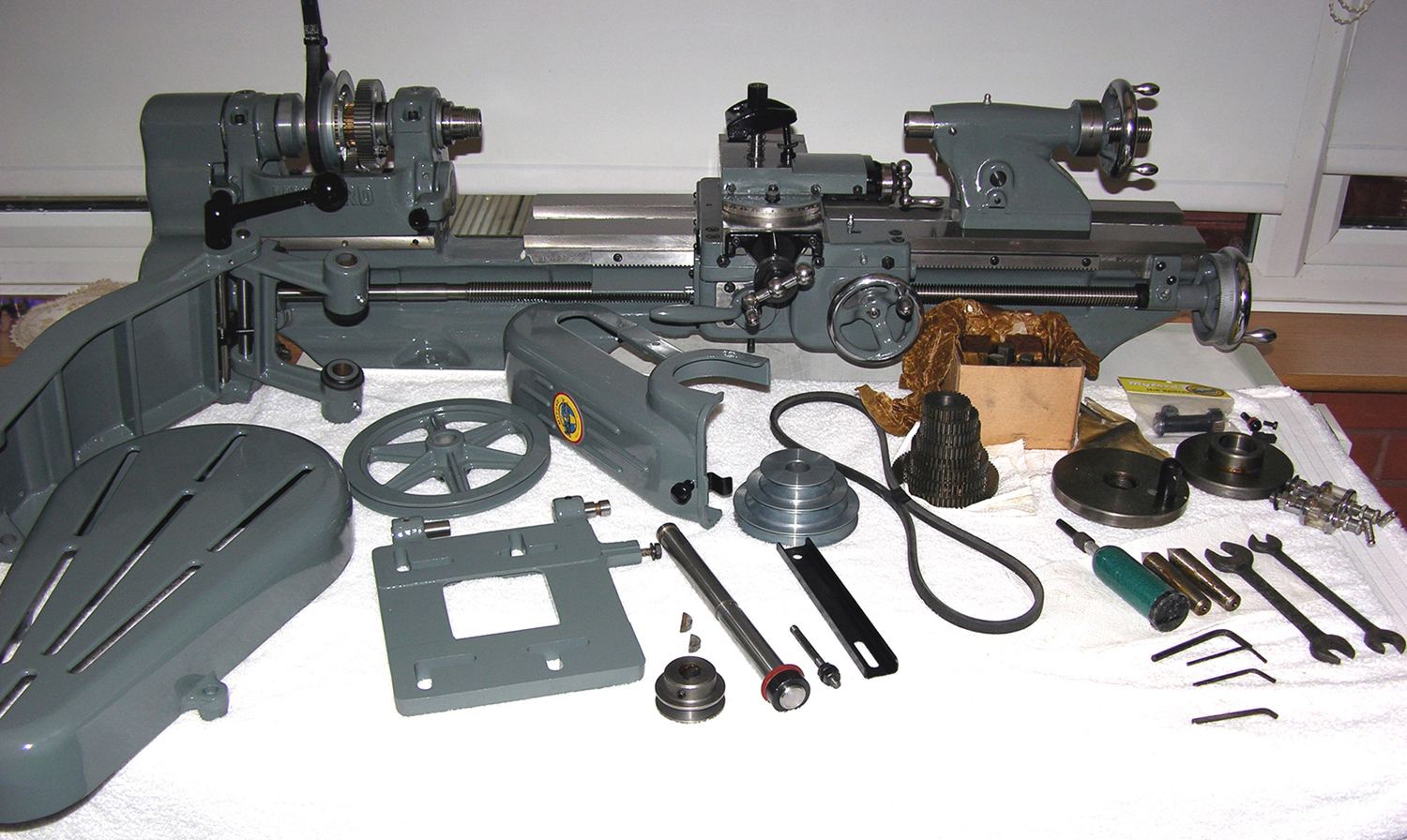
Discovered unused in 2012, this ML7 is shown as delivered to the customer and requiring basic assembly. Another two examples, in original finishes, can be seen
|
|
|
|
|
|
|
|
|
|
|
|
|
 |
|
|
|
|
|
|
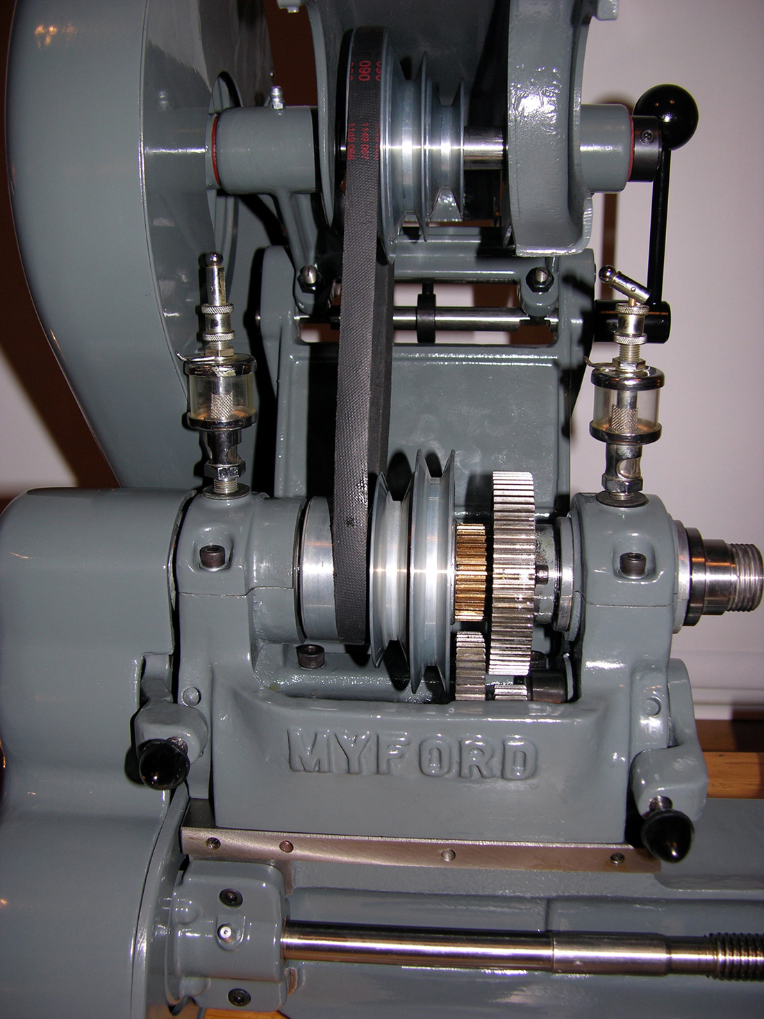
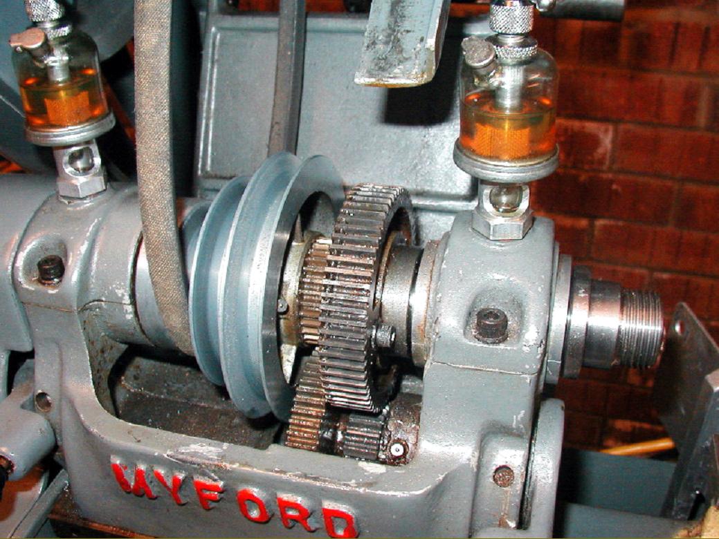
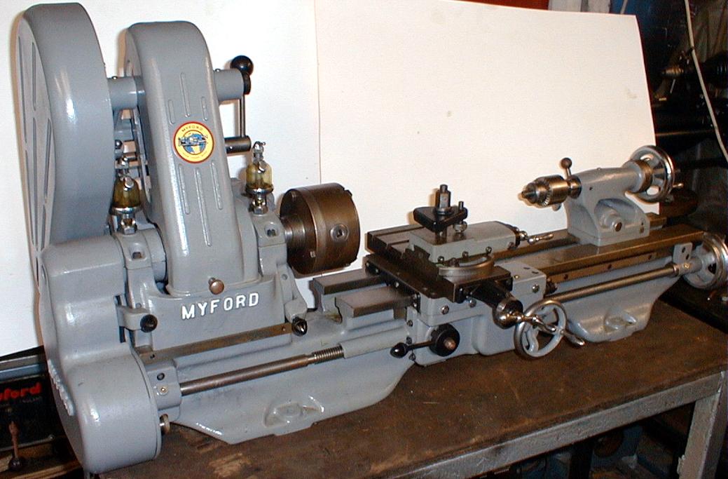
An unused ML7, found in its crate during 2012. The original paint having deteriorated in storage, the owner repainted in Myford colours. The only non-original point is that the Myford name on the headstock would have been picked out in cream paint. Are the oilers original? They might be replacements for the ones normally supplied by "Adams Lube Tech"
|
|
|
|
|
|
|
 |
|
|
|
|
|
|
|
|
|
|
 |
|
|
|
|
|
|
|
|
|
|
 |
|
|
|
|
|
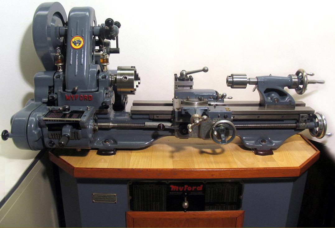
Standard ML7
3.5" centre height and 20" between centres, backgeared and screwcutting.
|
|
|
|
|
 |
|
|
|
|
|
|
Pride of ownership - a restored Myford ML7B with spindle clutch - the B suffice indicating a screwcutting gearbox
|
|
|
|
|
|
|
|
|
|
|
|
 |
|
|
|
|
|
|
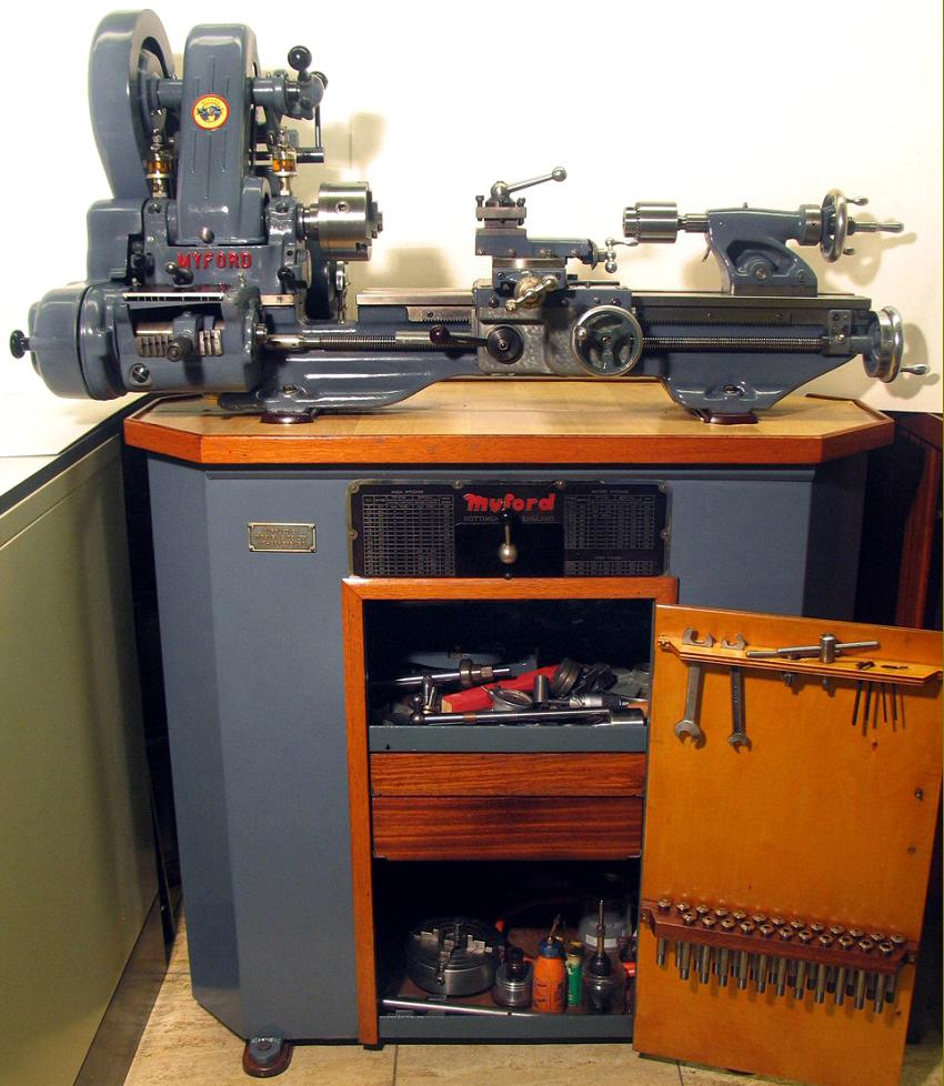
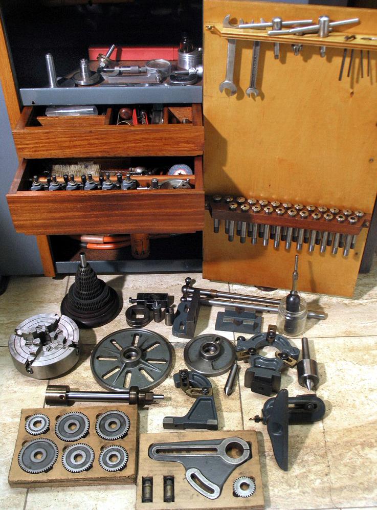
The ordinary maker's stand lack a door and collet storage - deficiencies
easily overcome by many enthusiastic owners
|
|
|
|
|
|
|
 |
|
|
|
|
|
Useful accessories: in the foreground a screwcutting metric conversion set
and, left towards the back, the Burnerd half-depth body 6-inch 4-jaw chuck
|
|
|
|
|
|
|
 |
|
|
|
|
|
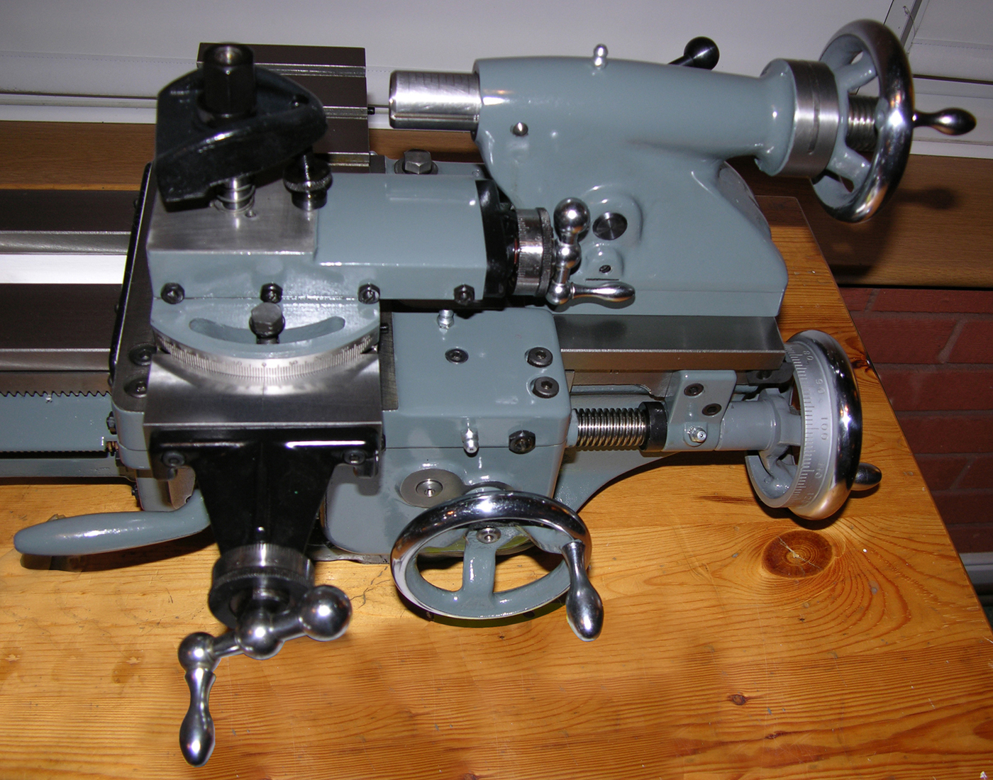
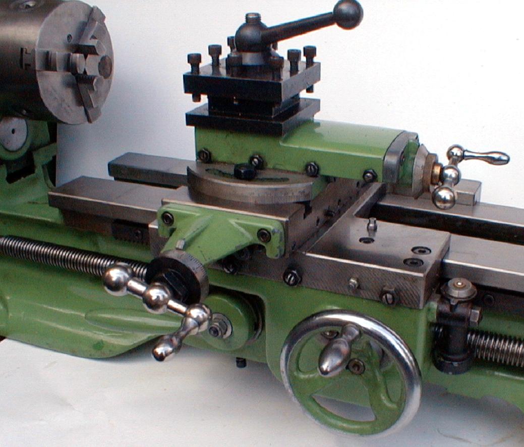
Carriage assembly clearly showing the extended bridge casting on the end of the cross slide that gave a useful increase in travel; this was of special benefit when using a vertical milling slide. The micrometer dial fitted is the later machined and engraved type.
|
|
|
|
|
|
|
|
|
|
|
|
|
 |
|
|
 |
|
|
|
|
|
|
|
|
|
|
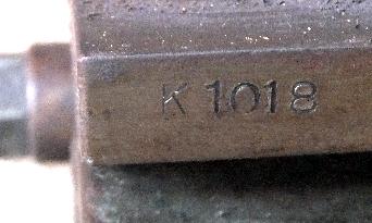
ML7 bed numbers started at 1001, so this is the 183-third. machine made. The number can be found stamped at the tailstock-end of the bed, on the rear vertical shear. If a letter "R" is present, this indicated a bed that has been reground at the Myford factory
|
|
|
|
|
|
|
|
|
|
 |
|
|
|
|
|
|
|
|
|
Even earlier - the 16th ML7
|
|
|
|
|
|
|
|
|
|
|
|
Standard ML7 headstock detail
|
|
|
|
|
 |
|
 |
|
|
|
|
|
ML7 drive system with rubber-bushed, "resilient-mount" motor - which is by far the best type to use.
|
|
|
|
|
|
|
|
|
Countershaft drive unit from a very early ML7.
The cut-out sections in the upright were filled in on later models and the full length hinge pin through the base of the motor platform changed to two short studs.
|
|
|
|
|
|
|
|
|
|
|
|
|
|
|
 |
|
|
|
|
|
Clutch equipped ML7 with changewheel cover removed and belt guard lifted
|
|
|
|
|
 |
|
|
|
|
|
|
Rodney Vertical Milling attachment. Clamped to the bed, the drive was taken to the miller from a No. 2 Morse taper plug in the headstock via. a flexible coupling. A drilling quill and fine down-feed were fitted and the nose of the miller was fitted with a standard Myford spindle nose thread. A smaller, simpler version was also produced without the quick-action drill feed.
|
|
|
|
|
|
|
 |
|
|
|
|
|
|
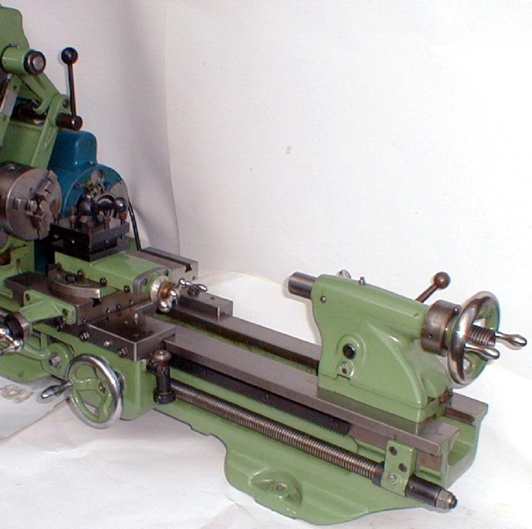
An ML7 converted for production work and fitted with a lever-operated collet chuck, cross slide mounted turret attachment and a cut-off slide. Visible just behind the bed is the top part of a multi-stop unit, used to provide a dead-length stop to the saddle movement. Besides the items illustrated, a much larger bed-mounted capstan unit was available with built-in stops and auto indexing. Some lathes were sold ready converted for production work with the screwcutting gear, compound slides and tailstock removed - and sometimes fitted with the Tri-Leva spindle speed selector and a two-speed motor.
|
|
|
|
|
|
|
|
|
|
|
|
|
 |
|
|
|
|
|
|
Myford C7 Capstan. An early standard-production version (identifiable by the screw-feed cut-off slide) fitted with a Tri-leva spindle speed selector, standard bed-mounted capstan head, coolant unit and two-speed electric motor.
|
|
|
|
|
|
|
|
|
|
 |
|
 |
|
|
|
|
|
|
Early headstock-bearing oiler - replaced by transparent drip-feed oilers in the late 1940s
|
|
|
|
|
|
|
|
|
The lovely "Acorn" knob fitted to the tumble reverse and backgear levers
|
|
|
|
|
|
|
|
|
|
|
|
|
|
|
 |
|
|
|
|
 |
|
|
|
|
 |
|
|
|
|
|
|
|
|
|
|
|
 |
|
|
|
|
 |
|
|
|
|
|
|
|
|
|
 |
|
|
|
|
|
|
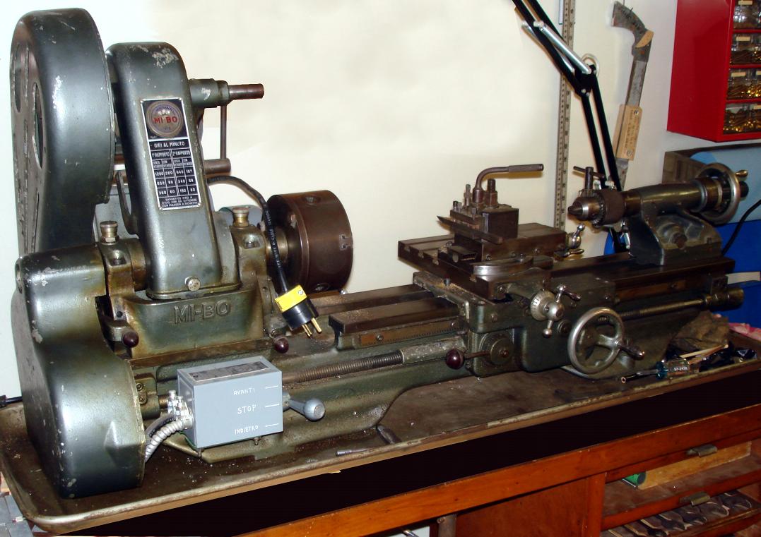
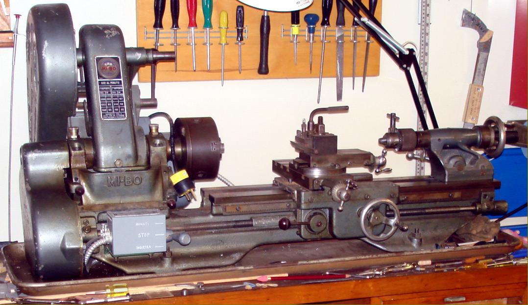
Branded as a MI-BO (cast into the front face of the headstock) this Italian-made Minganti Myford ML7 copy was discovered in Canada (unlike the better-known Taiwanese copies, one has yet to be found in the United Kingdom). At a guess it would have been made in the early 1960s, the use of the earlier "open" tailstock casting but inclusion of Super 7-like cross and top-slide handles being the clues. However, perhaps the makers had to hand an earlier example of the original ML7, the micrometer dials are of the MAKAK type, the headstock bearing are lubricated through turn-to-open wick-feed oil caps, ball-spring oilers are in evidence on slideways, tailstock and leadscrew hanger bearings and an early type curved leadscrew guard is fitted .
Minganti appear to have produced not only a very high-quality copy with smooth castings and fine detailing but, by using a double-step pulley on the motor to countershaft drive, one with 12 speeds running from 32 to 1200 r.p.m instead of the original rather slow 6 that spanned a rather slow 35 to 640). It might be that the headstock bearings were also improved with the use of bronze instead of white metal - a solution for higher speeds that was offered in later years by Myford as a replacement assembly.
If you have a Minganti-Myford the writer would be interested to hear from you
A translation from an Italian web site:
"Minganti Joseph , one of the pioneers of the Italian machine tools, was formed in his father working abroad. In 1919 he began to produce their own letter-book presses, moulds for containers cachet and a small drill press . Within a few years the business grew and moved the shop in Via della Fontanina to a new factory in Via Ferrarese .
He was always beside his wife Gilberte Gabrielli , who took charge of the organizational and accounting side of the business. At the Paris Exposition of 1928 Minganti presented the first lathe with hydraulic control and continuously variable speeds , the patents taken out giving him international fame. Then came other machine tools including drills and milling machines, as well as a number of special machines for the packing of cigarettes and production of bearings, wire mesh and, pistons. In 1936 , during the period when Italy tried to become self-sufficient in industrial production, the Company manufactured turret (capstan) lathes - models that proved to be of excellent quality and the equal of foreign ones .
During the WW2, in 1943, the factory was hit hard by a bombing raid and subsequently the German command decided to confiscate the factory's machine tools and transport them in Germany, but Minganti fought the request to obtain the transfer of the machinery and of its engineers to Palazzolo .
When her husband died during the difficult process of reconstruction and in the following decades , it was the wife Gilberte to lead the Company with intelligence and determination, qualities that were recognized with her appointment in 1964, as the first woman in Italy to be awarded the Knight of Merit of Labour.
The company moved in the early sixties in a modern industrial complex, in Via Ferrarese, and contto successfully produce machine tools, precision grinding machines, vertical lathes and automatic."
http://www.comune.bologna.it/memoriabologna/servizi/107:7100/7109/
|
|
|
|
|
|
|
 |
|
|
|
|
|
|
|
|
|
|
|
|
|
|
Mford ML7 Serial Numbers
MYFORD ML7
1001 = 1946
1090 = 1946
2045 = 1947
2510 = 1947
3112 = 1948
3520 = 1948
5105 = 1948
5608 = 1949
6849 = 1949
7005 = 1949
8992 = 1949
10550 = 1950
12762 = 1950
14067 = 1950
16879 = 1951
16903 = 1951
18447 = 1951
19900 = 1951
20600 = 1952
21894 = 1952
26323 = 1953
28906 = 1953
30989 = 1954
31592 = 1954
32045 = 1954
33200 = 1955
33607 = 1955
34103 = 1955
35670 = 1956
36002 = 1956
36167 = 1956
38115 = 1957
39100 = 1957
41393 = 1958
42203 = 1959
42820 = 1959
44781 = 1960
45012 = 1960
46203 = 1960
48165 = 1961
49002 = 1961
51232 =1962
51675 = post 1962
54013 = 1962
60200 = 1963
64987 = 1964
71006 = 1965
75138 = approx 1966
75154 = approx 1966
81275 = 1967
82989 = 1968
85000 = 1968 approx
90125 = 1969
96783 = 1970
98501 = 1970 approx
104879 = 1972
110045 = approx 1972 no factory data on that machine
114516 = Super 7 1973
115603 = 1971
118706 = 1974
121348 = 1974
|
|
|
|
|
|
|
|
|
|
|
|
|
|
|
|
|
|