 |
|
|
|
|
|
|
|
|
|
|
|
|
|
|
|
|
|
|
|
|
|
|
|
|
|
|
|
|
|
|
|
|
|
|
|
|
|
|
|
|
|
|
|
|
|
|
|
|
|
|
|
|
|
|
|
|
|
|
|
|
|
|
|
|
|
|
|
|
|
|
|
|
|
|
|
|
|
|
|
|
|
|
|
|
|
|
|
|
|
|
|
|
|
|
|
|
|
|
|
|
|
|
|
|
|
|
|
|
|
|
|
|
|
|
|
|
|
|
|
|
|
|
 |
|
|
|
|
|
|
Just occasionally, instead of the more common ML2, ML4 and M-Types that emerge from under piles of rubbish at the backs of garages, there appears one of these rather unusual and heavily-built 4-inch Myford lathes. It is thought that around five-hundred were produced during just two years of production, 1940 and 1944, with the rare advertising literature showing that Jones and Shipman, the Leicester-based grinding machine company may have had a hand in the design, production, or marketing - and could well have supplied the castings. It is known from factory records that all examples of the type carried an MF prefix, but were also listed internally as the Series E. Other forgotten or little-used factory designations include the ML.5 Capstan lathe as the "F", the M.U. capstan as the "G", the M.L.6 capstan as "H", the Myford/Drummond M-Type as "J" and the M.L. 7 as "K".
Made in late and early versions the first 4-inch - an extremely rare find - was also offered (though with a modified form of bed) as a dedicated capstan lathe. This earliest model was rather lighter than the later and had a bed that might be described as "semi-cantilever" with an enormously long foot under the headstock end (with single holding-down bolts at front and rear) and a graceful upward sweep to a perfunctory support under the tailstock. In addition there were several other minor differences: the cross-feed screw ran directly in the metal of the saddle (later machines had replaceable nuts); the tailstock used a different casting, the changewheel guard was in aluminium, not cast iron, and the tailstock-end bearing for the leadscrew was part of the bed casting instead of being bolted on.
The lathe was advertised by the makers as both the 4" -precision and "General Purpose" and was eventually made available in a Series denoted by the letter MF. The range consisted of:
MF-18.B 4" x 18" for bench mounting
MF-24.B 4" x 24" for bench mounting
MF-24.S 4" x 24" on pressed-steel stand less drive system
MF-24.M 4" x 24" with self-contained, motorised, cast-iron stand but less motor and switch gear
MF-30.B 4" x 30" for bench mounting
MF-30.S 4" x 30" on pressed steel stand less drive system
MF-30.M 4" x 24" with self-contained, motorised, cast-iron stand but less motor and switch gear
MF-36.B 4" x 36" long-bed model for bench mounting
MF-36.S 4" x 36" long-bed on pressed steel stand less drive system
MF-36.M 4" x 36" long-bed version. Self-contained and motorised cast-iron stand less motor and switch gear
Although the sales literature listed the above dimensions, internal works documents are annotated to show the actual capacity between centres was, in every case, one inch less. In addition, although the above numbers were the official listing, lathes are often found with "MF32" and "MF74" cast into the backgear guard or stamped into either the saddle or cross slide. While examples of the 24" model are relatively common, the 30-inch and 36-inch must be very rare for only one of the latter has come to light in recent years, together with a single example of an 18-inch early model.
It seems that the pressed-steel stand did not meet with universal approval for "...in response to numerous requests, we have introduced a cast iron stand which can be supplied as an extra for both the overhead countershaft and motorised stand models.." So, if you can find one on a stand in cast iron, so much the better.
Word from older Myford employees claims that the headstock of the MF32 was fitted with "pusher screws" alongside both front and rear front clamping bolts to help with alignment - but this feature has been noticed as absent from some MF32s, yet present on some MF74s; one can only deduce that the fitting must have been included only where an alignment problem occurred, or possibly as a post-production modification to help restore accuracy. Of very much heavier construction than that used on the contemporary ML2 and ML4 models, the 11-inch capacity gap bed was of deep section compared to its width and supported on robust feet, the headstock end being clamped down with four bolts.
With a 9/16" bore (some literature has this as 5/8") the headstock spindle was in a carbon steel, ground finished and fitted with a No. 2 Morse taper nose - a considerable improvement on those fitted to the ML2 and ML4. However, the spindle still ran in simple, split, bronze bearings - the type that are easily over-tightened and wrecked. The spindle nose was threaded 1.125" x 12 t.p.i. - identical to the ML7 and Super 7 - but with the "register" behind the thread set at the thread diameter. However, one machine has been found with a most unusual tapered nose - presumably designed to mount a collet holder retained by a draw tube. With an engagement mechanism unlike that of any Myford before (or since) the backgear was of conventional design, located at the back of the headstock with the spindle gears placed at each end of the drive pulley (instead of clustered at one end on other models). It was controlled, on most MF32 versions, by an over-elaborate, lever-operated mechanism that caused the shaft to slide to and fro. On all examples of the MF74 type seen by the writer the lever arrangement was omitted and a simple knob fastened to the end of the backgear shaft so that the operator could engage it as required. The spindle bullwheel was guarded by a neat cast-iron cover that hinged open to allow access to the gear-pulley coupling pin - the latter being spring loaded and with an easy-to-grip knurled edge. To ensure a positive location a stiff wire cross piece was arranged to drop into a slot cut in the face of the gear.
Continued below:
|
|
|
|
|
|
|
|
 |
|
|
|
|
|
Continued:
A choice was offered of either a 4-step V pulley - which seems to have been the standard offering - or a 3-step flat belt when the lathe was to be connected to an existing overhead line-shaft drive. Spindle speeds with the V-belt drive ranged from 27 through 45, 68, 109, 165, 268, 420 to 650 rpm with the drive countershaft and its motor platform being one of several types: a remote version, fastened to the bench behind the headstock (very like that offered for the ML2/4 with a swing-head but of heavier construction); another bolted to the back of the bed with an over-centre lever for tension whilst the third version (but only encountered on two machines so far) used a heavy casting mounted on the back of the bed in such a way that it could be adjusted vertically. Its upper section, carrying the pulleys, was arranged to pivot under the control of a screw-adjusted rod that passed through the bed from front to back with the screw-adjustment handwheel, on the front face of the bed, adapted from that used on the tailstock of the ML1 to ML4 Models. Drive from motor-to-countershaft was either by either single or double A-section V-belts. A wire mesh guard, of a design not unlike that also fitted to the Myford/Drummond "M-Type", was fitted over the motor-to-countershaft belt.
Tumble reverse was standard with the changewheels carried on a twin-arm banjo very similar to that employed four years later on the ML7, but with a larger-diameter mounting boss. The gears were identical in pitch and bore to those on the ML2, ML4 and Series 7 machines; a set of 12 was standard and comprised: 2 x 20t, 25t, 30t, 35t, 40t, 45t, 50t, 55t, 60t, 65t and 95t. The gears were guarded by a swing-open cast-iron cover - that, unfortunately, lacked any form of retaining catch.
Threaded 8 turns to the inch the 3/4" diameter leadscrew could, very strangely for a lathe of this type, be specified (at extra cost) with an improved pitch accuracy of 0.0005" in 1", 0008" in 3" and 0.0015" in 12". The leadscrew was clamped by two bronze clasp nuts held in a double-walled apron that was fitted, unlike the ML2 and ML4, with a proper geared-down hand drive onto the carriage-drive rack. A rather large and distinctive dial-thread indicator was fitted as standard held conveniently in place by a rather well-finished knurled handwheel.
Made in three different lengths the cross slide has been found in hopelessly short, very short and - seen only on late machines - very much longer at around 11 inches. Whilst the two shorter slides had a very limited travel (a situation not assisted by the end bracket being a simple plate flush with the end of the casting), the longest had the benefit a proper "stand-off" bracket that allowed the outer end of the casting to override the front face of the saddle to give a movement long enough to allow the satisfactory use of a vertical milling slide. All slides were unusual in having, like all larger Emco lathes from the 1950s onwards, two T-slots that ran from front to rear rather than in line with the bed, as on all other Myfords. The top slide could be set to swivel 45 degrees either side of central but, as an option (or in addition to it), a robust all-steel 4-way toolpost was offered to assist with heavier types of production work. Some models has degree marking rolled into the front face of the top-slide casting whilst others were fitted with an engraved, riveted-on plate. One improvement fitted to later examples was a replaceable cross-slide feed-screw nut, similar to that on the 7s Series but in this case larger and in bronze; this was the first use of such a component on any model of Myford. The compound slide feed screws on early machines were square-section 10 t.p.i. (later ones 12 t.p.i.) and had neat, zeroing, knurled-edge micrometer dials - the latter feature not appearing again on a Myford until the Super 7 of 1953.
With 3.75" of barrel travel the set-over No. 2 Morse taper tailstock was not unlike that fitted to the later ML7s - with the exception of a very much larger thrust arrangement and a correspondingly bigger and hence easier-to-use handwheel.
Standard equipment was listed as a tumble-reverse fitting, thread-dial indicator, guards to backgear and changewheels, a set of twelve changewheels, faceplate, catchplate, a spare chuck backplate and two Morse centres in tool steel. Extras were restricted to a chip and suds tray; motors, wiring and switchgear; travelling steady, fixed steady, and a 4-way toolpost. Drive units could be provided for the bench models in either flat or V-belt types (the latter recommended due to the short belt length) and a heavy countershaft with fast and loose pulleys , striking gear, etc. to take the drive from a factory line-shaft system.
Because the 4-inch Precision is a relatively rare lathe and very-heavily built (though a number have survived in remarkably original condition) this is one early Myford that is well-worth the expense of rebuilding and subsequent pride of ownership.
Copyright: Tony Griffiths
|
|
|
|
|
|
|
|
|
|
|
|
|
|
 |
|
|
|
|
|
|
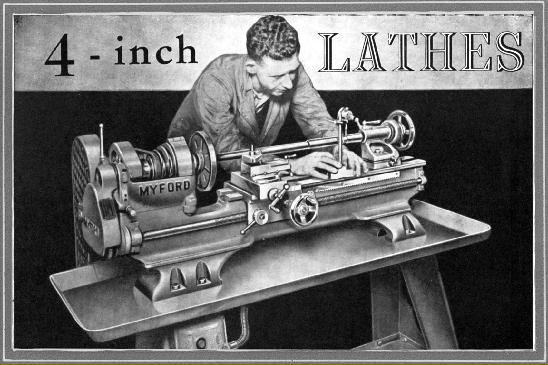
Pre-War Myford MF32 on the maker's sheet-steel stand. The dual marking on the headstock declares "Jones & Shipman Myford". The lathe certainly departs from established Myford in many respects and it may be that J ones & Shipman either designed it or asked for Myford to do so for them, with thoughts of a joint marketing exercise. The headstock lettering has never been seen on an actual lathe, only in sales literature
|
|
|
|
|
|
|
|
|
|
|
 |
|
|
|
|
|
|
Myford MF32/74 tailstock showing some resemblance to that fitted on early models of the ML7
|
|
|
|
|
|
|
|
 |
|
|
|
|
|
|
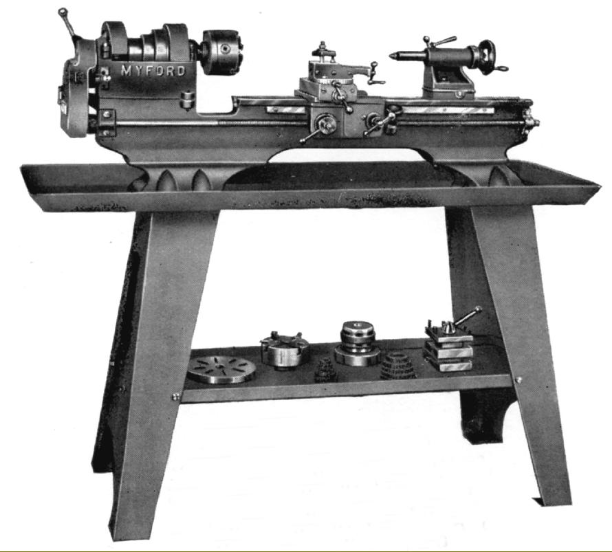
1942 Myford 4-inch precision on the maker's heavier cast-iron stand.
|
|
|
|
|
|
|
|
|
|
|
 |
|
|
|
|
|
|
|
|
On some models the countershaft was neatly built onto the back of the very deep lathe bed with the motor bracket hinged on the back of the headstock-end stand leg.
|
|
|
|
|
|
|
|
|
|
|
|
|
 |
|
|
|
|
|
|
|
|
The only Myford to have transverse T slots in its cross slide.
|
|
|
|
|
|
|
|
|
|
|
|
|
 |
|
|
|
|
|
|
|
|
While the backgear engagement mechanism was rather over engineered - with a collet closer-like lever assembly - there was no catch to hold the changewheel guard closed.
|
|
|
|
|
|
|
|
|
|
|
|
|
 |
|
|
|
|
|
|
|
|
A neat hinged cover guarded the backgear bullwheel.
|
|
|
|
|
|
|
|
|
|
|
|
|
 |
|
|
|
|
|
The headstock carries the Jones & Shipman name - but this was art-worked onto the original photograph, and did not appear on production machines
|
|
|
|
|
|
|
|
|
|
|
|
|
|
 |
|
|
|
|
|
|
1.125" x 12 t.p.i spindle nose - with the "register" behind the thread set at the thread diameter. The domed-headed, knurled-edge bullwheel-to-pulley disengagement pin was spring loaded and fitted with a stiff wire cross piece that dropped into a slot cut in the face of the gear
|
|
|
|
|
|
|
|
|
|
|
 |
|
|
|
|
|
|
Clearly visible just to the left of the front headstock clamping screw is one of the pair of headstock pivot-adjustment screws fitted to some MF32s and MF74s. The other screw was behind the headstock against the other clamping bolt
|
|
|
|
|
|
|
|
|
|
|
 |
|
|
|
|
|
|
Left: the Model designation "MF74" can be seen cast into the backgear guard. For the first time Myford Changewheels were fitted to proper studs with replaceable bearings - thus obviating the age-old problem of the gears wearing on their bores. A strong cast-iron guard covered the changewheels, but there was no way of locking it closed
|
|
|
|
|
|
|
|
 |
|
|
|
|
|
|
The 60 degree V edge to the bed, the clasp-nut adjustment screws set into the single-sided apron, the large boss to support the carriage traverse handwheel, the large diameter to the dial thread indicator - are all visible in this picture
|
|
|
|
|
|
|
|
|
|
|
 |
|
|
|
|
|
 |
|
|
|
|
|
Limited travel cross slide:
The cross slide (there appear to have been two different lengths - short and very short) was unusual in having, like some Emco lathes of recent years, two T slots running from front to rear, rather than in line with the bed. Being short, and lacking an "overhung" type of end bracket as fitted to the 7 Series Myfords, its travel was very limited (and many owners have modified theirs to give more). The picture above shows clearly that when moved back into its operating position, the slide was only supported for half its length - a state of affairs that was far from ideal.
For the first time (left) a Myford was fitted with a replaceable cross slide feed-screw nut, similar to the 7s, but rather larger, and in bronze. The cross feed screw thread was 10 tpi and of square section; it was fitted with a knurled-edge zeroing micrometer dial - something that did not appear again on a Myford-designed lathe until the Super 7 of 1953.
|
|
|
|
|
|
|
|
|
|
|
|
|
|
 |
|
|
|
|
|
|
|
|
The knurled handwheel holding the Dial Thread Indicator in place is as supplied - but the carriage-traverse handwheel, which was originally far too short, is not ...
|
|
|
|
|
|
|
|
|
|
|
|
|
|
|
|
|
|
|
|
|