|
Home Machine Tool Archive Machine-tools Sale & Wanted Repairing a Headstock |
|
|
|
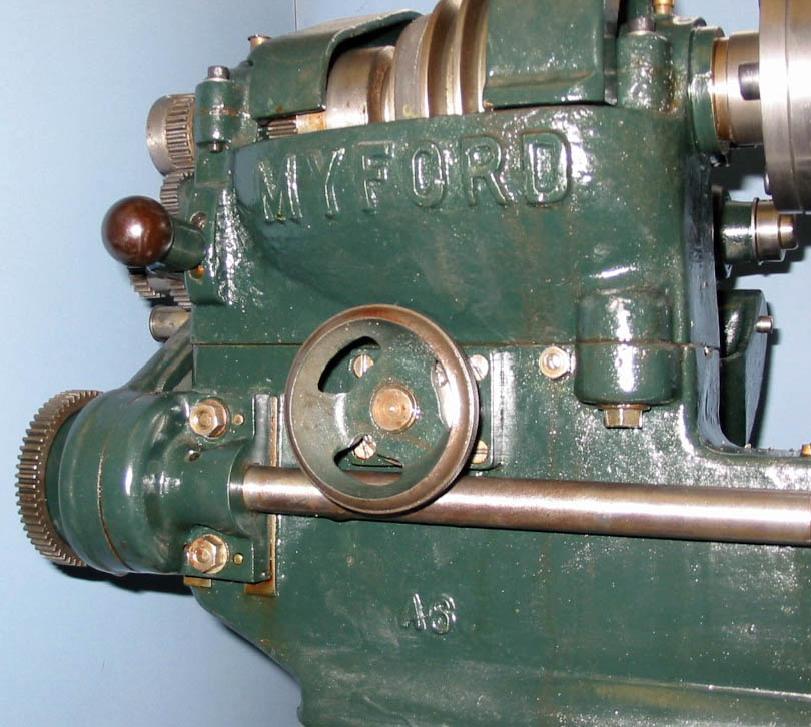
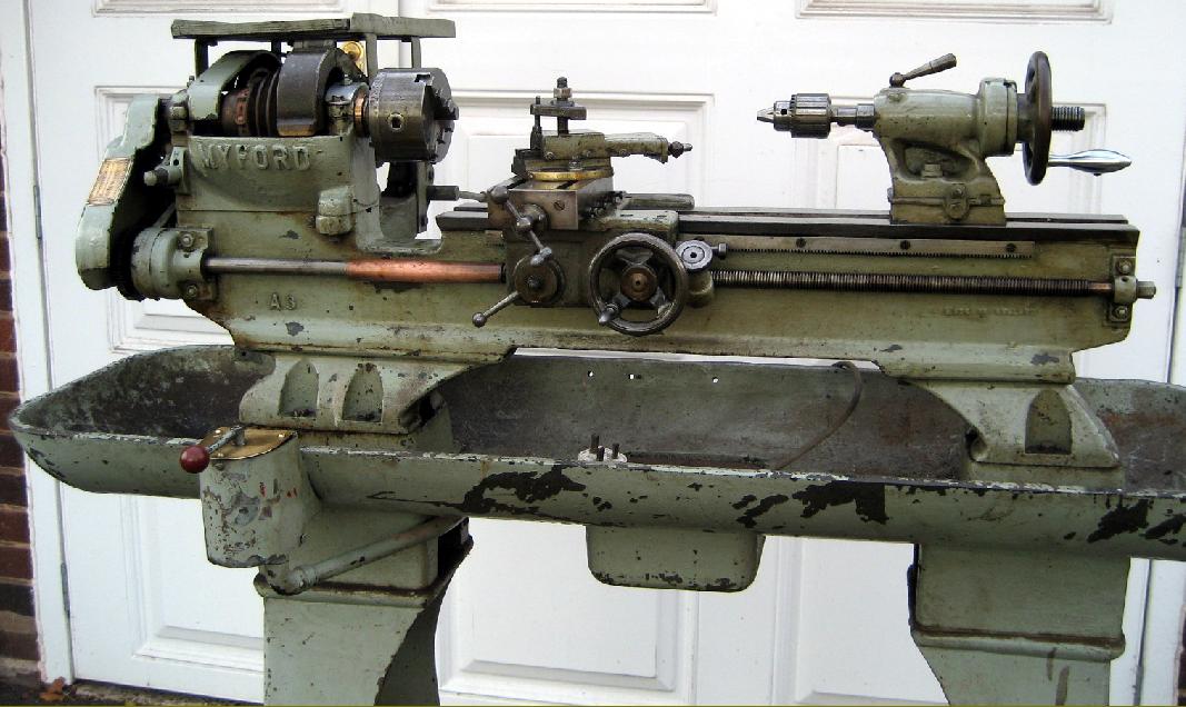
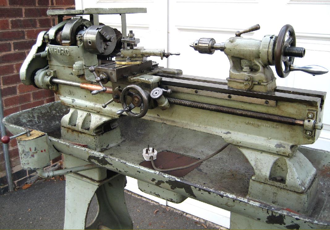
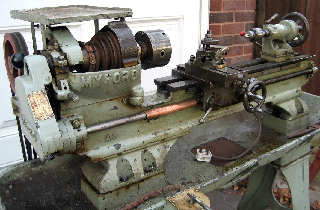
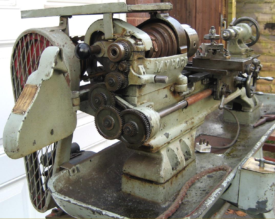
While the first version of the Myford 4-inch precision is very rare, it was also constructed as a capstan version. In both models, instead of the well-separated feet under headstock and tailstock of the later machines, the bed had a form that might be described as "semi-cantilever" with an enormously long foot under the headstock end and a perfunctory support under the tailstock. There were several minor differences as well: the cross-feed screw ran directly in the metal of the saddle (later machines had replaceable nuts); the tailstock used a different casting, the changewheel guard was in aluminium not cast iron and the tailstock-end bearing for the leadscrew was part of the bed casting instead of being bolted on. |
|
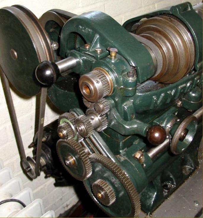
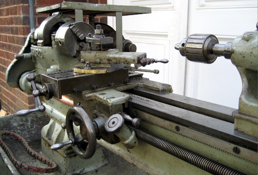
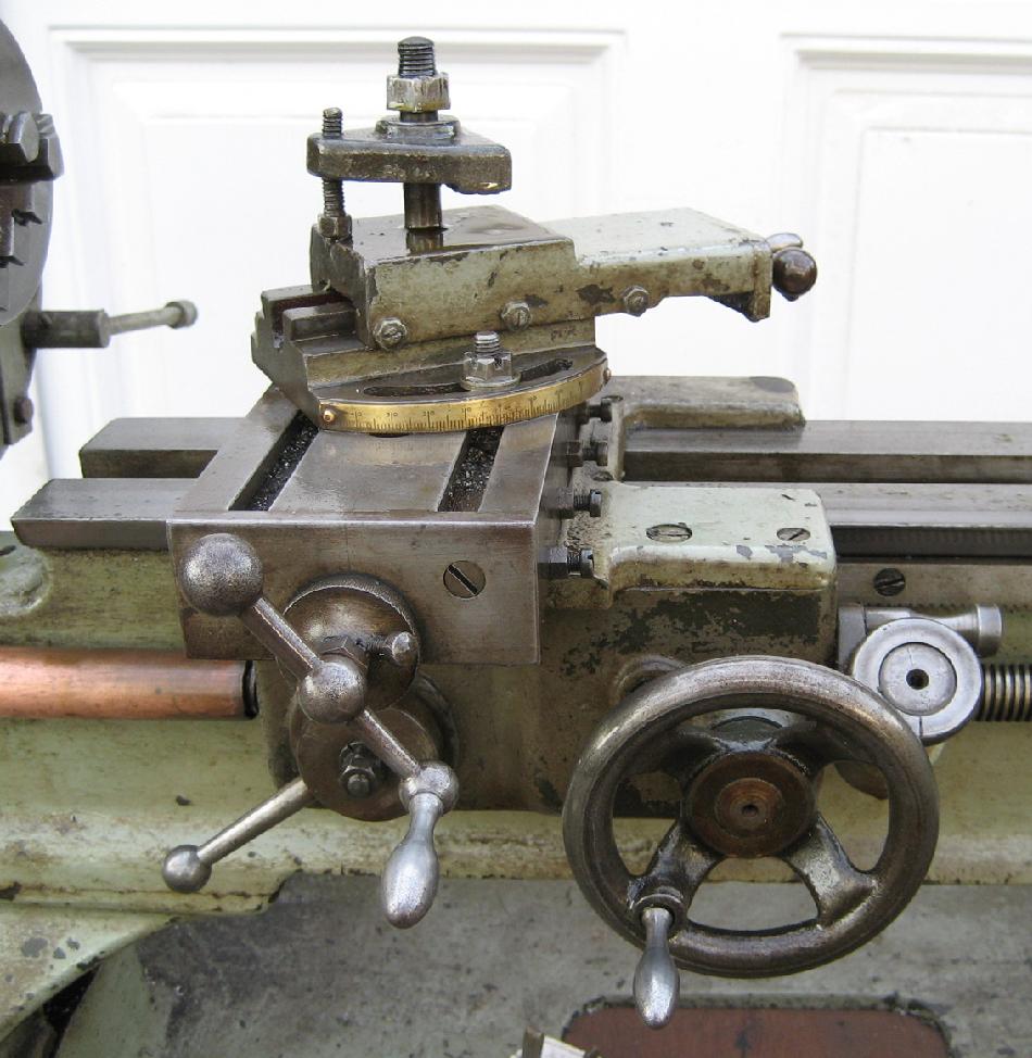
Detail differences and relatively crude engineering: unlike later models with a detachable nut, the cross-feed screw ran directly in the metal of the saddle - as it also did on most ML2 and ML4 models. |
||
|
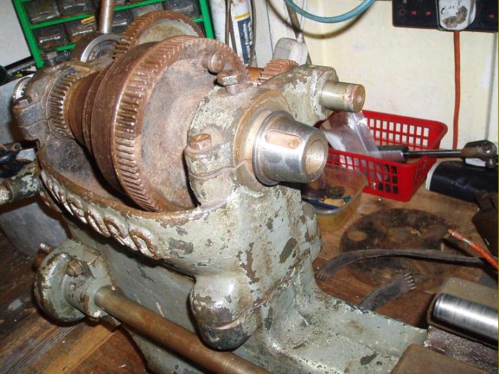
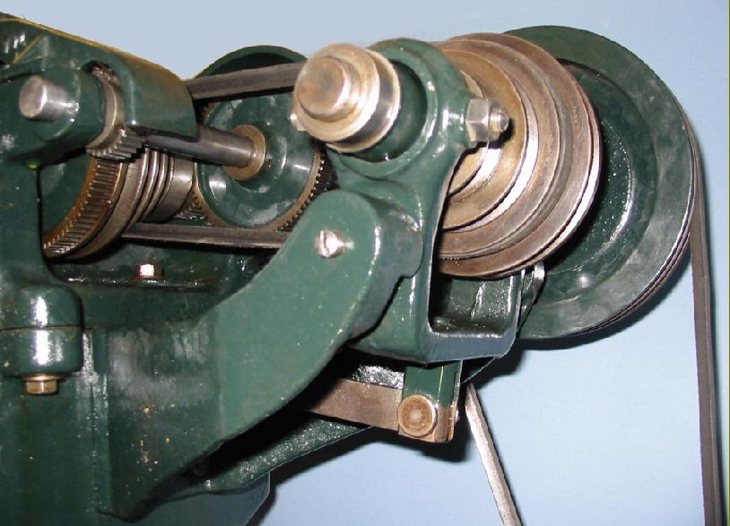
The strips of wood were used to prevent over-tightening of the bearing adjustment screws. The assembly was engineered so that, in theory, all the tolerances used resulted in a bearing that was slightly slack when assembled. The slit in the casting was then used to close down the bearing to set its running clearance correctly. It was even possible - but never admitted by the makers - that for prolonged high-speed use when the bearings might warm up too much, to back off the adjuster nuts one or two flats to give a little more clearance. Interestingly (although a completely different design) in the handbook for the Super 7 there is a reference to setting the bearing clearances to suite different kinds of use |
||
|
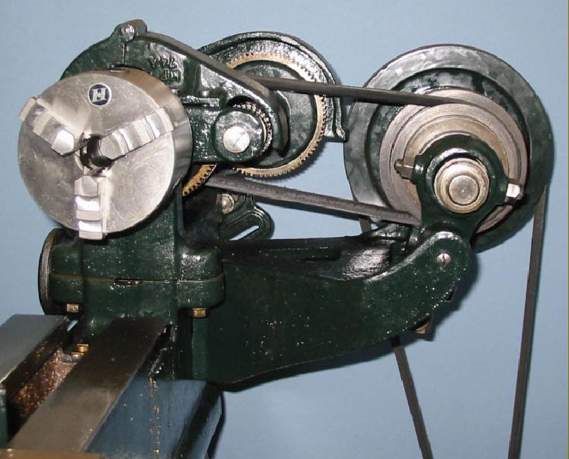
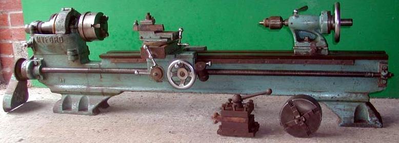
4-inch Myford "Precision" with a Bed-mounted, Integral Countershaft |
|
|
|
|
|
Repairing a Headstock Home Machine Tool Archive Machine-tools Sale & Wanted |