|
Home Machine Tool Archive Machine-tools for Sale & Wanted Monarch 10EE Toolroom Lathe - Page 1 |
|
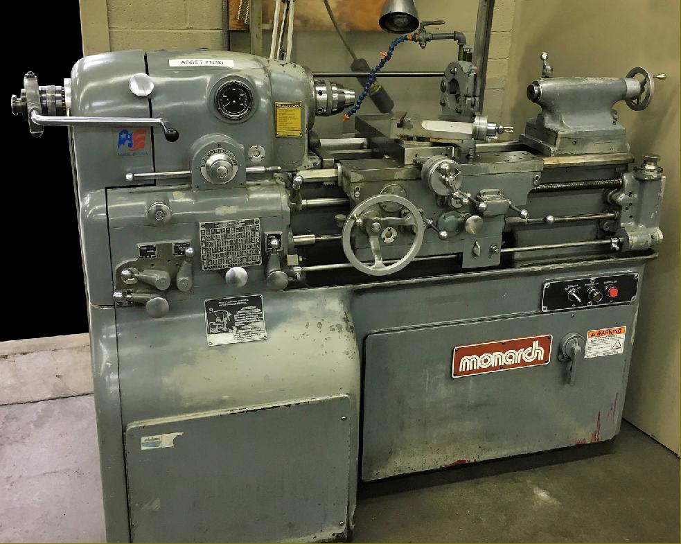
Introduced in 1939 with a 12 inch swing (not the 10 inches that its name would suggest) and a capacity of 20 inches between centres, today the Monarch 10EE Precision Toolroom lathe has a well-established reputation as one of the finest small lathes it is possible to buy. The first two examples produced,, with serial numbers EE-6156 and EE-6207/8, were shipped, respectively, to the Precision Scientific Company Chicago, IL and the Woodward Governor Company of Rockford, IL. The lathe followed and improved upon an already-established design path intended to produce the most accurate of work and the finest of surface finishes: the bed was mounted on a massive and heavy one-piece cast-iron stand with the entire drive system isolated inside and the headstock spindle turned by belt. The arrangement provided great stability and removed any chance of vibration from motors or gearboxes being transmitted to the workpiece. In addition, whenever sliding and surfacing feeds were selected (as distinct from gear-driven screwcutting) the precaution was taken of using a flat-belt to drive the gearbox - so isolating the drive from uneven gear impulses that might spoil the surface finish. Early machines, made until a change-over that lasted through 1944 and into 1945, are now referred to as the "old height" models and may be distinguished from later versions by the (beautifully-made) circular feeds-and-threading selector arrangement on the face of the gearbox. There were two types of "round" box: one used a rectangular knob that was pushed in and turned to select a gear range and another version where the ball lever was first rotated to disengage the gearbox, the centre wheel turned to select the range and then the ball lever turned again to re-engage the drive. One sub-version, the very rare ELSR, had a form of electronic leadscrew reverse incorporated, a fitting intended to speed up and make safe repetitive screwcutting operations. The screwcutting gearbox box was able to generate 30 different feeds from 0.001" to 0.0075" per revolution of the spindle and 50 combinations of threads from 3 to 92 t.p.i; a further distinguishing feature of these very early models was the open changewheel drive to the screwcutting gearbox - later lathes have the gears fully enclosed in an oil bath case. Although found very infrequently, it was possible to order a dual inch/metric screwcutting gearbox - an example is shown lower down this page. |
|
Continued: |
|
Lathes fitted with ELSR (Electronic Leadscrew Reverse) can be easily identified by a rectangular-form threading selector box with a chrome-plated, left-to-right travel lever fitted on top and a long rod running from headstock to tailstock with support at its far end in a curved bracket. |
|
Continued: |
|
End covers removed showing the base-mounted DC motor and reduction gearbox and, at the top, the flat-belt drive system for the non-screwcutting feed to the gearbox. |
||
|
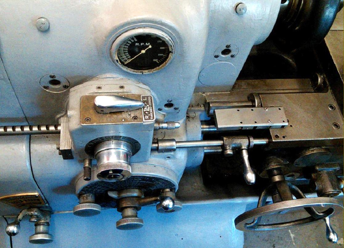
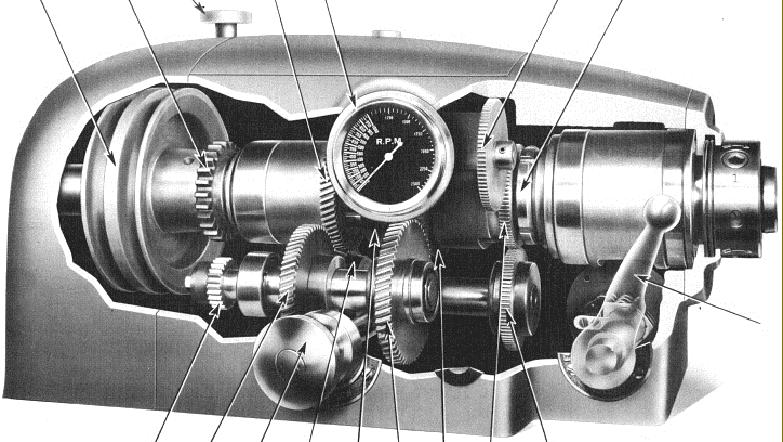
Complex and effective "Dial-in" screwcutting and feeds gearbox of the first Monarch EE Toolroom lathe. |
||
|
A basic test for a genuine toolroom lathe is that the width of the bed should be at least equal to, or greater than, the distance from it to the centre of the spindle. In addition, the EE has saddle arms which, at 20.5", are almost half the length of the bed ways; they are aligned by four ball bearing "gibs", mounted on eccentric studs, at the end of each arm - picture below. |
||
|
|
||
|
The micrometer dials were appropriately large and very clearly engraved with divisions that indicated the number of thousandths of an inch being taken off diameter. The dials' chrome finish was softened by vapour blasting to give an anti-glare effect. |
||
|
|
||
|
|
||
|
On all but the earliest machines the drive from headstock to screwcutting gearbox was totally enclosed and automatically lubricated. To cut metric threads the cover had to be unbolted and translation gears substituted for those already in place. An English-metric gearbox was offered as an optional extra. |
||
|
The set-over tailstock had a hardened, graduated spindle of 1.75" diameter with a travel of 3.5" The handwheel was fitted with a micrometer collar. |
||
|
Home Machine Tool Archive Machine-tools for Sale & Wanted |