email: tony@lathes.co.uk
Home   Machine Tool Archive   Machine-tools for Sale & Wanted
Machine Tool Manuals   Catalogues   Belts   Books   Accessories

Monarch 10EE Lathe Early Version

10EE Lathe Home Page

Monarch Home Page  10EE Screw Machine   10EE Photographic Essay

Monarch "Factory Tour"   History of Monarch (download)

A Manual is available for the early Monarch 10EE

The special high-quality flat-belt can be ordered here

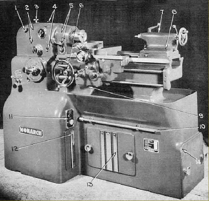
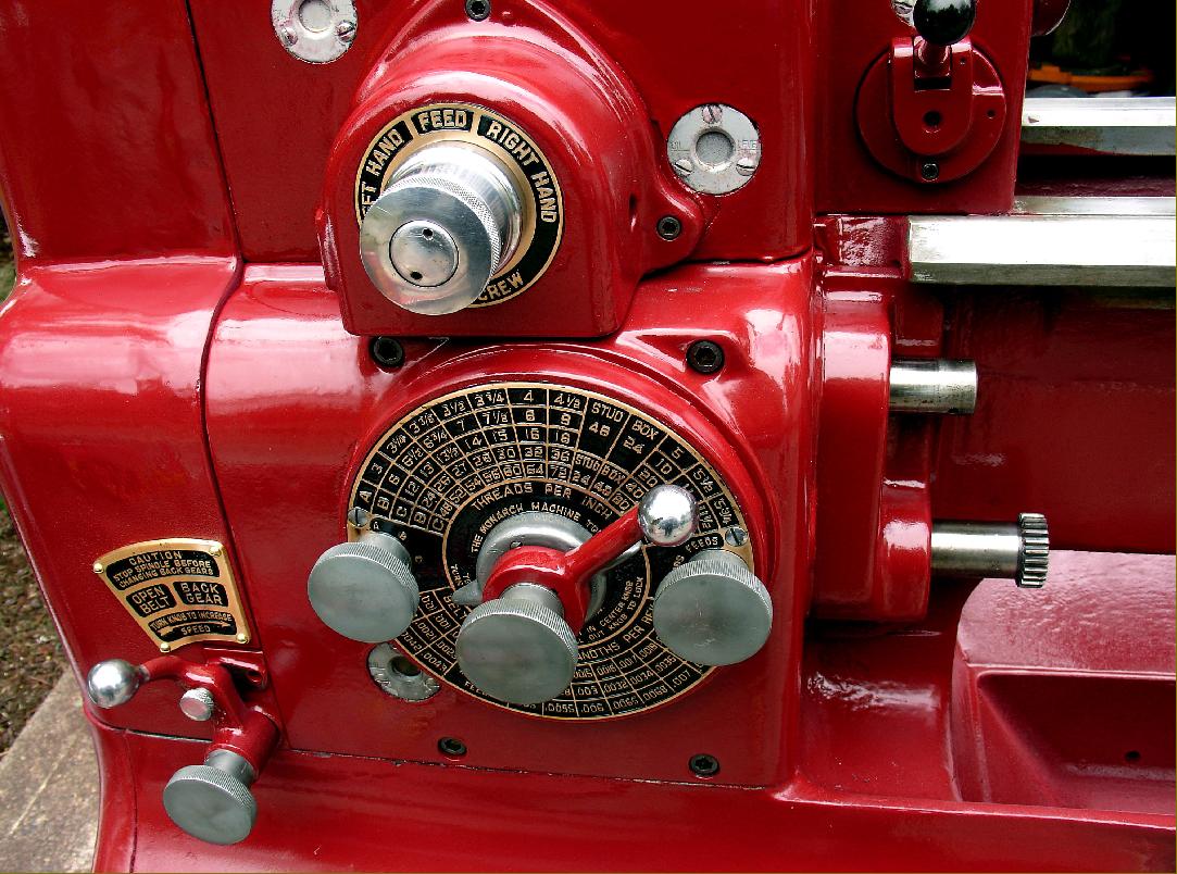
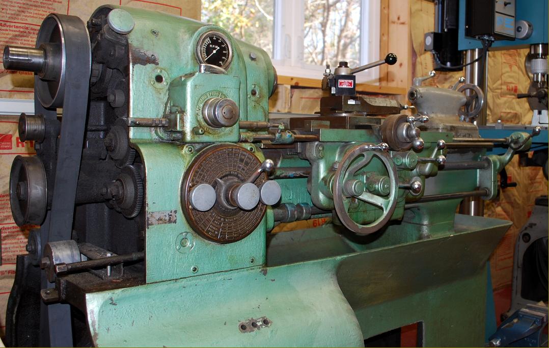
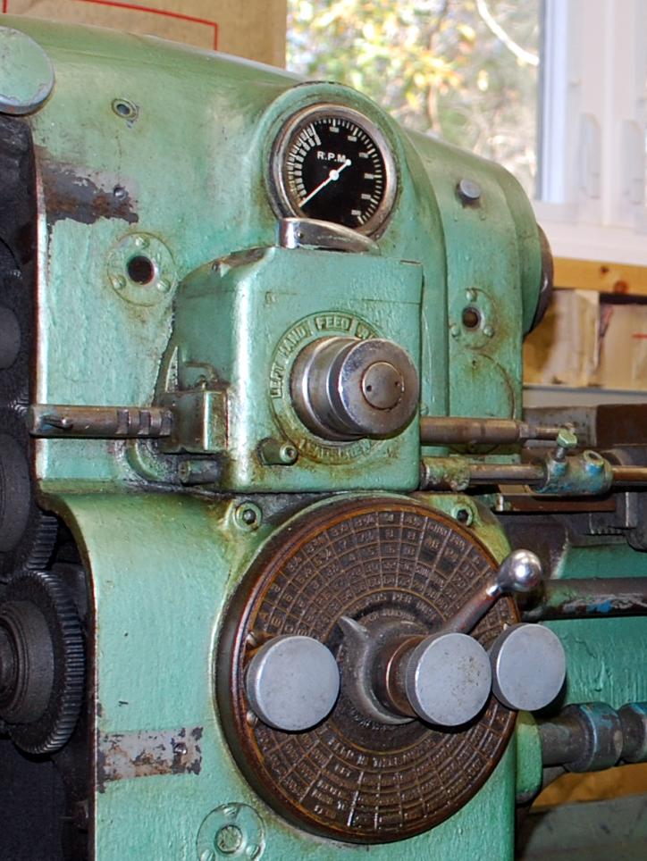
The first monarch 10EE lathes (this illustration is from an operator's  Manual dated April 11, 1941) can be easily distinguished by the round gearbox selector plate with its push/pull/twist handle arrangement.

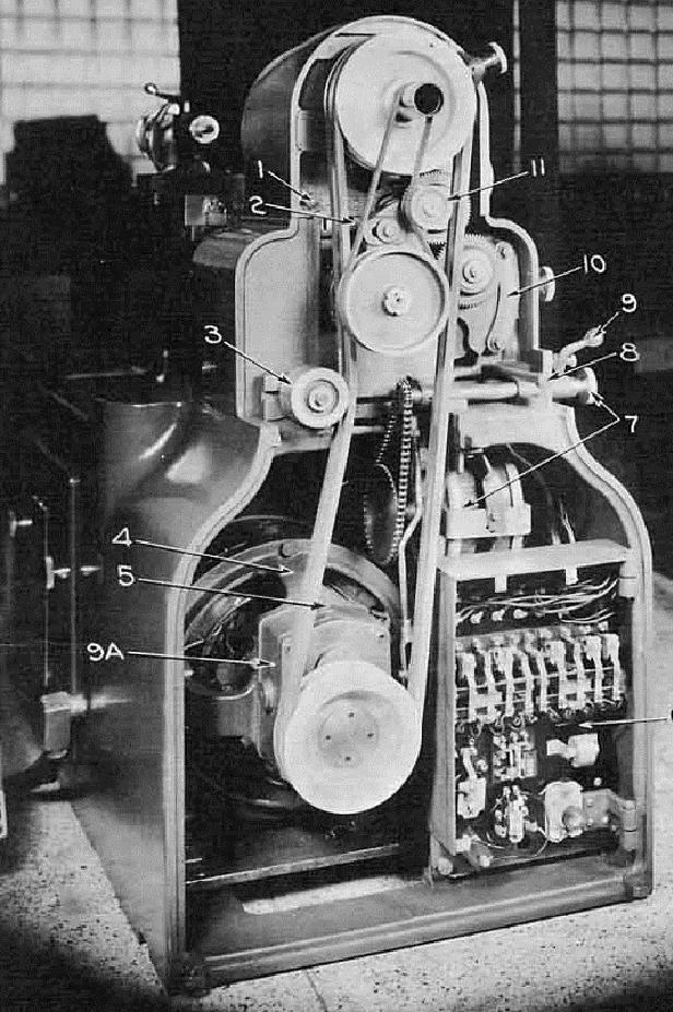
The gear drive to the screwcutting gearbox was left open on the first lathes of the series. The general arrangement of the various drives remained the same throughout the life of the machine.

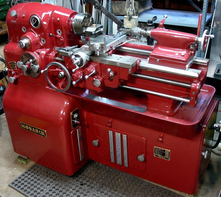
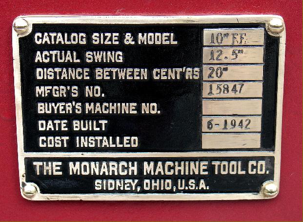
Massive, imposing and handsome - an early 10EE refurbished by its enthusiastic owner. The version the keeper reports was built during WW2, the dials and name plates being made from brass instead of the usual aluminium the latter being, according to some sources, a strategic material and not to be used unless essential. Other examples of the 10EE have their  dials and plates pressure die cast in ZAMAK - an initially expensive process when counting the cost of the dies but thereafter only a few dollars each.

Build plate - 1942

Taper-turning attachment

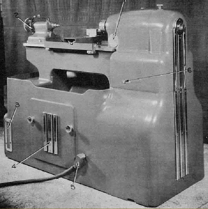
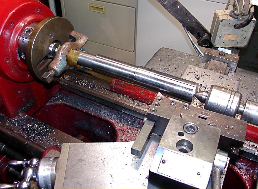
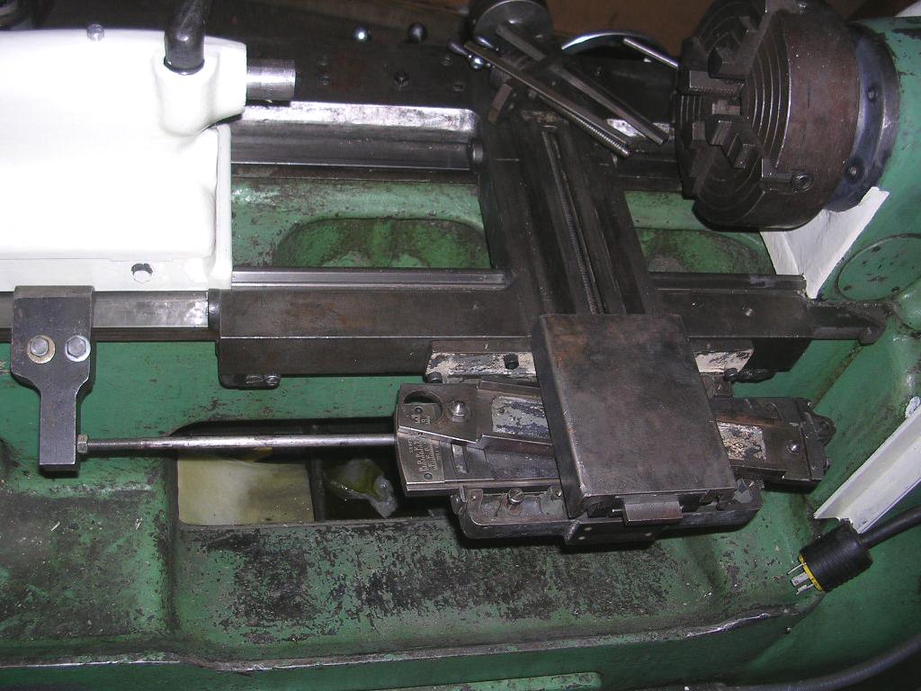
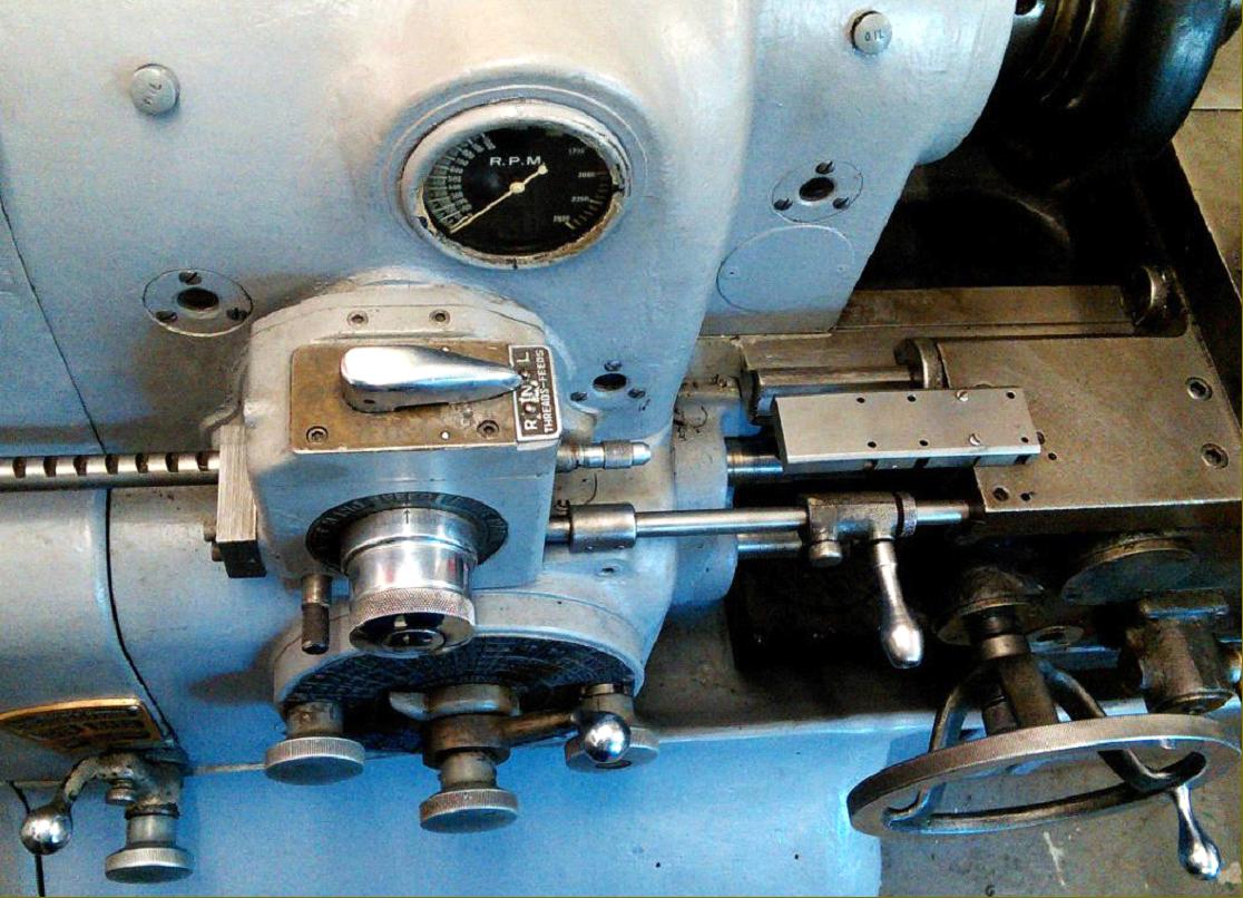
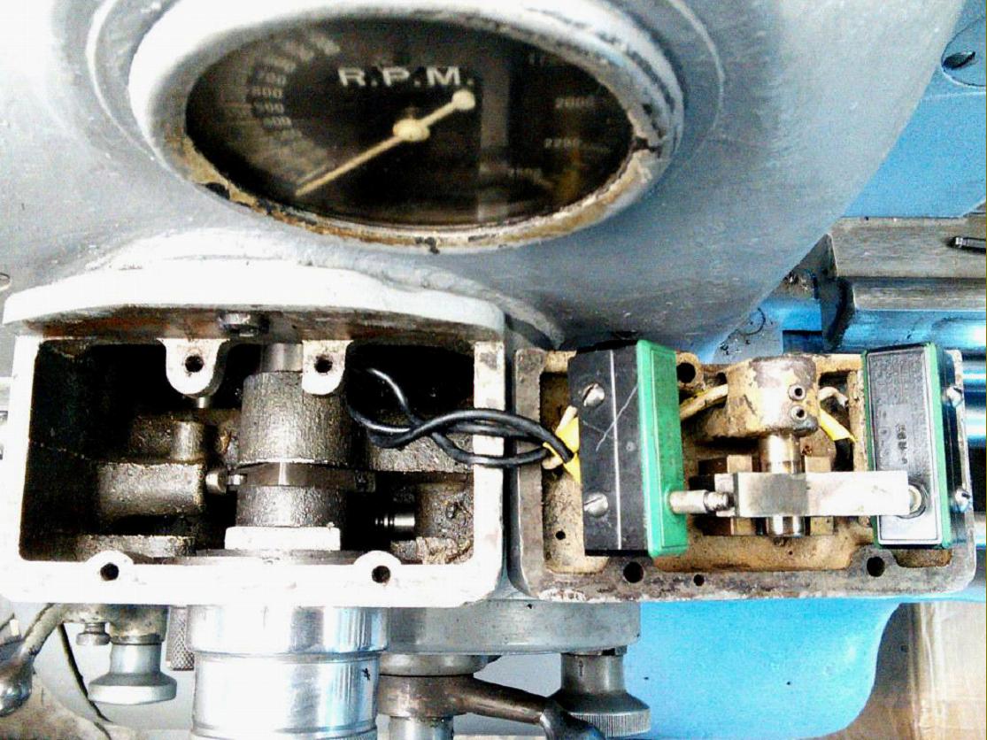
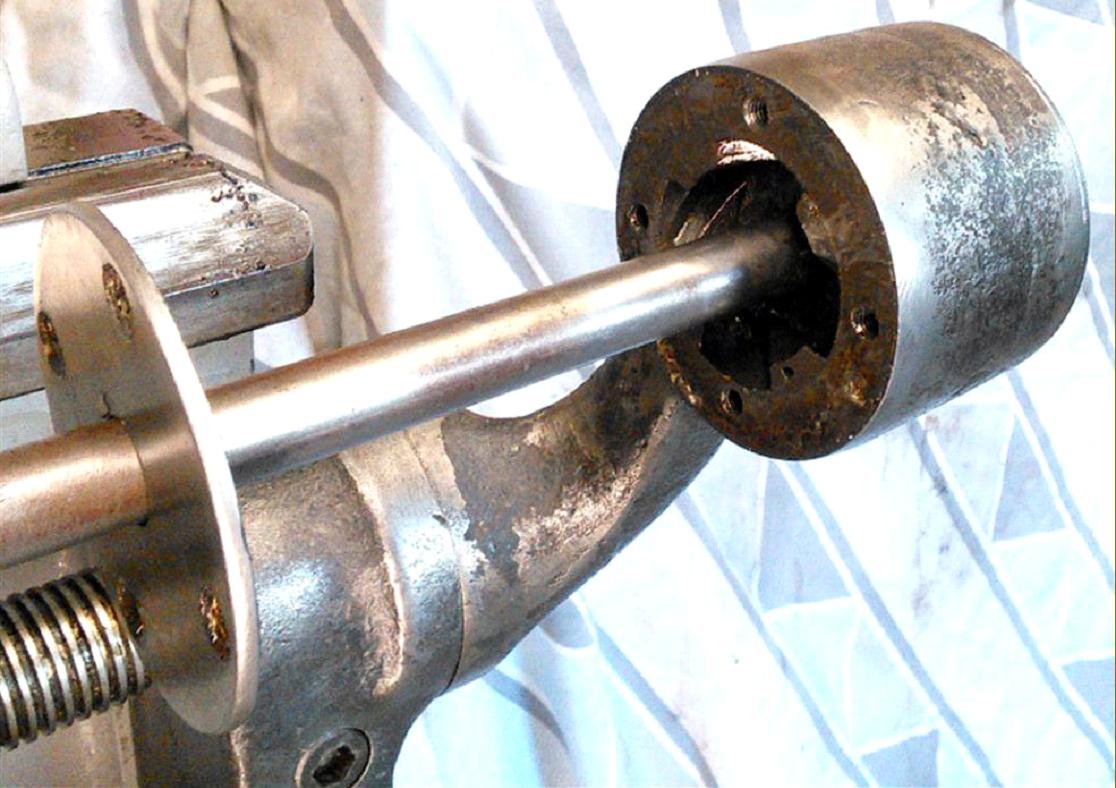
Above: thought to be a very early example, this 10EE has a distinctly-different rectangular-form threading selector box on the front face of the headstock and a long rod running parallel to the top edge of the bed. The selector box, instead of just a dial selector on its front as on normal machines, had a chrome-plated, left-to-right travel lever fitted on top - these modifications indicating that the machine is a round-dial version of the ELSR Type (Electronic Leadscrew Reverse).  However, the ELSR was misleadingly named, for it did not actually reverse the leadscrew, its function was to provide a repeatable method of stopping the spindle at some chosen point for operations such as threading to a shoulder, or into the bottom of a blind hole, without the risk of over-running.
Instead of a headstock-mounted drum switch, a control rod was arranged to run from the threading selector housing through the top of the apron and from there to a support bracket fixed to the tailstock end of the bed. Keyed to the rod was a sliding motor-control lever, locked in place by a thumb-screw this acted as an adjustable stop. At the tailstock end the rod had a helical gear that turned on a white-metal bearing inside the support housing: moving the lever up and down caused the rod to slide left and right. At the headstock end the control rod had several grooves machined so as to form a circular rack, these engaging with a drum sporting two square cams off-set at 45° degrees to each other that operated, via a sliding rocker, forward and reverse micro-switches. There was also a small plunger fitted to the lower left of the threading control switch housing used as a safety device to lock the control rod in neutral and so avoid unexpected starts when working on the set-up. On top of the housing was a 3-position mechanical switch that slid the rocker (between the two square cams) to select left or right turning, or neutral, in which latter case neither cam was engaged and the spindle would not start. For normal turning and right-hand threading, the switch would be set to RIGHT. Pressing the control lever down caused the spindle to turn forwards and the carriage to move towards the headstock until it pushed on the lever and opened the contactor of the DC motor. The effect of opening the contactor was to bring into operation an electrical brake and this provided -  if the same spindle speed was kept for all cuts-  a repeatable stop. At low speed the system became even more effective and would give repeatability to within a fraction of a turn.
For left-hand threading or feeds the leadscrew was reversed, in the usual way on the threading box and the switch set to LEFT - so reversing the operation of the control lever. Pressing the control lever down set the motor into reverse with the carriage still travelling towards the headstock, so that the control rod could stop the motor using the same method as for right-hand threads. Once the spindle had stopped, the tool was retracted and the spindle reversed - this bringing the carriage back to the start of the thread without the need to open the (oil-fed) leadscrew clasp nuts. Combined with the very useful 2-turn positive threading stop on the cross-slide screw, this arrangement made for a most efficient and accurate thread-cutting system.

Lathes fitted with ELSR  (Electronic Leadscrew Reverse) can be easily identified by a rectangular-form threading selector box with a chrome-plated, left-to-right travel lever fitted on top and a long rod running from headstock to tailstock with support at its far end in a curved bracket.

Lid of the threading selector box  removed. To the right can be seen the two square cams off-set at 45° degrees to each other, and the micro-switches that they operated

10EE Lathe Home Page   Monarch Home Page  10EE Screw Machine   10EE Photographic Essay   

A Manual is available for the early Monarch 10EE

Monarch "Factory Tour"   History of Monarch (download)


The special high-quality flat-belt can be ordered here

Monarch 10EE Lathe Early Version
email: tony@lathes.co.uk
Home   Machine Tool Archive   Machine-tools for Sale & Wanted
Machine Tool Manuals   Catalogues   Belts   Books   Accessories