 |
|
|
|
|
|
|
|
|
|
|
|
|
|
|
|
|
|
|
|
|
|
|
|
|
|
|
|
|
|
|
|
|
|
|
|
|
|
|
|
|
|
|
|
|
|
|
|
|
|
|
|
|
|
|
|
|
|
|
|
|
|
|
|
|
|
|
|
|
|
|
|
|
|
|
|
|
|
|
|
|
|
|
|
|
|
|
|
|
|
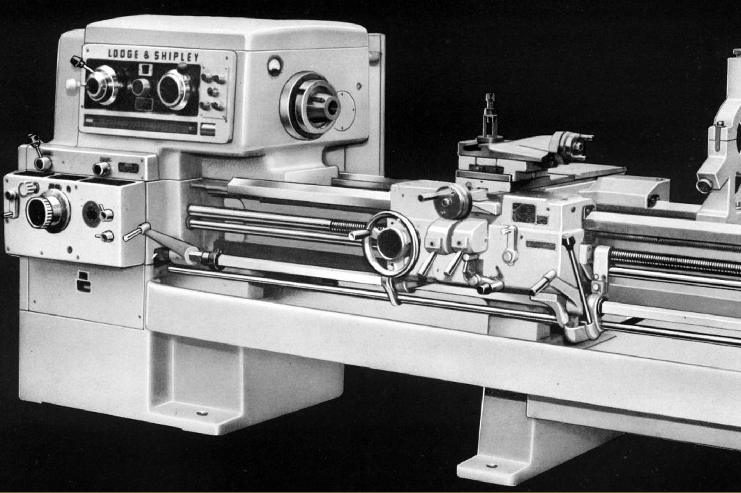
"Powerturn" lathes were manufactured during the 1950s and 1960s by Lodge & Shipley, a company famous since 1891 for their no-nonsense, heavy-duty "engine" lathes - the American term for a general-purpose, backgeared and screwcutting type. So successful was the Powerturn that another American company, Kearney & Trecker, who had an established a presence in the UK building their well-known milling machines and the superb CVA precision lathe, acquired the rights for its manufacture in England. Even judged against the standards of the 21st century the Powerturn - a lathe closely based on the maker's earlier "X Series" and using many of the same design features - was a thoroughly modern, well thought out design with numerous features to make the life of the operator both productive and easy. Besides the usual refinements expected on a lathe of this type, spindle speeds were selected by twin rotary controls with colour coding and indicator lights for fool-proof operation, a multi-plate, combined spindle clutch and brake was fitted as standard, the leadscrew could be reversed from the apron without stopping the headstock spindle - a real boon when screwcutting - the tailstock spindle was able to be advanced and retracted at high or low speed (with 1:1 and 5:1 gearing) and the hardened and ground outer pair of bed V-ways - and the cross-slide ways - could replaced when worn, so extending a machine's productive life by many years.
Only the three larger models were made in England, with swings of 18", 20" and 24" (457 mm, 520mm and 625 mm) respectively labeled as the Types 1610, 2013 and 2013-17. There were also two smaller models, the 13" and 16", but these were confined to the American market. All three UK versions could be had with 54, 78 or 126 inches (1370, 1980 or 3200 mm) between centres and, whilst both all-inch and all-metric models could be supplied, the makers offered the option, if required, of machines with inch leadscrews fitted with metric translation changewheels for screwcutting and metric feed screws and dials on the compound slide rest.
Continued below:
|
|
|
|
|
|
|
 |
|
|
|
|
|
Continued:
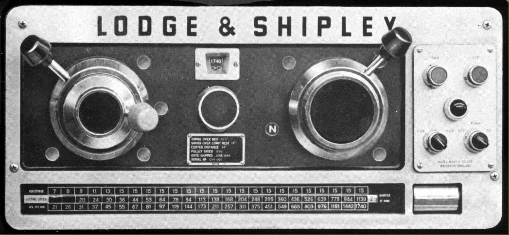
Like all Lodge and Shipley lathes the bed of the Powerturn lathe was massively constructed. Cast in nickel iron, and with the company's trademark elliptical webs between the walls, it was fitted with replaceable outer bed-ways in a graphite alloy steel hardened to 62-64 Rockwell "C" and then precision ground. The ways were tenoned into the bed, secured by bolts and could, claimed the makers, be replaced without having to return the lathe to the works. Designed for a long and reliable life the headstock could be driven by either a 15 or 20 h.p. motor and had 24 spindle speeds. Three speed ranges were available labeled "A", "B" and "C" with "A" using the 15 h.p. motor and running from 14 to 1160 r.p.m. - whilst "B" and "C" used the 20 h.p motor and had ranges of 21 to 1740 r.p.m. and 24 to 2000 r.p.m. respectively. The spindle-speed control dials were designed to let the operator not only select the right speed for the job, but also to know the amount of power it was safe to transmit. Having determined the correct linear cutting speed, a drum-type indicator was used to convert this to a spindle speed, which was then entered on a dial by rotating a knob in the middle of the headstock face. As this was done coloured lights automatically illuminated to show the operator the correct settings of the control levers. As a further refinement the turner could, having established one speed, pre-set the next ready for instant selection. An ammeter was provided to let the operator check that, for a given job, the machine was being run to its maximum capacity, yet not being overloaded - a chart on the headstock providing the figures required. For example, on the "C" speed range at 24 r.p.m. the maximum permitted power setting was 8 h.p., at 52 r.p.m 15 h.p. could be employed and at all speeds including and beyond 77 r.p.m. full power was allowed. With such a wide range of speeds available, from usefully low to very high, it was possible for one machine to undertake a wide variety of tasks from the machining of small components to the turning of large castings on a faceplate - and careful low-speed thread cutting.
Manufactured from nickel-chrome steel the 2-inch (51 mm) bore headstock spindle had a hardened nose of the American long-nose taper type in an L1 size - though a cam-lock was available as an option. The model 1610 used a No. 4 Morse taper in the nose, the larger 2013 and 2013-17 versions had a No. 5. The spindle ran in three bearings: those at the nose and in the centre being opposed taper rollers whilst that at the rear was a double-row taper roller with a floating outer race to allow for spindle expansion. The spindle clutch could be operated by either of two control levers - one on the carriage and the other next to the screwcutting gearbox - with the spindle brake was applied automatically as the clutch was withdrawn. Headstock gears were naturally of high quality: precision-shaved and hardened spur gears running on hardened and ground shafts all turning in anti-friction bearings. Lubrication was automatic and under pressure - a centrifugal pump lifting oil from a separate reservoir though a replaceable 'Purolator' cartridge filter to the headstock where it was directed by an "oil spinner" and distribution tray connected to a number of feed pipes. By directing oil back to a separate container (and so removing much of the heating effect from gears churning it round) a more uniform temperature was maintained throughout the headstock.
Continued below:
|
|
|
|
|
|
|
 |
|
|
|
|
|
|
Continued:
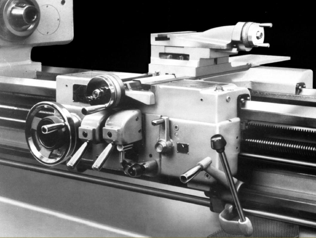
Very heavily built, the carriage slid on hardened and ground steel V-ways at back and front - and also used the flat "tailstock way" for additional support. The saddle was equipped with long wings to the left and right, with the cross-slide sitting, perfectly supported, almost in the centre - the bed ways being arranged so that the carriage could slide partially past the headstock to bring the toolpost right up to the spindle nose. To ensure as accurate a fit as possible to the bed, pairs of adjustable gib strips were used at both the front and rear of the saddle.
Tapered gib strips were fitted to top and cross slide and the unusual design of their ways mirrored that used on the older range of "X" lathes - inverted dovetails and a "drop-centre" section aiming to improve rigidity yet maximize the lathe's swing. The ways for the cross-slide could be unbolted and replaced and careful attention was paid to the hard-working cross slide screw and its nut: the screw was flame hardened, ball races were fitted to absorb thrust (and improve feel) and a double compensating nut used to adjust out backlash. To limit cross slide travel when threading or boring an ingenious built-in "micrometer ball stop" was provided - this being the same long-established and successful system offered on Loge and Shipley lathes since the 1920s. The micrometer dials were beautifully engraved, each division representing 0.001" off diameter (0.02 mm on metric machines) and, to ensure that the setting was not disturbed, dial locking was by through-the-face-fastenings operated by neatly designed levers.
Equipped with hardened and shaved alloy steel gears, and hardened shafts running in anti-friction bearings, the apron drove the power sliding and surfacing feeds through adjustable safety-overload clutches. A most useful standard fitting, operated by a lever at the extreme right of the apron's front face, was "reverse to the leadscrew", a system that allowed the spindle to continue running, the clasp nuts to stay engaged and so completely removing the need to refer to the thread-dial indicator when screwcutting. Although limited to spindle speeds under 400 r.p.m. leadscrew reverse was not only useful when cutting standard threads, but a tremendous help when it was necessary to generate metric or odd threads and leads - or on similar occasions when the thread dial could not pick up the engagement point. Two automatic disengage stops were also provided for both screwcutting and power sliding in each direction - an especially useful (and safety-enhancing) feature when turning or threading up to a shoulder or into a blind hole. In addition to the normal feeds through the screwcutting and feeds gearboxes the makers also list two designs of power rapid feed to the carriage. Both used separate motors driving, through worm-and-wheel gearing and multi-disc overload clutches, reduction gearboxes bolted to the tailstock end of the bed. One unit worked through an extension to the normal powershaft with the other employing a separate left and right-hand threaded shaft running down the back of the bed and passing through left and right-hand bronze nuts carried in a housing attached to the back of the carriage. On the latter unit (identical to that employed on the older X series of lathes) an independent control unit, operated by a lever on the front face of the apron, enabled either nut to be restrained and rapid traverse of sliding and surfacing feeds selected in either direction. Pressing the handle operated the feed whilst releasing it caused an instant return to neutral and immediate disconnection of the drive. Any movement of the carriage - by hand or under power - drove a plunger pump in the apron that provided a supply of filtered oil to the apron internals and also all the saddle, cross and top-slide ways. The pump could also be operated manually, useful when the carriage was stationary and the cross or top slide in continuous use - or if the lathe had stood unused for some time.
Continued below:
|
|
|
|
|
|
|
|
|
|
|
|
|
 |
|
|
|
|
|
|
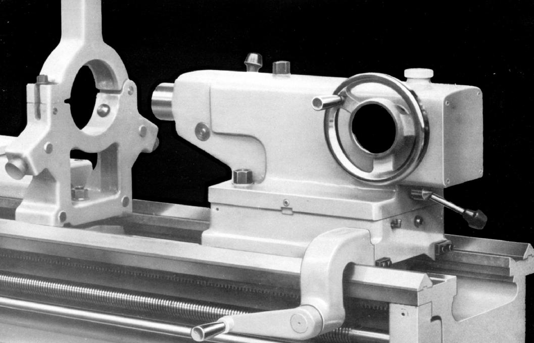
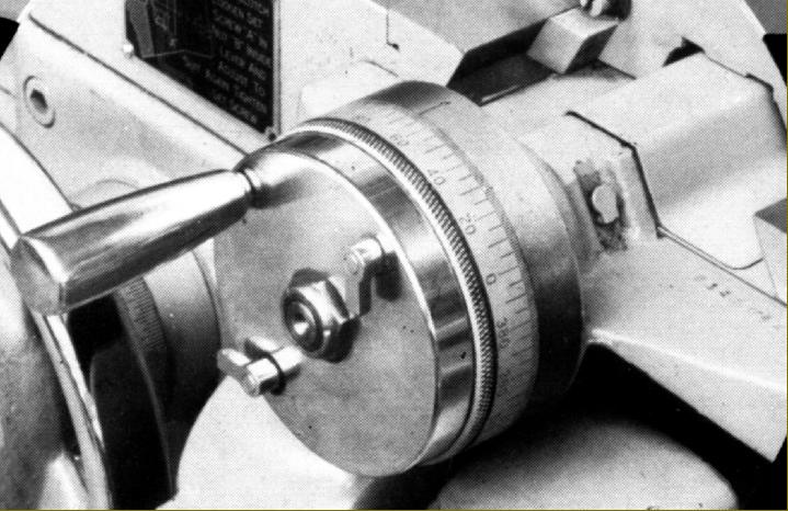
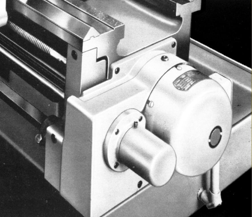
2-speed tailstock with 1:1 and 5: 1 drive, built-in lubrication and a 90-degree handwheel.
|
|
|
|
|
|
|
|
|
Continued:
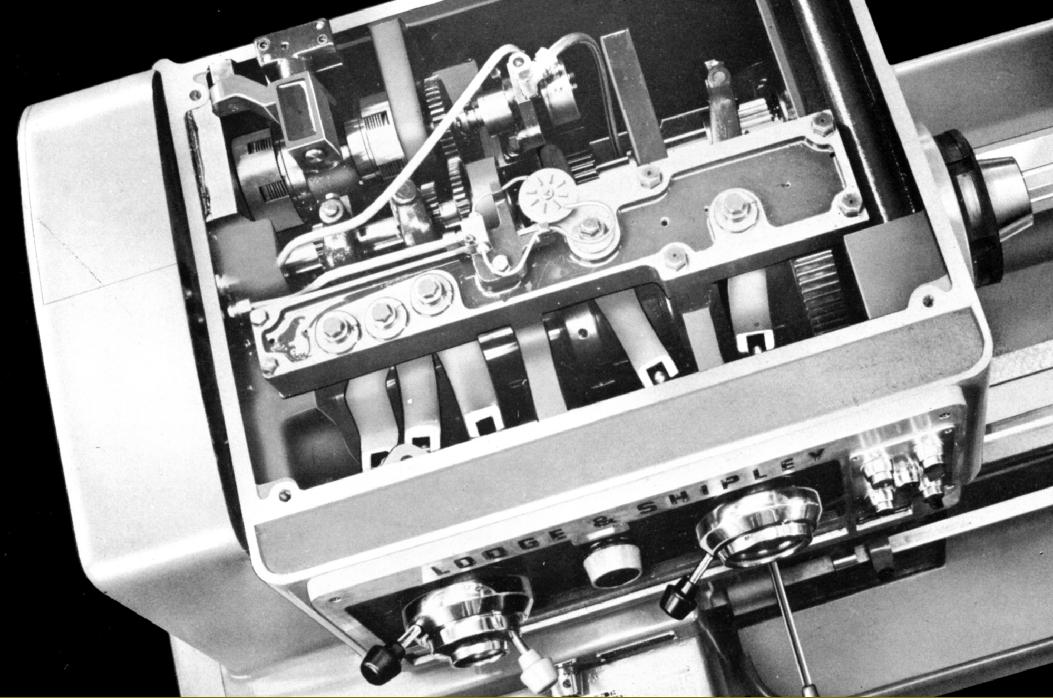
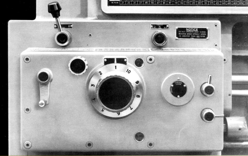
Described as offering "Fingertip Control of Threads and Feeds" the screwcutting gearbox was completely enclosed, pressure lubricated and with simple, easy-to-use rotary and lever controls. It was a traditional Lodge and Shipley design - having been first seen on "X" models - and contained the usual high-quality components: hardened and shaved gears and hardened shafts running in anti-friction bearings. 73 pitches and rates of feed were available, but of these (a very generous) 55 could be directly selected by the controls, the other 18 required the substitution of changewheels on the end bracket. When fitted with the necessary translation wheels an English screwcutting gearbox could generate a full range of 55 metric pitches, and a metric lathe 55 English threads. On both English and metric machines module and diametral pitches could also be generated by the substitution of appropriate changewheels. Sliding and surfacing feed rates varied from 0.0007" to 0.187" (0.0019 to 0.476 mm) per revolution of the spindle whilst English pitches (with an inch leadscrew) ran from 1 to 256 t.p.i. and metric (with a metric leadscrew) from 0.125 to 32 mm pitch. The design of the gearbox and its operation were interesting - and removed the need for the operator to struggle with a reluctant-to-shift tumbler lever. This was achieved by separating the sliding tumbler gear selector from the fixed cone of gears by the use of clever "alligator" jaws. When the jaws were opened - by a lever on the left of the box - the tumbler could be moved sideways by rotating a dial, marked with the various thread positions and working through a pinion, segment lever and fork assembly. When the desired pitch was indicated on the dial the jaws lever was closed, so engaging the gears and ensuring that they meshed correctly. Two other levers, to the right of the rotary dial, were juxtaposed to complete the sequence necessary to select the full range of pitches and feeds. Oil was lifted from the base of the gearbox by a plunger pump and sent to a distribution plate from where it was directed to the gears, shafts and their bearings - and also to the leadscrew and powershaft support bearings.
With built-in gearing the tailstock spindle could be advanced at a 1:1 ratio for normal work or through a 5: 1 reduction ration for heavy drilling. The spindle was hardened and ground and fitted with a tang knock-out slot. Driven along the bed by a hand-operated crank working against the carriage rack the unit could be locked by either the usual over-centre lever - or tightened down further through by the use of two additional clamping bolts. An lubrication reservoir was incorporated in the base and lubrication fed to the bed ways by gravity.
Supplied as standard with each machine was a faceplate; headstock Morse taper adaptor sleeve; Morse centres for headstock and tailstock; a fixed steady with plain bronze jaws (capacity 0.5" to 5" for the Type 1610 and 0.5" to 6" for the two larger machines); micrometer dial for the carriage handwheel; a deep chip tray; single-tool toolpost; a thread-dial indicator (English leadscrew version only); 38t gear to generate 19 t.p.i. threads and a set of spanners (wrenches). At extra cost the makers could supply a motor and electrical control gear; a 4-way rapid traverse to the carriage; taper-turning attachment; traveling steady; oversize fixed steadies (4" to 8" for the Type 1610 and 5.5" to 10" for the Types 2013 and 2013-17); direct-reading micrometer dial for the cross slide; coolant equipment; micrometer carriage stop; 4-way toolpost; quick-change toolpost; heavy-duty tool-block for cross-slide mounting (to replace the top slide); English-metric and metric-English translation changewheels; translating gears for diametral and module pitches; Tru-grip collet chuck (up to 2-inch capacity); hydraulic copying (tracer) equipment and the usual range of 3 and 4-jaw chucks..
|
|
|
|
|
|
|
 |
|
|
|
|
|
|
|
|
|
|
 |
|
|
|
|
|
|
Having determined the correct linear cutting speed, a drum-type indicator was used to convert this to a spindle speed - which was then entered on a dial by rotating a knob in the middle of the headstock face. As this was done coloured lights automatically illuminated to show the operator the correct setting for the spindle-speed levers.
|
|
|
|
|
|
|
 |
|
|
|
|
Described as offering "Fingertip Control of Threads and Feeds" the screwcutting and feeds gearbox was completely enclosed, pressure lubricated and with simple, easy-to-use rotary and lever controls.
|
|
|
|
|
|
|
 |
|
|
|
|
|
|
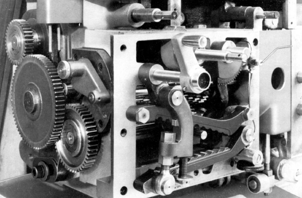
Inside the screwcutting & feeds gearbox Note the separation of the sliding tumbler gear selector from the fixed cone of gears by the use of clever "alligator" jaws. When the jaws were opened - by a lever on the left of the box - the tumbler could be moved sideways by rotating a dial, marked with the various thread positions and working through a pinion, segment lever and fork assembly.
|
|
|
|
|
|
|
 |
|
|
|
|
|
|
The micrometer dials were beautifully engraved, each division representing 0.001" off diameter (0.02 mm on metric machines) and, to ensure that the setting was not disturbed, dial locking was by through-the-face-fastenings operated by neatly designed levers.
|
|
|
|
|
|
|
 |
|
|
|
|
|
|
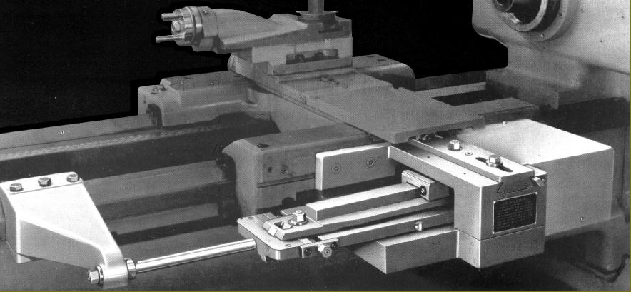
"Powerturn" Rapid feeds attachment with built-in over-load clutch. The makers also listed a different system with a powershaft running down the back of the bed.
|
|
|
|
|
|
|
 |
|
|
|
|
|
|
Taper Turning Attachment on the "Powerturn" models
|
|
|
|
|
|
|
|
|
|
|
|
|
|
|