 |
|
|
|
|
|
|
|
|
|
|
|
|
|
|
|
|
|
|
|
|
|
|
|
|
|
|
|
|
|
|
|
|
|
|
|
|
|
|
|
|
|
|
|
|
|
|
|
|
|
|
|
|
|
|
|
|
|
|
|
|
|
|
|
|
|
|
|
|
|
|
|
|
|
|
|
|
|
|
|
|
|
|
|
|
|
|
|
|
|
|
|
|
|
|
|
|
|
|
|
|
|
|
|
|
|
|
|
|
|
|
|
|
|
|
|
|
|
|
|
|
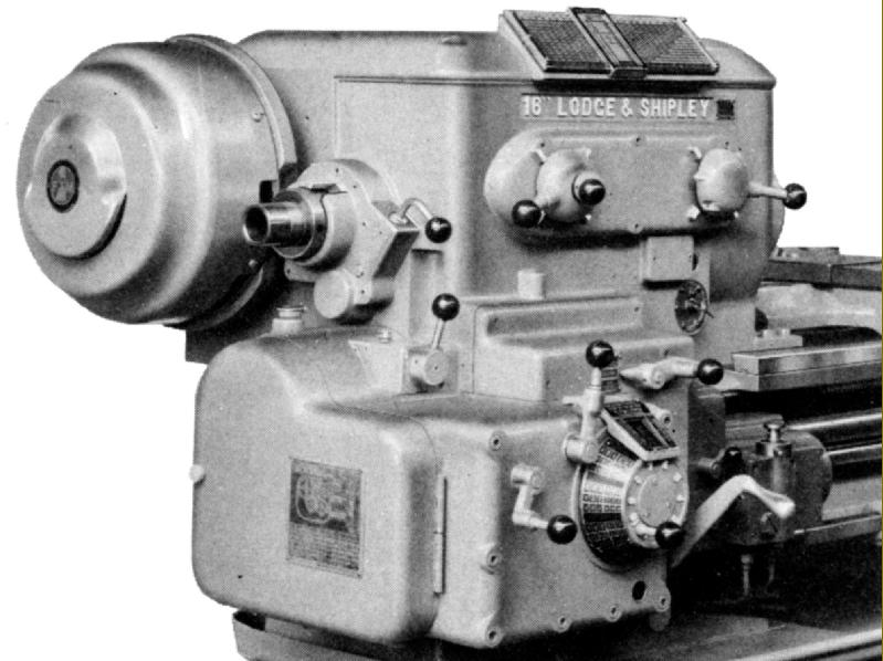
Introduced in the 1940s Lodge & Shipley Model X lathes were typical of the Company's products: serious, very heavily built and carefully-considered designs that took full advantage of the latest developments in metallurgy and turning tools. Quality inspection was an important part of the Lodge and Shipley approach to machine-tool building and each department in the factory retained independent inspectors, answerable to the chief inspector, but also with a particular emphasis on the role of the foreman - whose responsibility was to ensure that the highest standards of workmanship were properly maintained by the workforce.
The X Series lathes were built in several sizes and four versions: Engine (also listed in catalogues as "Standard"), Manufacturing, Toolmaker and Oil Country. "Engine" and "Manufacturing" models were available with swings of 14", 16", 20" and 25" as Heavy Duty models and with 20" and 25" swings as Medium Duty types. The "Toolmaker" could be had with 14", 16" and 20" swings as a Heavy Duty or with a 20" swing as a Medium Duty. The special big-bore Oil Country lathes were available only in a 25" size - but as a Heavy Duty Model with an 11.5" bore spindle, or a Medium Duty Model with a 5.875" bore.
Continued below:
|
|
|
|
|
|
|
|
 |
|
|
|
|
|
|
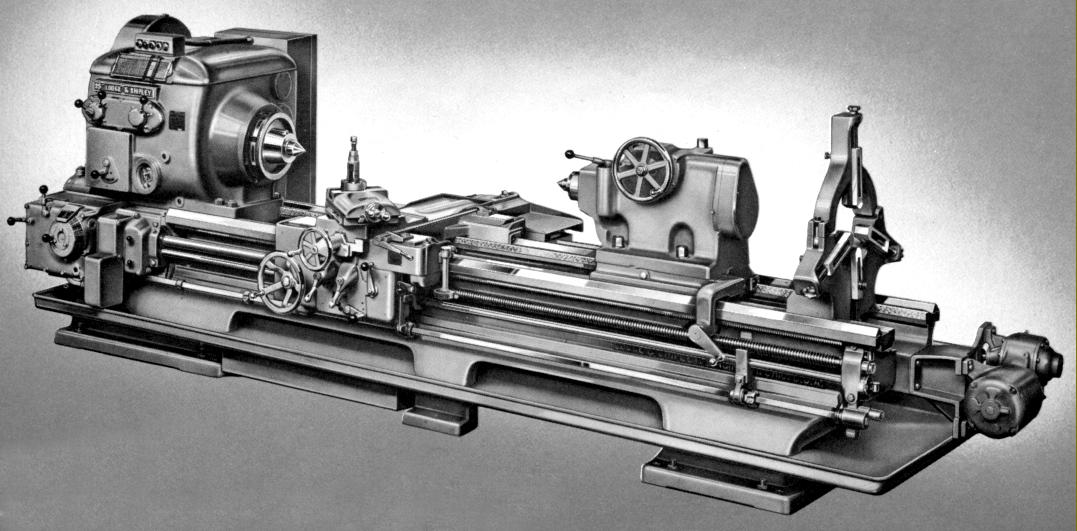
Lodge & Shipley Model X Engine Lathe with mid-bed support foot & rapid carriage return
Continued:
Designed for a long and reliable life the headstock on each model was given a range of 24 forward and 16 reverse speeds appropriate to its size and intended function: on the 14" and 16" Heavy Duty and 20" Medium Duty lathes three speed ranges were available: Standard, Intermediate and High: theses were, respectively: 14 to 1160 r.p.m.; 21 to 1740 r.p.m. and 24 to 2000 r.p.m. The 20" Heavy Duty and 25" Medium Duty models had two ranges, Standard and High, respectively: 9 to 500 r.p.m. and 13.5 to 752 r.p.m. whilst the largest machines, the 25" Heavy Duty and 32" Medium duty, could run from7.5 to 422 r.p.m. in Standard range or 9 to 507 r.p.m in High.
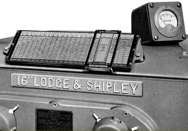
An ammeter could also be provided to let the operator check that, for a given job, the machine was being run to its maximum capacity, yet not being overloaded - a comprehensive headstock-mounted chart, with a sliding-line indicator, being provided to furnish the correct both information about the maximum h.p. that could be used at lower r.p.m. together with the optimum setting for work of a particular diameter. With such a wide range of speeds available, from usefully low to very high, it was possible for one machine to undertake a wide variety of tasks from the machining of small components to the turning of large castings on a faceplate - and careful low-speed thread cutting. Headstock gears were either hardened and then tooth-profile ground or, depending upon their function, shaved after gear cutting and then flame hardened. The headstock layshafts were hardened, with ground splines, and all ran in ball or roller races. Manufactured from nickel-chrome steel the headstock spindle had a hardened nose of the American long-nose taper in a size according to its centre height - the spindle being assembled into the headstock before its taper bore was finally ground to ensure absolute concentricity with the bed. The spindle clutch was operated by control levers duplicated on the carriage and next to the screwcutting gearbox - and the spindle brake was applied automatically as the clutch was withdrawn. Headstock gears were naturally of high quality: precision-shaved and hardened spur gears running on hardened and ground shafts all turning in anti-friction bearings. Lubrication was automatic and under pressure - a centrifugal pump lifting oil from a separate reservoir though a replaceable 'Purolator' automotive-type cartridge filter to the headstock from where it was directed by an "oil spinner" and distribution tray connected to a number of feed pipes. By sending oil back to a separate container (and so removing much of the heating effect from gears churning it round) a more uniform temperature was maintained throughout the headstock.
Continued below:
|
|
|
|
|
|
|
|
 |
|
|
|
|
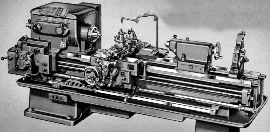
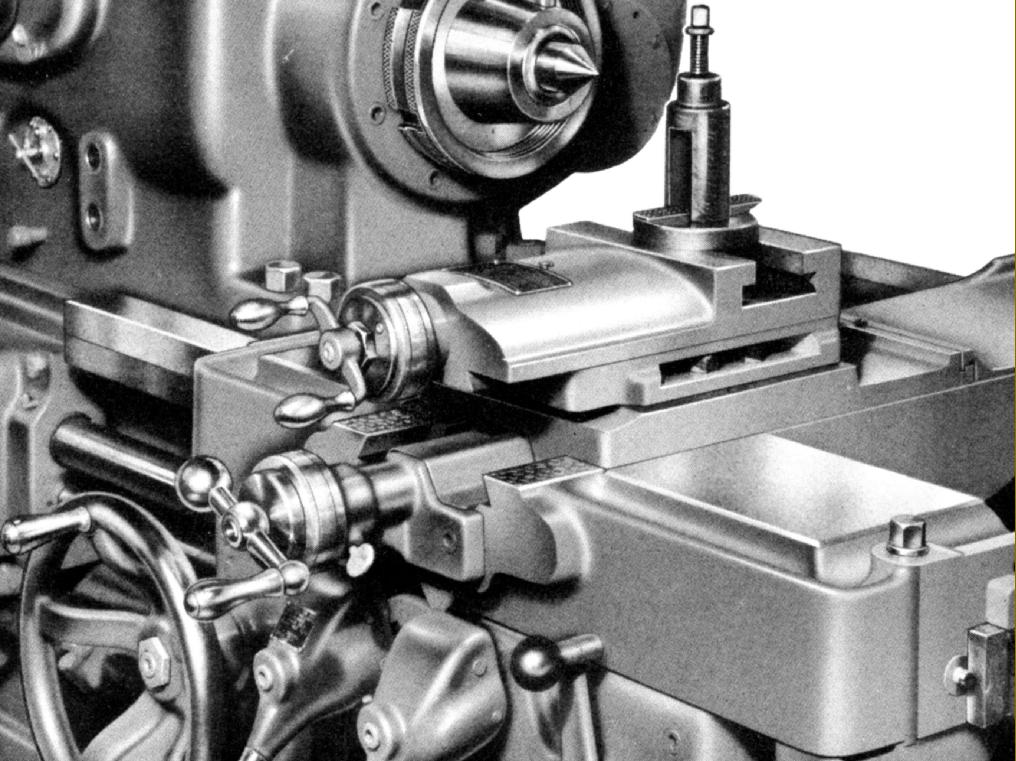
Lodge & Shipley Model X Manufacturing Lathe. Note the multi-stops of the cross feed
|
|
|
|
|
|
|
|
|
Continued:
All models had massive beds with the "trade mark" Lodge and Shipley elliptical webs between the front and back walls. According to factory tests the design was superior to conventional "saw-tooth" or rectangular webbing and, having been patented, was an exclusive feature of the company's lathes for many years. However, an examination of a Colchester bed will reveal a design not altogether dissimilar. The hardened and ground outer bed ways were in hardened steel but, being tongued and grooved into the bed, and retained by bolts, could be replaced with relative ease. The ways were not the traditional American V-type, but of rectangular form with the front having an "inner" V to absorb tool thrust.
Massively constructed, the carriage had a deep and rigid saddle with long, equal-length at each side. This construction placed the cross slide on the saddle centre line, where it was best supported - the bed ways being arranged so that the carriage could slide partially past the headstock to bring the toolpost right up to the spindle nose. The saddle was aligned to the bed using what the makers termed "sustained alignment" - meaning simply that the full length of the saddle was in contact with both front and rear bed ways - with adjustment of the sliding fit by long tapered gib strips against the front outer vertical bed surface together with a tapered gib under the rear of the saddle to eliminate lift. In order to reduce twisting and other misalignment forces, both the rack-and-pinion carriage hand drive, and the leadscrew clasp nuts, were aligned with the front bed way. Made in two halves spigoted together - and with the front section detachable without further dismantling, or even removing it from the lathe - the apron used heat-treated alloy steel gears running on shafts supported at each end and turning in ball races. Instead of the usual friction clutches to engage the power sliding and surfacing feeds "X" lathes employed ones with positive "saw-tooth" engagement, a design claimed by the makers to be free from sticking, maintenance-free and yet able to give an easy yet positive engagement. In order to reverse the sliding or surfacing feeds on the Engine and Toolmaker lathes it was not necessary to alter the direction of rotation of the changewheels; instead, a lever on the apron accomplished the same task by engaging one or other of a pair of pinions set at each side of the apron-mounted crownwheel.. On models not fitted with the apron-mounted reverse a lever-operated mechanism was built into the headstock. Control of the carriage stop and start was through a square-section control rod with two operating levers - one on apron and the other by the screwcutting gearbox. All Model "X" lathes had two adjustable automatic length stops, one for each direction of carriage travel, that operated both when screwcutting and using the power sliding feed. However, the "Manufacturing" model was fitted with a special system, able to stop the power-sliding drive (but not screwcutting) in up to 5 positions one after the other when the carriage was moving towards the headstock. The trips slid on a separate bar, bolted to the bed, and when one trip had operated the turner was able, if very accurate results were needed, to move the carriage a little further by hand against a second positive stop before re-engaging the drive. A most useful standard fitting on the Toolmaker version was "reverse to the leadscrew", a system that allowed the spindle to continue running and the clasp nuts to stay engaged - hence completely obviating the need to refer to the thread-dial indicator when screwcutting. Although limited to spindle speeds under 400 r.p.m. leadscrew reverse was not only useful when cutting standard threads, but a tremendous help when it was necessary to generate metric or odd threads and leads - or on similar occasions when the thread dial could not pick up the engagement point. The mechanism was simple and involved an additional control rod, parallel to the leadscrew that, when partially turned by its operating handle, shifted a single-tooth "dog-clutch" mechanism contained within the changewheel drive to the screwcutting gearbox. Of course, on lathes without leadscrew reverse it was still possible to cut odd pitches and metric threads by the usual method of leaving the claps nuts engaged, withdrawing the cutting tool, and then electrically reversing the machine back to the starting point of the thread.
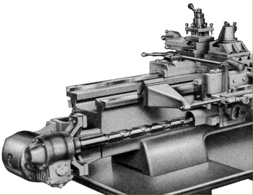
A four-way power-feeds rapids unit was available and used a separate motor driving, through worm-and-wheel gears and a multi-disc overload clutch, a reduction gearboxes bolted to the tailstock end of the bed. A separate shaft, running down the back of the bed, passed through left and right-hand bronze nuts carried in a housing attached to the back of the carriage. An independent control unit, operated by a lever on the front face of the apron, enabled either nut to be restrained and rapid traverse of sliding and surfacing feeds selected in either direction. Pressing the handle operated the feed whilst releasing it caused an instant return to neutral and immediate disconnection of the drive.
Lubrication of the apron was automatic with a built-in plunger pump operated by cams on the cross-feed and longitudinal-feed clutch shafts during any movement of the carriage or cross slide. A supply of filtered oil was distributed not only around the apron internals but also to the front and rear bed ways and the cross and top-slide ways. The pump could also be operated manually by a lever, a useful fitting when the carriage was stationary and the top slide in continuous use - or if the lathe had stood unused for some time.
Continued below:
|
|
|
|
|
|
|
|
|
|
|
|
|
|
 |
|
|
|
|
|
|
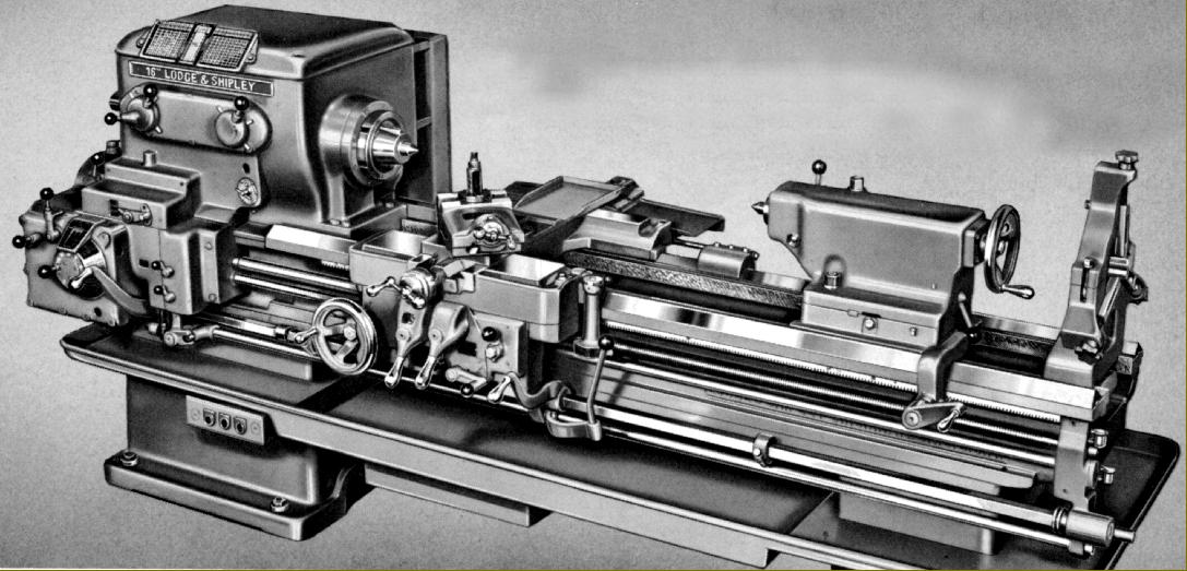
Lodge & Shipley Model X Toolmakers' Lathe
|
|
|
|
|
|
|
|
|
Continued:
Of unusual design, the cross and top slides used taper gib strips and ran on ways of inverted dovetail form that were intended to both improve swing over the compound and yet aid rigidity. The 360° swivel top slide had a square base that reduced tool overhang and providing a firm foundation - no matter how acute the set-over angel. The rear of the cross slide, normally fitted with a chip shield, was machined to accept the optional taper-turning unit and also allow the mounting of an extension slide to mount rear toolposts or other fittings. The flame-hardened cross slide screw was of the telescopic type - allowing a taper-turning unit to be fitted without the need for any alterations - and ran though double compensating bronze nuts adjustable to eliminate backlash. It also incorporated a very useful micrometer ball stop of the kind used on earlier machines.
On smaller models of the X range the top slide screw was driven by a 1 : 1 gear arrangement that allowed a step-up end bracket to be used - so giving clearance above the cross-slide handle and micrometer dial.
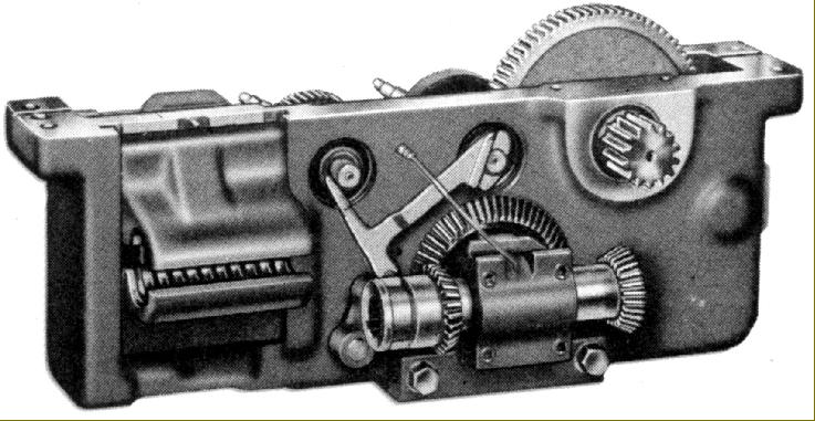
Offering what the makers called "Fingertip Control of Threads and Feeds" the screwcutting gearbox was completely enclosed, pressure lubricated and provided with simple, easy-to-use rotary and lever controls. It was a typical Lodge and Shipley mechanism containing the usual high-quality components: hardened and shaved gears and hardened shafts running in anti-friction bearings. 55 pitches and rates of feed were available without the need to dismount or replace any of the changewheels and when fitted with the necessary translation wheels an English screwcutting gearbox could generate a full range of 55 metric pitches, and a metric lathe 55 English threads. On both English and metric machines module and diametral pitches could also be generated by the substitution of appropriate changewheels. Sliding and surfacing feed rates varied from 0.00075" to 0.187" (0.0019 to 0.476 mm) per revolution of the spindle whilst English pitches went as high as 256 t.p.i. The design of the gearbox and its operation were interesting - and removed the need for the operator to struggle with a reluctant-to-shift tumbler lever. This was achieved by separating the sliding tumbler gear selector from the fixed cone of gears by the use of clever "alligator" jaws. When the jaws were opened - by a lever on the left of the box - the tumbler could be moved sideways by rotating a dial, marked with the various thread positions and working through a pinion, segment lever and fork assembly. When the desired pitch was indicated on the dial the jaws lever was closed, so engaging the gears and ensuring that they meshed correctly. Two other levers, to the right of the rotary dial, were juxtaposed to complete the sequence necessary to select the full range of pitches and feeds. Lubrication was positive, with oil lifted from the base of the gearbox by a plunger pump and sent to a distribution plate from where it was directed to the gears, shafts and their bearings - and also to the leadscrew and powershaft support bearings. The leadscrew, made from a special ground alloy steel and precision chased on a special lathe, was tensioned between precision thrust bearings.
With automatic lubrication from an oil reservoir built into its base, the tailstock was moved along the bed by a crank handle working gears that picked up on the bed carriage rack. The spindle was made from heat-treated, hardened and ground steel and fitted with a ball race thrust bearing. On the smaller models clamping to the bed was achieved by two bolts at the front and a single, cam-operated bolt at the rear - whilst for the 20-inch and larger machines double clamping by bolts was used in both locations..
|
|
|
|
|
|
|
|
 |
|
|
|
|
|
|
Lodge & Shipley Model X Engine Lathe with gap bed
|
|
|
|
|
|
|
|
 |
|
|
|
|
|
|
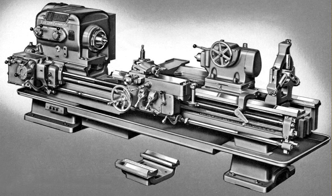
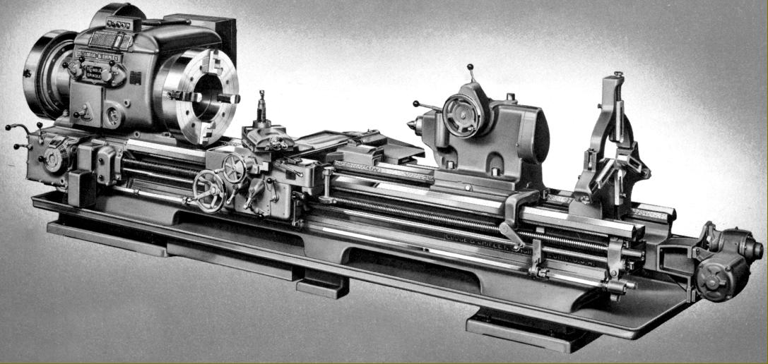
Lodge & Shipley Oil Country Model X lathe with large spindle bore
|
|
|
|
|
|
|
|
 |
|
|
|
|
|
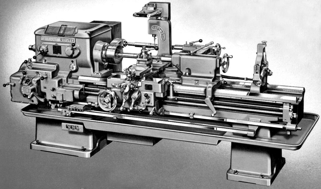
Lodge & Shipley Model X lathe with "Copymatic" copying equipment
|
|
|
|
|
|
|
|
 |
|
|
|
|
|
|
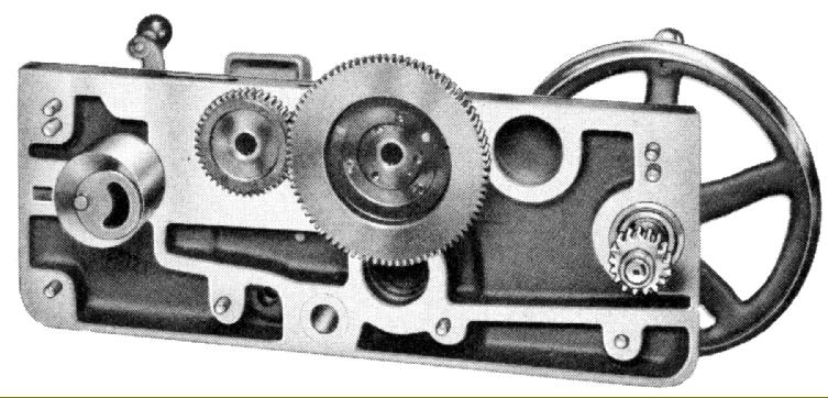
A view of the apron "peeled" open. Made in two halves spigoted together (note the dowels) the front section could be detached without further dismantling, or even removing it from the lathe.
|
|
|
|
|
|
|
|
 |
|
|
|
|
|
 |
|
|
|
|
|
|
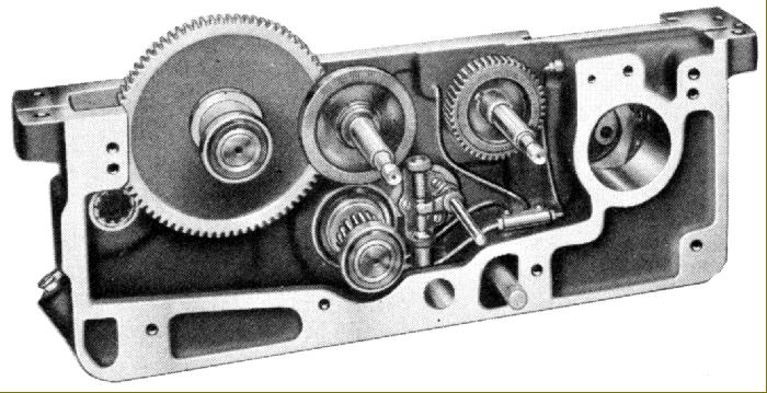
Rear view of assembled apron showing the crown-wheel and pinion gearing that enabled instant reverse for the power feeds
|
|
|
|
|
|
|
|
 |
|
|
|
|
|
|
A clear view of the "inverted" cross-slide ways
|
|
|
|
|
|
|
|
 |
|
|
|
|
|
|
A four-way power-feeds rapids unit was available and used a separate motor driving, through worm-and-wheel gears and a multi-disc overload clutch, a reduction gearboxes bolted to the tailstock end of the bed. A separate shaft, running down the back of the bed, passed through left and right-hand bronze nuts carried in a housing attached to the back of the carriage.
|
|
|
|
|
|
|
|
 |
|
|
|
|
|
|
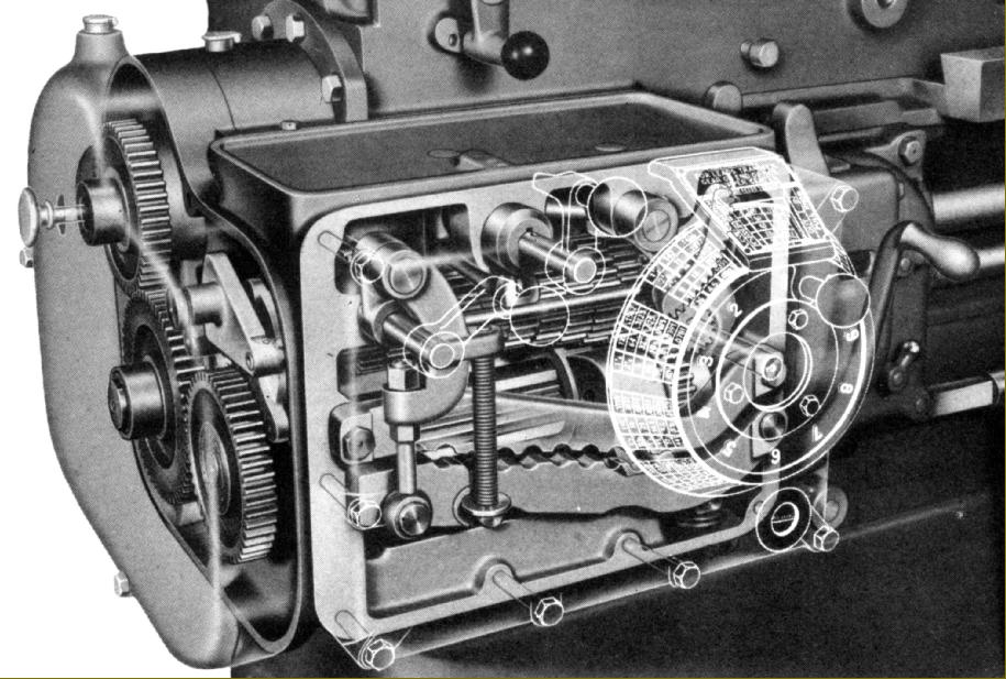
Speeds and feeds calculator
|
|
|
|
|
|
|
|
 |
|
|
|
|
|
|
A view into the unusual screwcutting and feeds gearbox. In this illustration the alligator jaws are closed and the gears meshed.
|
|
|
|
|
|
|
|
 |
|
|
|
|
|
|
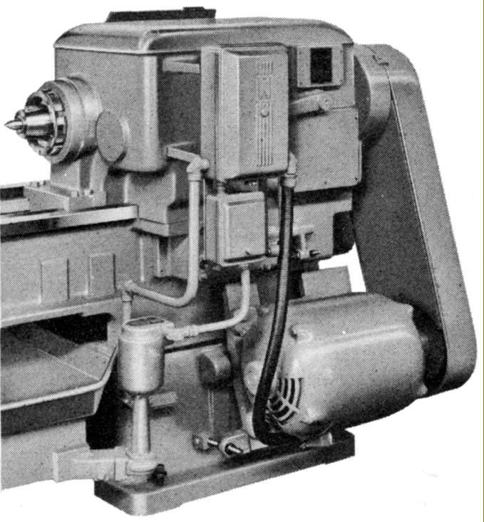
Individual motor drive. Quickly adjustable and easily reached for maintenance
|
|
|
|
|
|
|
|
 |
|
|
|
|
|
|
Another option was a compact flange-fitting "pancake" motor - though this could only be supplied in a limited number of lower-powered ratings
|
|
|
|
|
|
|
|
|
|
|
|
|
|
|
|