|
|
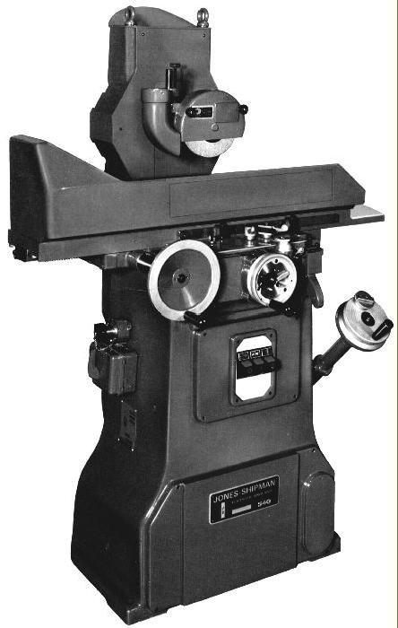
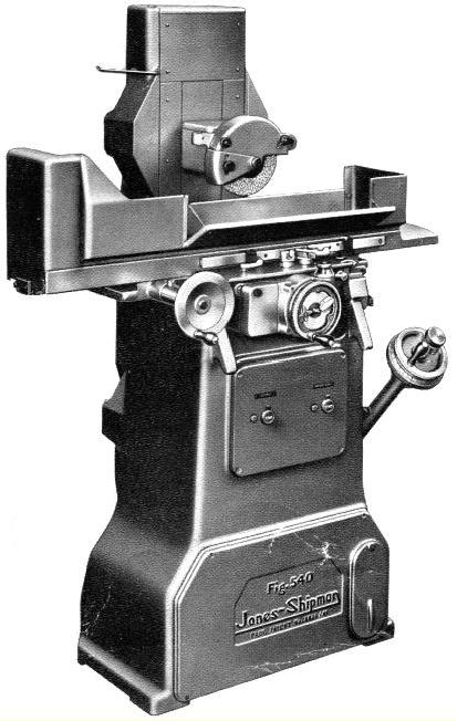
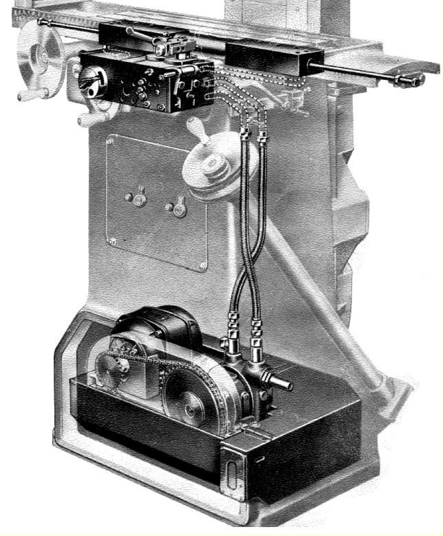
First manufactured during World War Two, in 1941, the Jones & Shipman 540 surface grinder was to become the company's most widely sold individual type with over 25,000 examples made. In comparison to many similar grinders the 540 was particularly easy and comfortable to use, many toolroom employees telling the writer that, of all the types at their disposal for smaller work, it was their model of choice. Its design was based on the general arrangement and capacity of the 1930s American Brown and Sharpe Model No. 2 - itself a very popular and widely exported machine. Although the Brown & Sharpe used a mechanically driven table, from the outset the 540 employed the hydraulic power as seen earlier on the 540's predecessors, the Types 608 and 450. At a stroke the use of oil-driven slides greatly reduced production costs - by eliminating whole trains of gears - enhanced reliability and gave the machine a reputation for having an absolutely smooth, steady table movement that did much to ensure a particularly fine surface finish and improve accuracy. Although the 540e was altered in detail over the years - the appearance cleaned up, more powerful motors fitted, feed rates altered, the appearance of the control levers and dials modernised and electronics fitted - its major components remained virtually unchanged and a testimony to the skill of the original designer.
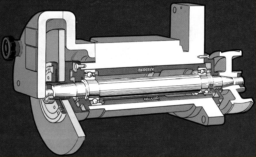
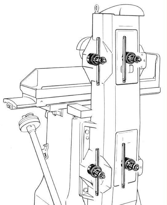
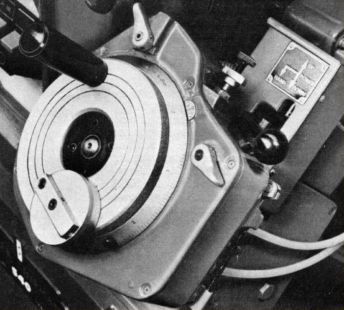
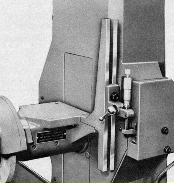
Occupying a floor space of just 65" x 32.5 inches ( 1650 x 825 mm) and with an 18" x 6" (450 x 150 mm) table capable of moving 19 inches (480 mm) longitudinally and 6.75 inches (170 mm) in traverse the 540 grinder was ideally suited to most smaller toolroom jobs. The table ran on a V and flat way and, although highest feed rate on early types was set at 40 feet per minute, the vast majority can be set to run at between 5 and 60 feet per minute (1.5 to 18 mm). The cross slide was supported on two V ways with a feed rate of 0.007" to 0.07" (0.175 to 1.75 mm) per minute at each reversal of the longitudinal stroke. However, early machines had a very much coarser feed, from 0.01" to 0.07" (0.25 to 1.75 mm) - though in practise these are entirely satisfactory for the majority of jobs. The head had a vertical travel of 11 inches (280 mm) and the depth of the largest work piece that could be accommodated on the table (assuming the use of a standard 7-inch (178 mm) diameter grinding wheel) was 9.5 inches ( 240 mm). In later years the option of an extended height column was offered (Model 540L) , this allowing version allowing some 16 inches (406 mm) clearance beneath the wheel. Both the cross-feed and vertical-feed micrometer dials were graduated in increments of 0.0001" (0.0025 mm). With a 50 cycle motor the wheel rotated at 3,000 r.p.m. and on 60 cycles (for the American and other markets) 3.600 r.p.m. The 540 was, like all other J & S grinders of the 1940s, fitted with a super-precision plain-bearing spindle. However, from the early 1950s, the option a ball-bearing supported spindle had been offered and, from the late 1960s this type (being cheaper to produce) became standard. To placate customers who considered the plain-bearing type to be smoother-running this could still be ordered, but at extra cost. The plain-bearing spindle required lubricating with Mobil Velocite No. 3 (or an equivalent) and was intended to run at a temperature of either 38 centigrade above ambient or at 62 centigrade, whichever was the lower. The oil temperature was measured by inserting a thermometer through the oil filler cap on the top of the wheelhead. Each slideway - and the hand-traverse wheel bushings - were lubricated automatically from the hydraulic oil supply, though if prolonged hand use was undertaken the makers cautioned against running with the pump motor switched off--when no oil would be circulated and the slides damaged.
By the late 1960s the 540 was being fitted with more powerful motors - a 2 h.p. main replacing the 1 h.p. original and that driving the hydraulic pump being upgraded from 0.5 to 0.75 h.p. A version with a greater vertical capacity was also introduced, the 540L. This used a lengthened main column allowing a larger diameter, 9-inch wheel to be fitted and, with greater clearances, taller jobs to be mounted on the table.
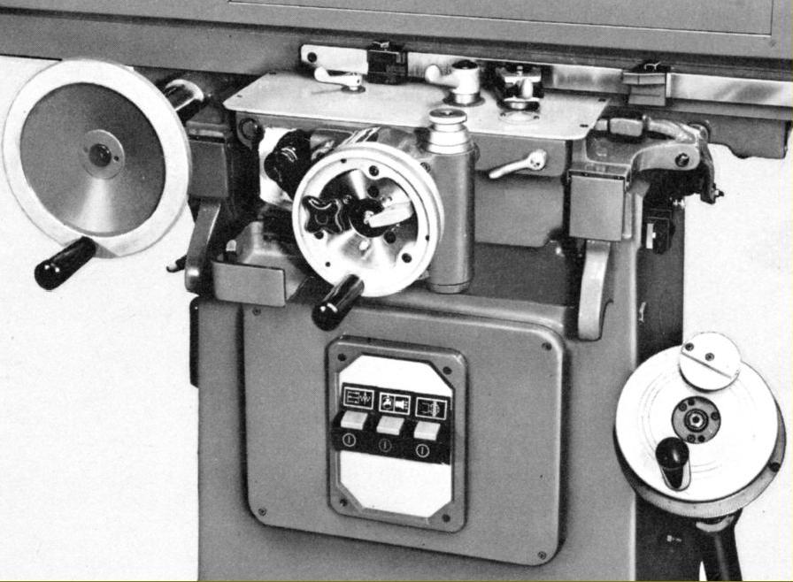
Options:
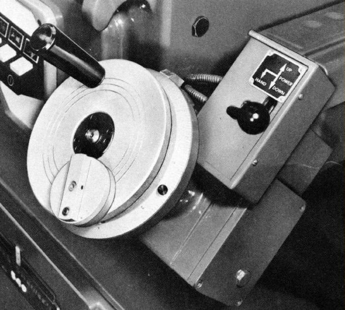
A popular addition was power rise and fall to the head (Model 540P) - though this is often found with a further extra (it could not be incorporated separately) - automatic downfeed to the head (Model 540PF). Fitted with these units the vertical feed adjustment micrometer dial was engraved at intervals of 0.00005" (0.001 mm) with the automatic feed rate adjustable between 0.00005" and 0.0003" (0.006 mm) per pass.
Accessories:
In addition to the usual dust-extraction and coolant units a wide range of useful accessories was eventually to be made available including: a Wheelhead-mounted Wheel-dressing Attachment; a High-speed Grinding Attachment; a Precision Circular Grinding Attachment - mounted on an inclinable sine platform and a 13,000 r.p.m. Vertical Grinding Unit - able to be swivelled up to 10-degrees in either direction. In addition various accessories by third-part suppliers was offered: the "Mayform" self-contained, Motorised Cylindrical Attachment complete with tailstock; ; a "Bowers" Inclinable Rotary Table unit - mounted on a sine table and with a self-contained motor, gearbox and drive unit that enabled circular components to be rotary ground at angles from 0 to 45 degrees whilst under the "Diaform" brand three popular additions were the Head-mounted Wheel-forming Attachment and the Tangent/Radius and Radius/Angular wheel-forming units. Profile grinding was also possible using the "Copiform" Surface/Profile device where a stylus traversed over a template by manipulating the cross traverse and rise and fall movements of the machine whilst maintaining "zero" on the indicator to which the stylus was attached..
|
|