|
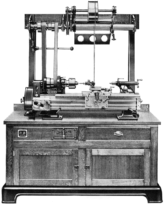
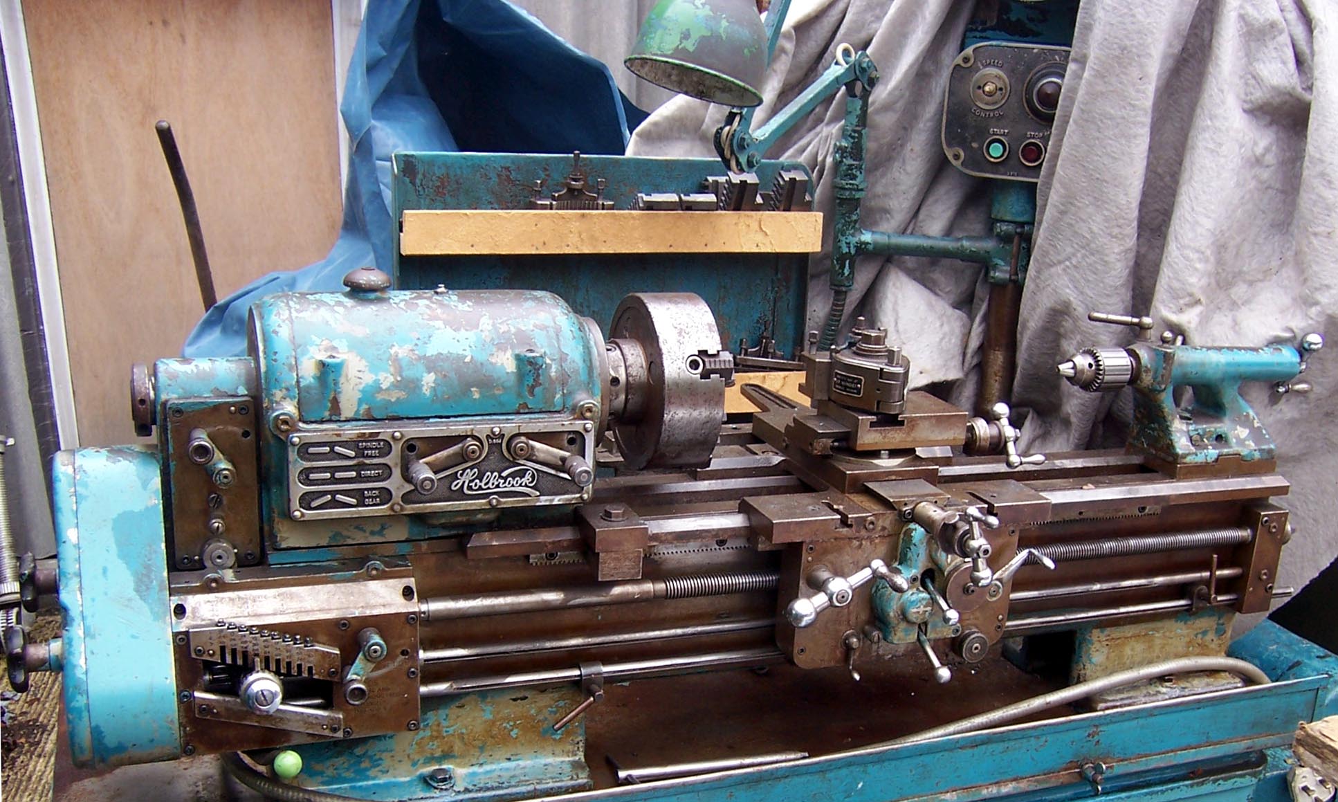
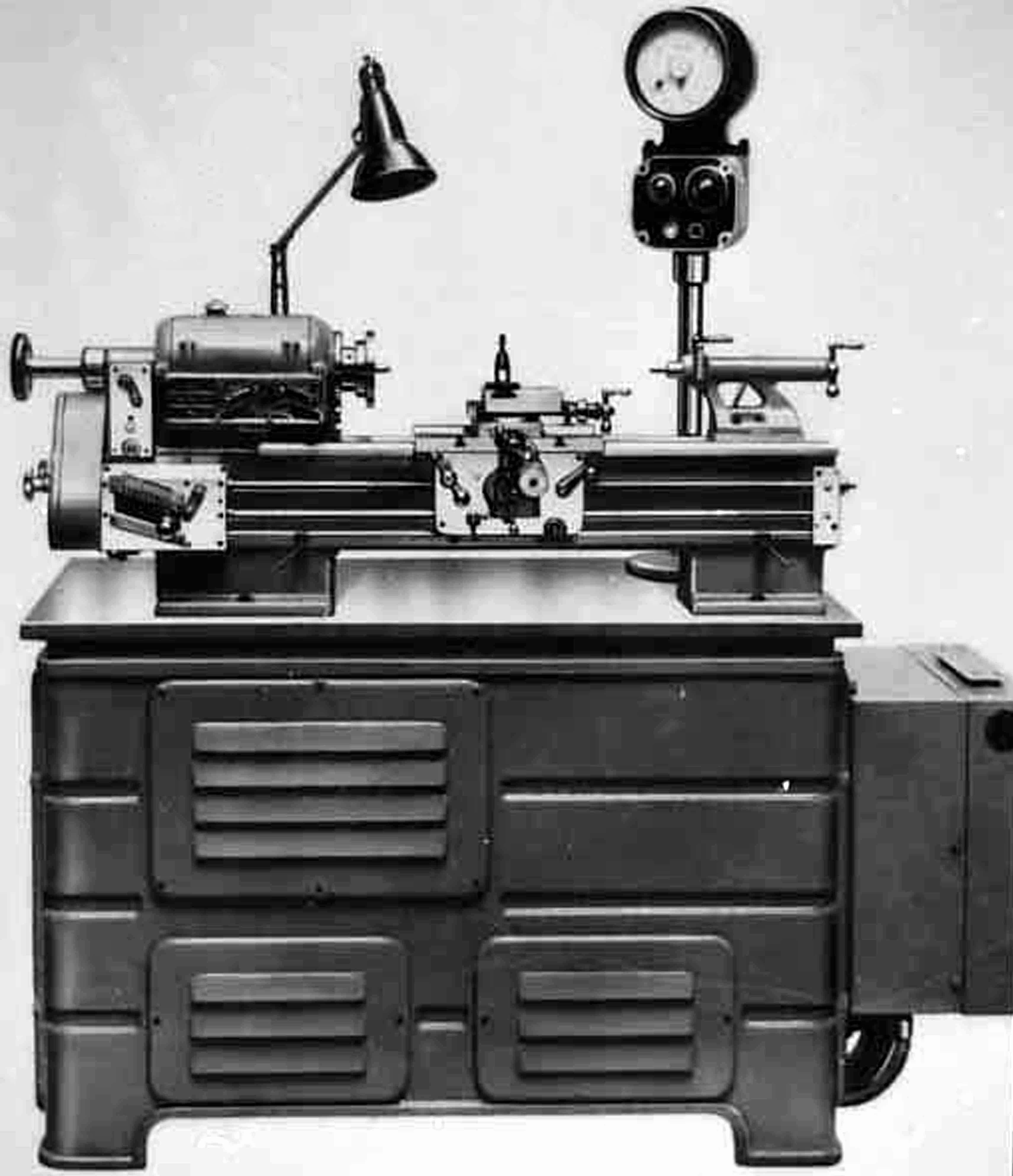
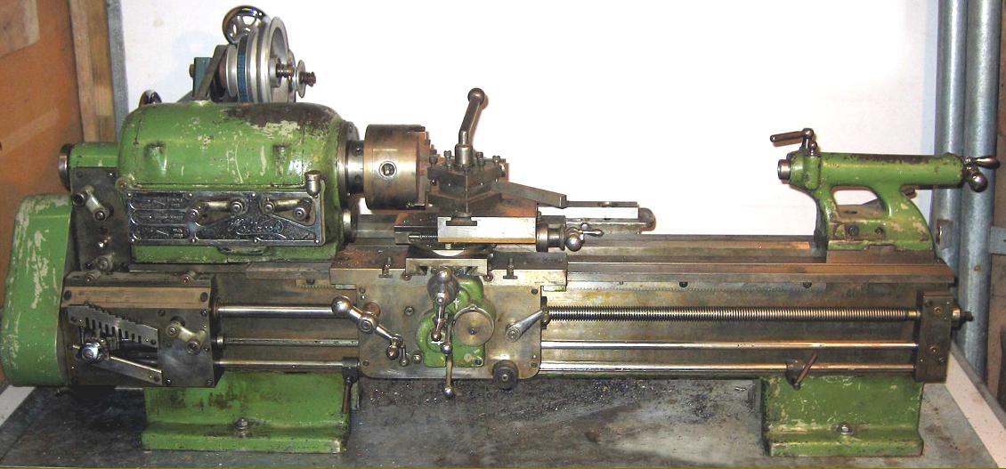
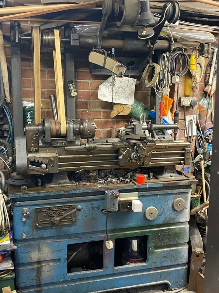
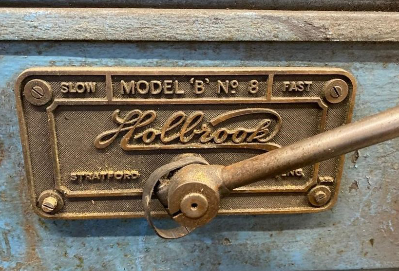
Holbrook Lathe Model B No. 8 4" centre height and 20" between centres.
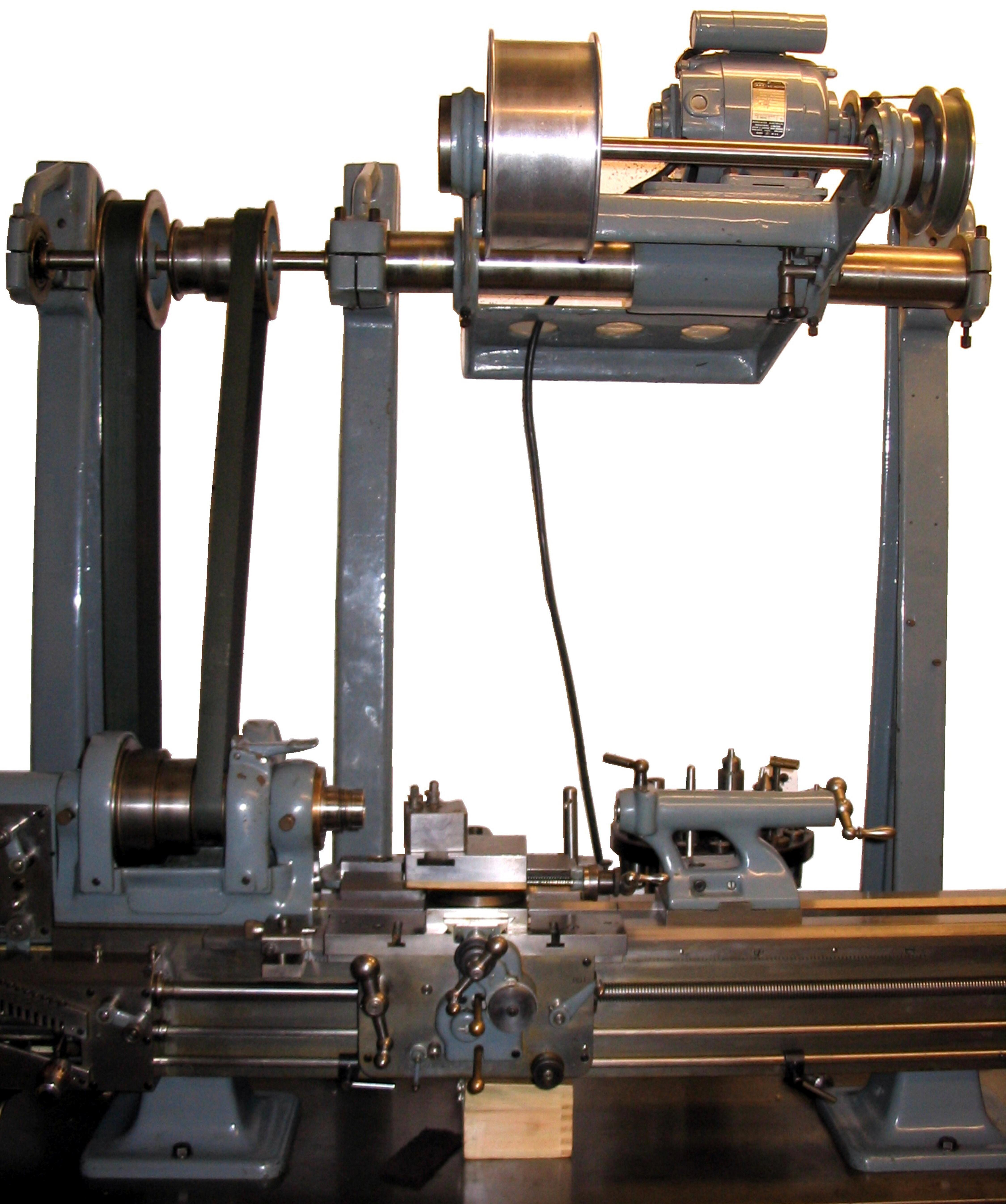
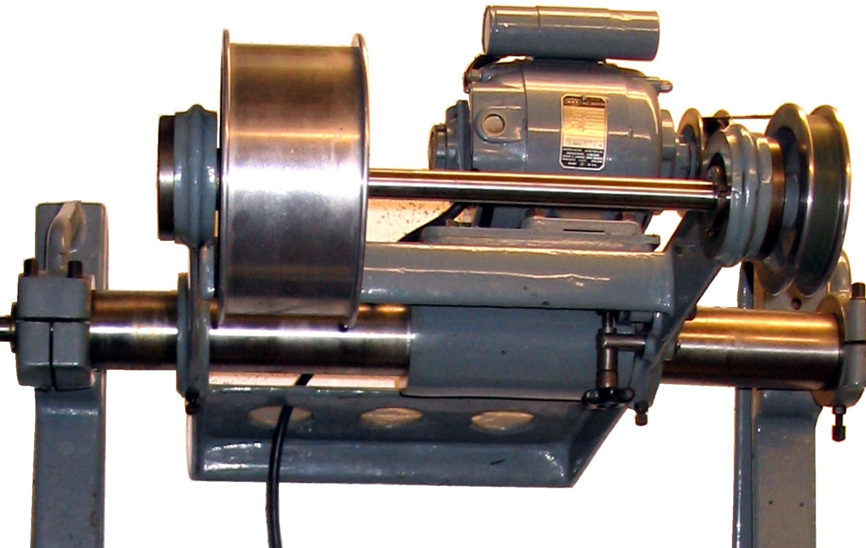
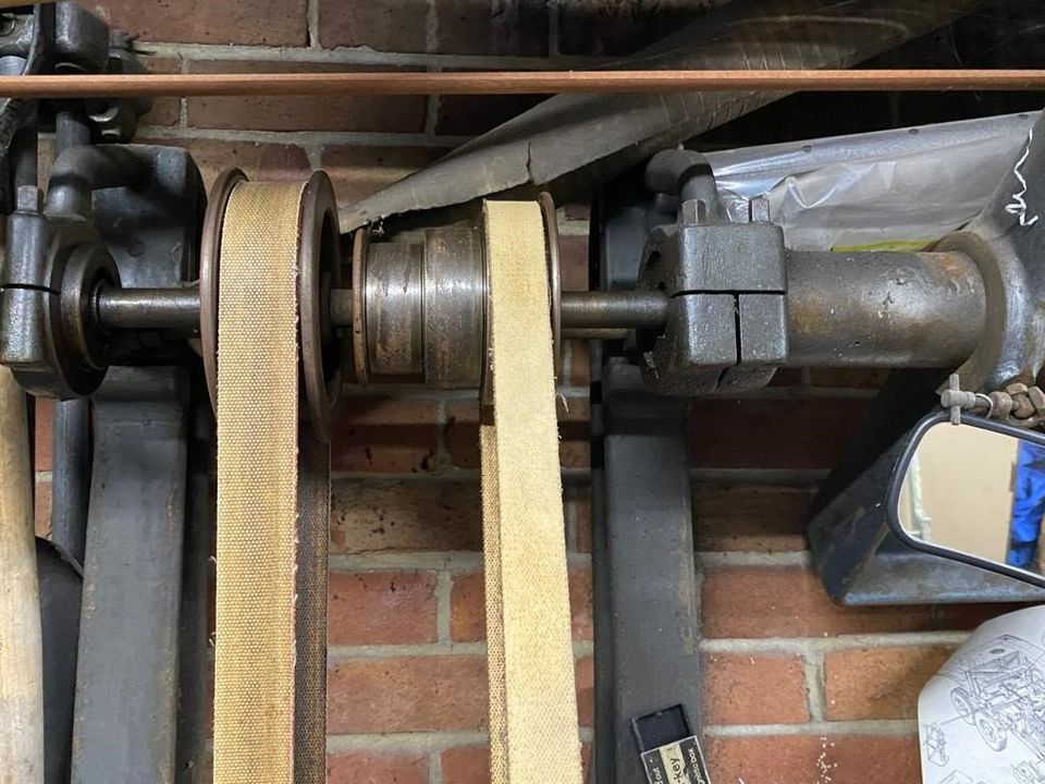
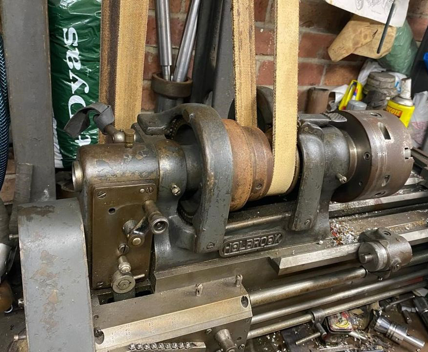
Shown fitted to one of the optional stands (the optional polished-oak cabinet stand, itself mounted on a cast-iron base) this beautifully made and highly desirable Holbrook lathe had detail touches that bore a passing resemblance to certain features of the superb American Rivett 608 precision toolroom lathe. This superb stand, besides mounting a push-button starter and a lever switch for the two-speed electric motor, also incorporated an optional, self-contained, ball-bearing overhead drive to power grinding and milling spindles held in the toolpost - the lathe above is shown with a grinding head so mounted.
Machined from an aged casting, the very deep and heavily-constructed bed (it was considerably deeper than the lathe's centre height) had the whole of its outer surfaces (in the manner of Rivett lathes) form milled and then ground and hand scraped to provide a wonderful cosmetic finish. A single rear V-way located the headstock with another, at the front of the bed, combining to guide the carriage.
With a standard-fit, two-speed motor and clutch drive, together with the 6.8 to 1 ratio backgear, a range of 12 speeds spanning 43 to 1340 rpm was provided. The hardened and ground spindle was bored 7/8" - though both it, and the tailstock barrel, carried inadequate No. 1 Morse tapers - a failing typical of the time. A set of draw-in collets, with a maximum capacity of 5/8" (or the metric equivalent) was provided with the lathe - as was a hand-operated, headstock-mounted brake to slow the spindle from high speeds.
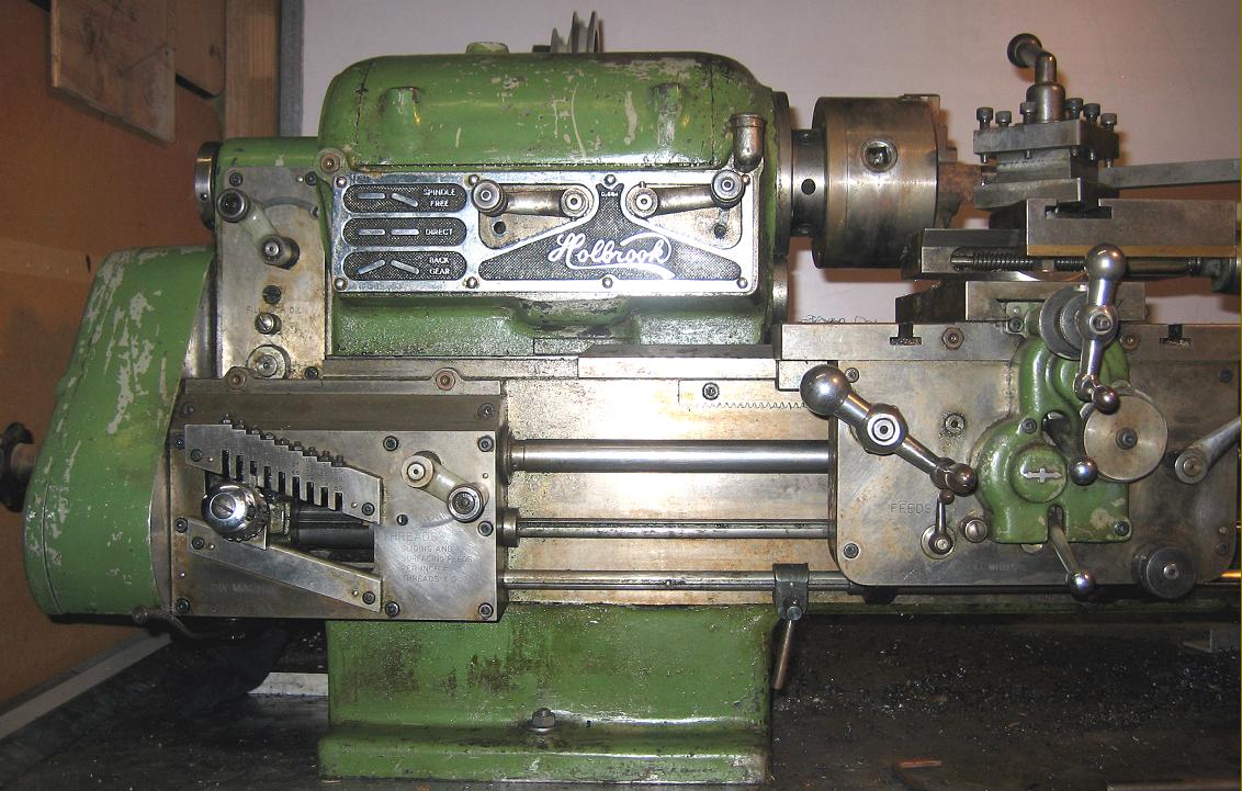
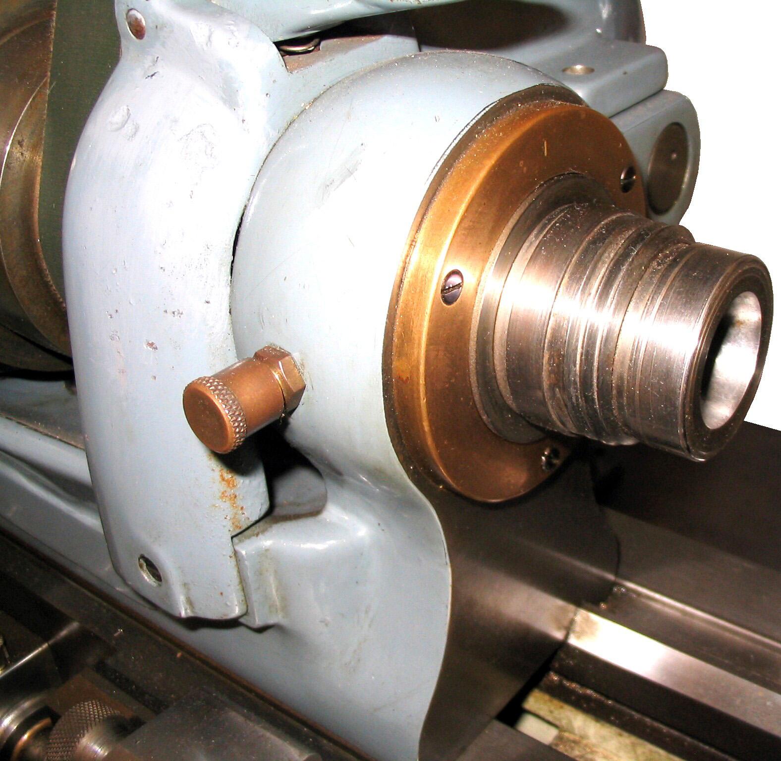
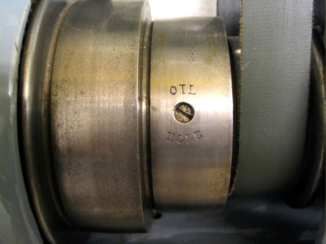
Equipped with a 1.75" B.S.F. nose thread (British Standard Fine) the spindle was lapped to its tool-steel cone bearings that had both internal and external tapers - the design incorporating a simple, foolproof method of adjustment. The front bearing had a double-step taper with one part, set at 45 degrees, designed to take spindle end thrust in in one direction - while at the back of the bearing took the thrust in the opposite direction. By using this construction the makers claimed to have limited the effects that temperature changes, caused by heavy-duty turning, had on the spindle's length. The threaded nose was fitted with registers at front and back - an idea intended to improve the rigidity of the mounting, but one that found favour with few other makers, through the English firm Cromwell did use it on their toolroom lathe. A conventional, rear-mounted backgear was fitted together with a (rather ineffective) spindle brake operated by a short, press-down handle on top of the headstock. The spindle bull-wheel was ringed with 60 indexing holes.
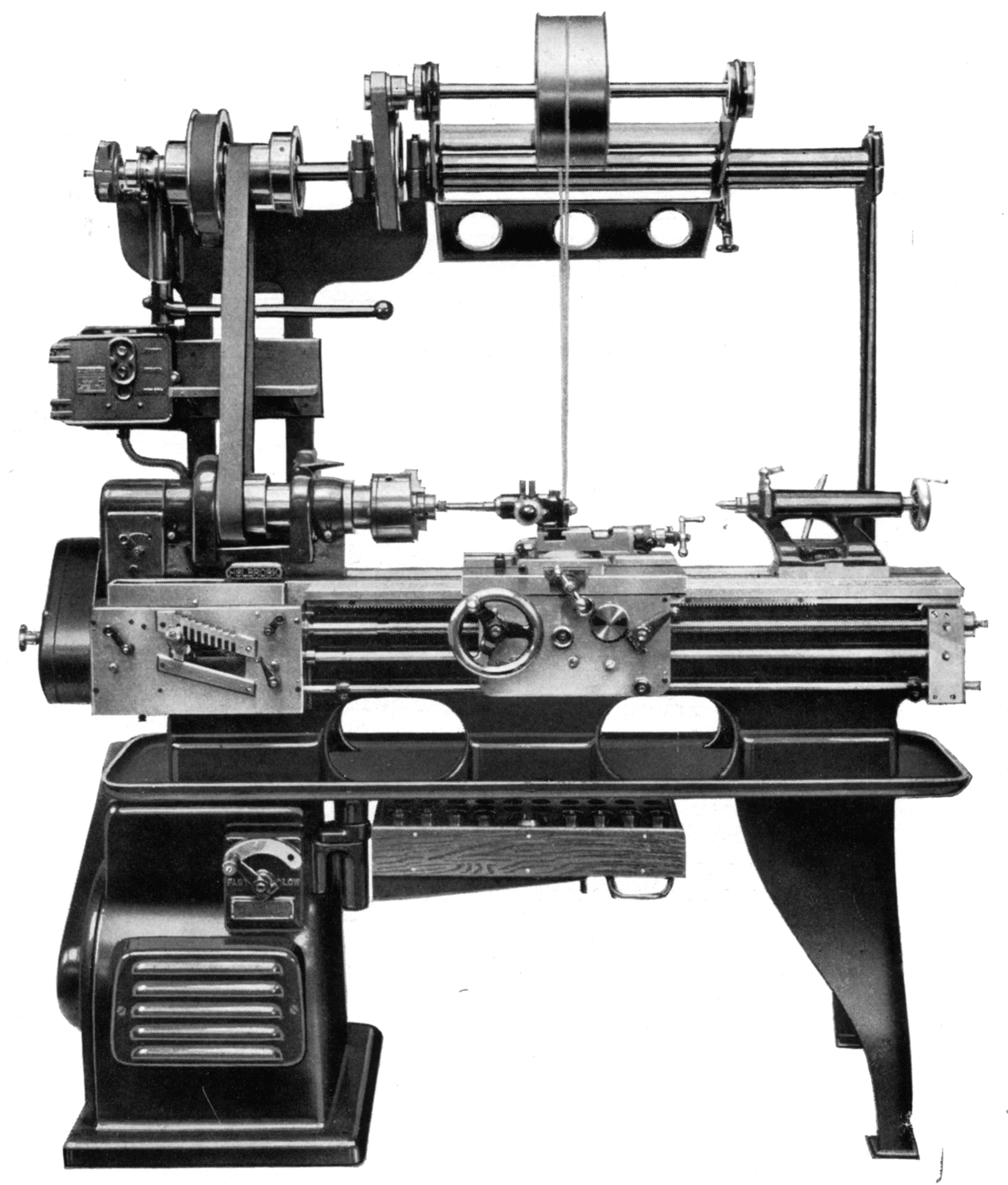
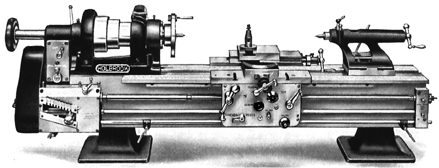
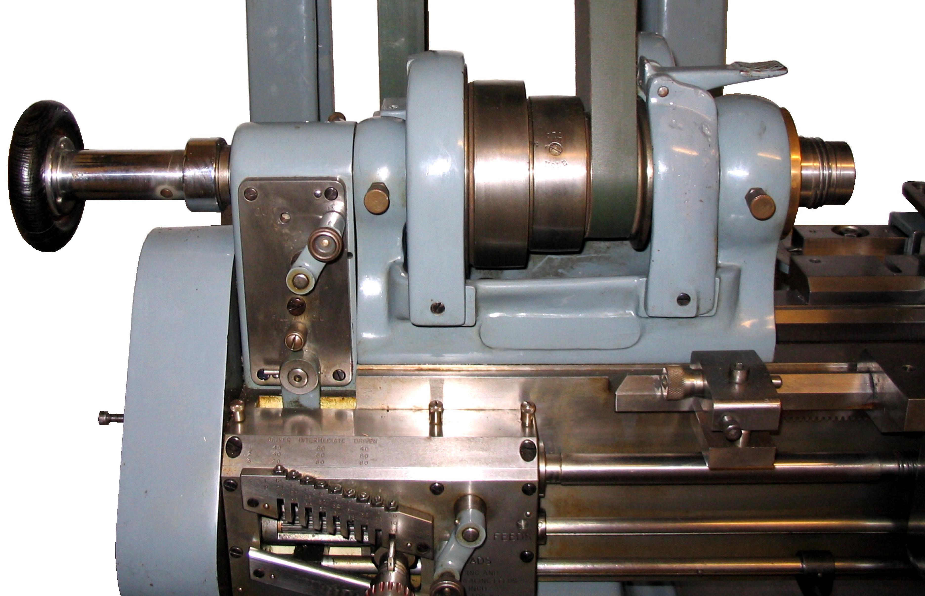
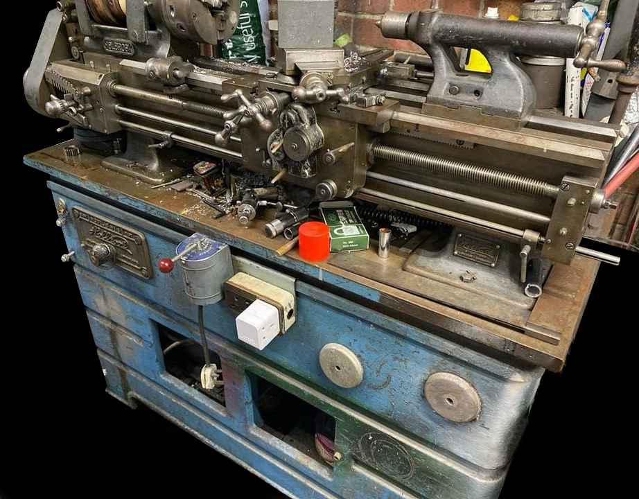
Fitted with nickel-chrome gears, the quick-change screwcutting gearbox provided a useful range of twenty-seven threads and feeds - its drive from the headstock passing first through an oil-immersed gearbox that could engage or disengage the feed at the flick of a lever. Beneath the gearbox was a second lever to engage reverse and forward motions for feeds and screwcutting; the large spur-type reversing gears, built into the bottom of the gearbox, ran in an oil bath and could be operated whilst the lathe was running--but only (like lather Holbrook lathes) at spindle speeds of up to 125 r.p.m., the normal limit for screwcutting. Conversion gears were provided to cut metric, BA and metric pitches and the leadscrew, which could be engaged and disengaged by a sliding gear where it passed into the gearbox, was used only for screwcutting, a separate shaft, carrying automatic knock-off stops, being used to transmit power to the doubled-walled apron. The leadscrews were corrected against a master thread, itself certified by the National Physical Laboratory as accurate to within plus or minus 0.0001 over any one foot length, at 68 F.
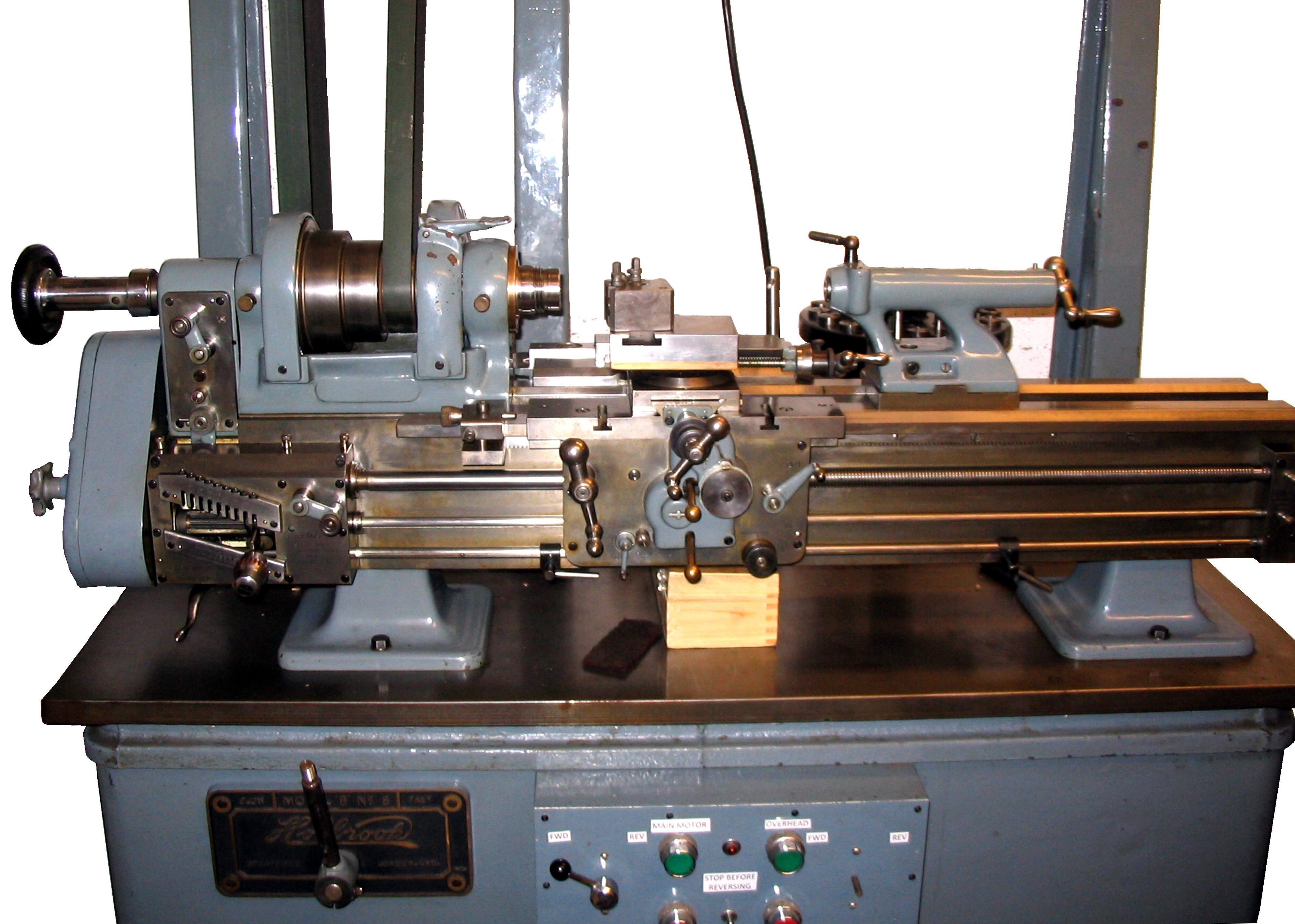
Doubled walled, the heavily constructed apron had all its shafts fully supported on double bushes. The phosphor-bronze split clasp nut for screwcutting was also closely supported between the walls, instead of being overhung from the inner wall as was (as still is) common practice. The power sliding and surfacing feeds were engaged by friction cones, each with its own control and the threads and feeds selector was also apron mounted. The trip for the automatic apron-feed was provided with a micrometer adjustment marked in one-thousandths of an inch; rotating the dial gave an axial movement to a long sleeve that covered the stop rod and projected from each side of the apron with sliding clamps on the stop rod allowing a coarse setting of the disengage point to be made first. The automatic knock-off facility worked superbly, and with perfect, repeat accuracy. A dial thread indicator was neatly built into the apron and protruded through its front face.
Fitted with rather small zeroing micrometer dials, the compound slide rest had a top slide that could be swivelled through 360 degrees and reflected precision plain-turning practice by having an unusually long travel; T-slots, intended to mount boring jobs or special toolholders, were formed in each of the apron wings.
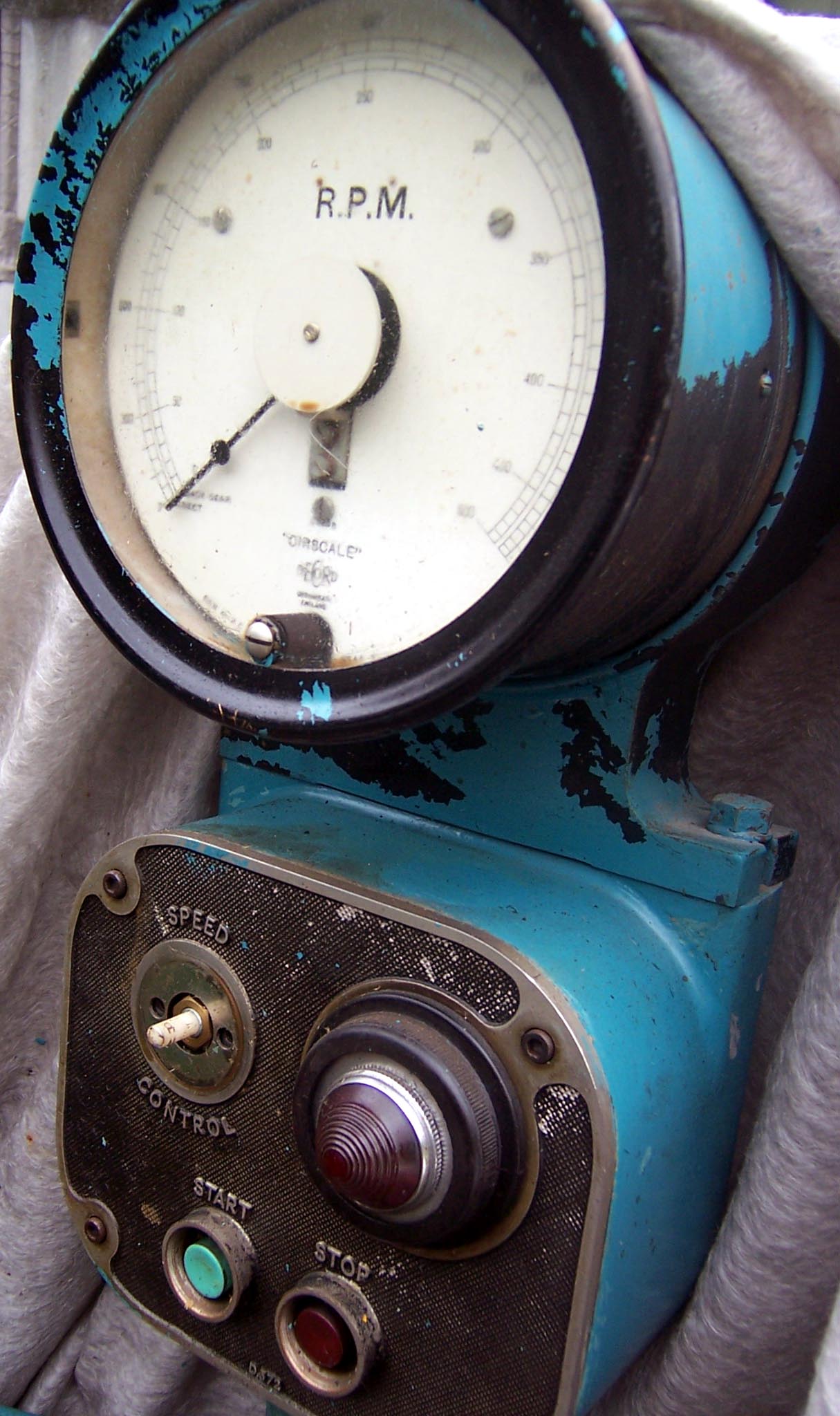
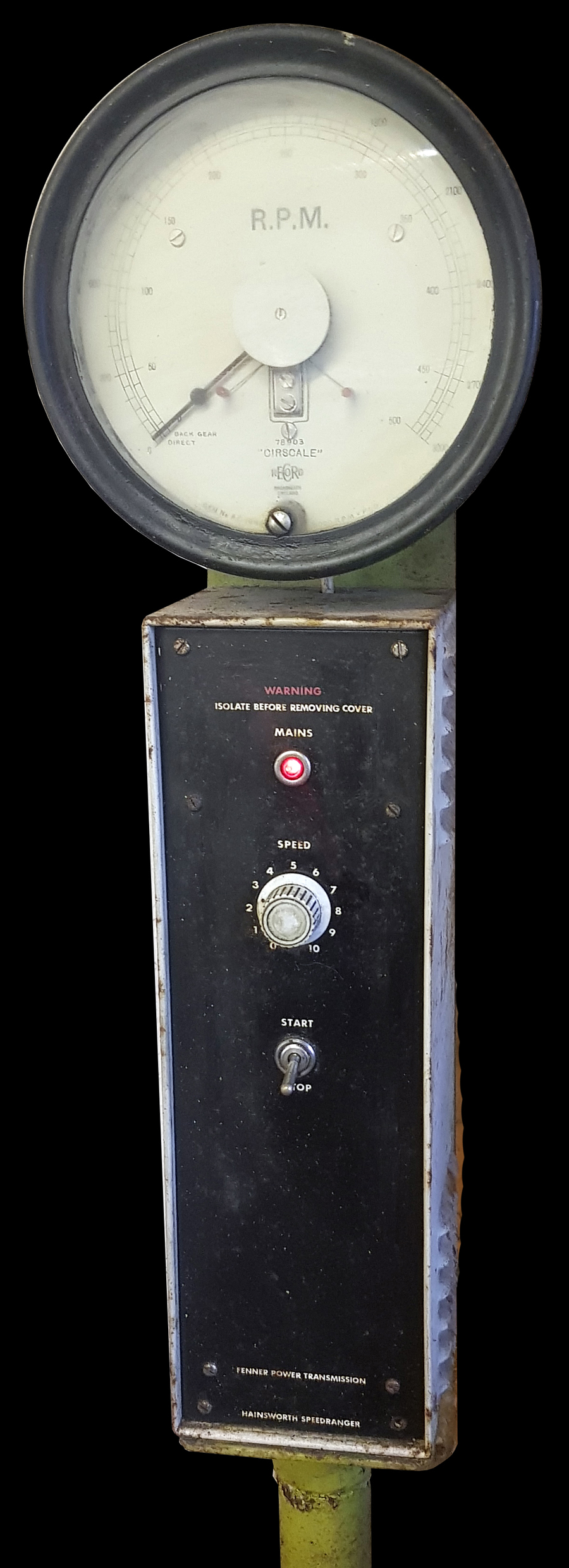
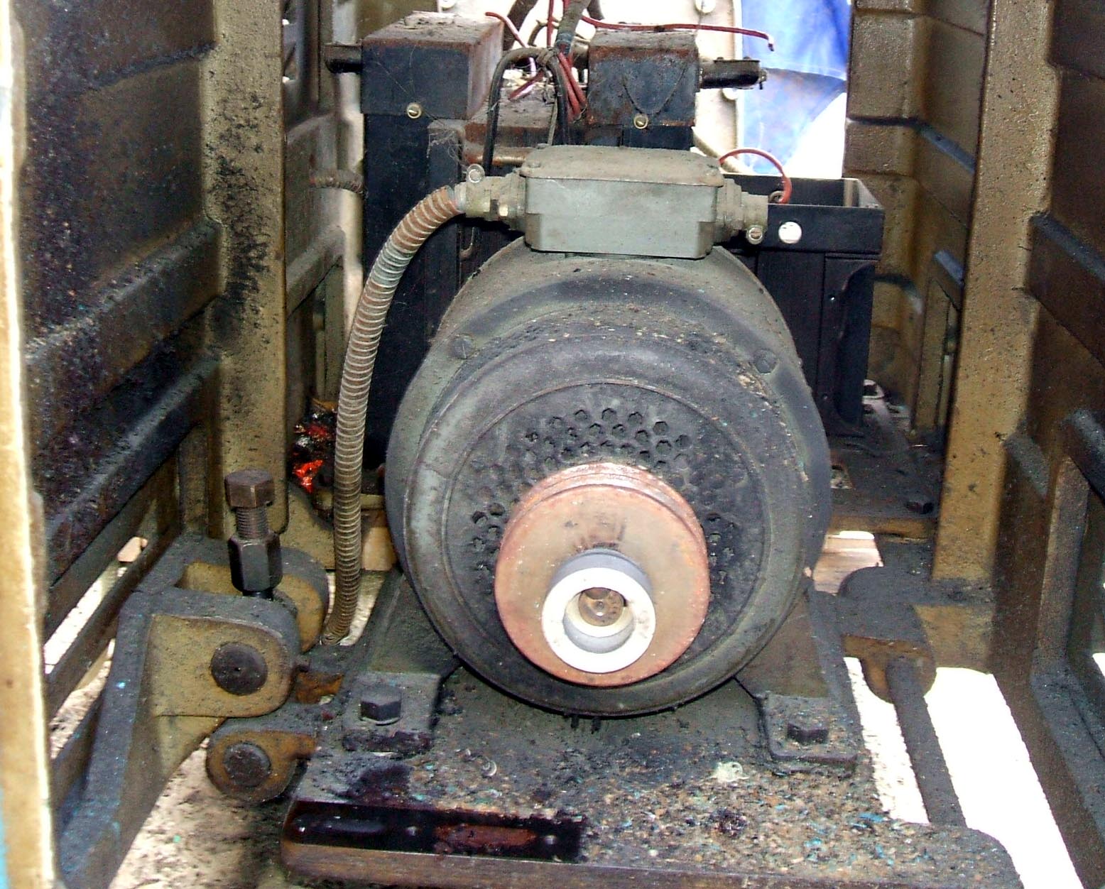
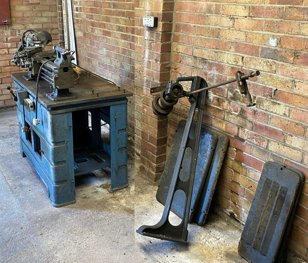
Supplied with early lathes was an all-belt drive system with either a fast-and-loose, two-speed, ball-bearing, wall-mounted countershaft unit with a foot-operated belt shifter - or much the same assembly held on wooden board supported by cast-iron uprights bolted to the back of the stand. However, to improve the drive system, in the early 1940s a version of the lathe was listed as the Type C8 Electronic, this having an enclosed, backgeared headstock and variable-speed drive - with the rotary speed dial, push-button starter and rev counter mounted in a housing carried on a post fastened to stand towards its tailstock end. The variable-speed drive - of some complexity and great cost - used a massive B.T.H. 2 h.p. 250v DC motor that drove, using twin V-belts, direct to the spindle pulley. Control was by an early electronic drive system that used a thyratron system, again by BTH, originally held in a large sheet-steel cabinet bolted to the headstock end of the lathe's cast-iron cabinet stand. In some respects the drive would have been similar to that developed by "Ward-Leonard" (used on some Cromwell lathes) and that fitted to the American Monarch 10EE. The result was a step-less speed range, with dynamic braking, from 20 to a remarkable 5000 r.p.m. The C8 is known to have run with uncanny smoothness, a coin balanced on its edge on the headstock of a new lathe being perfectly stable even at maximum r.p.m.
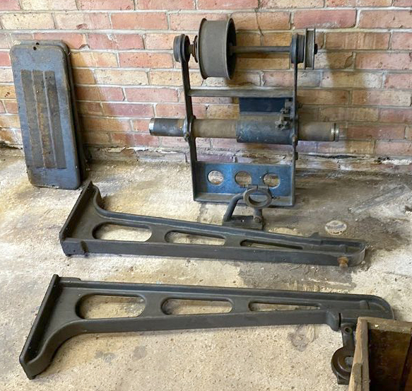
4' 6 " long (1320 mm) and 1' 5" (432 mm) wide, the early lathes weighed approximately 440 lbs. and were supplied, as standard, with an 8" diameter T-slotted faceplate; fixed and travelling steadies and a hand Tee rest. Although no chucks were included with the ordinary equipment, nine collets from 1/8" to 5/8" were - and are often found held in a neat rotating circular holder (made from oak) together with the draw bar and the necessary headstock spindle-adapter sleeve. As the C8 was so expensive, it is believed that only around ninety examples were built, a number of which are known to survive..
|
|