 |
|
|
|
|
|
|
|
|
|
|
|
|
|
|
|
|
|
|
|
|
|
|
|
|
|
|
|
|
|
|
|
|
|
|
|
|
|
|
|
|
|
|
|
|
|
|
|
|
email: tony@lathes.co.uk
Home Machine Tool Archive Machine-tools Sale & Wanted
Machine Tool Manuals Catalogues Belts Books Accessories
EXE Lathes
Main EXE Page Continued Here
EXE Photographic Essay
EXE 2.5" Lathe EXE Miniature Surface Grinder
EXE Exlet Lathe A Fine & Original EXE
With thanks to the enthusiastic Jim Cockburn of Chichester who
provided much of the chronology for this page.
|
|
|
|
|
|
|
|
|
|
|
|
|
|
|
|
|
|
|
|
|
|
|
|
|
|
|
|
|
|
|
|
|
|
|
|
|
|
|
|
|
|
|
|
|
|
|
|
|
|
|
|
|
|
|
|
 |
|
|
|
|
|
|
Super EX 33/8" and 31/2" lathe with 55° edges to the bed as manufactured during the late 1930s
|
|
|
|
|
|
|
|
|
Established in 1921, the Exeter Tools & Machinery Ltd. of Aplington Road, Exeter, was well known for not only for high-class model-engineering lathes (1923 until 1939) but also various light drills, a steel-bodied independent 4-jaw chuck with the mounting thread inside the body, the "Nulock" toolholder and the once-famous and highly-useful Keat's Patent Combination Angle Plate and, in later years, a glass lathe. In 1925 a separate branch of the Company, Exe Engineering, was formed to manufacture the lathes whilst the original concern continued to deal with tools and engineering accessories. Exe existed until 2015 and made until the end (and under the same name), a long-established, small, but high-precision toolroom-class surface grinder and engaged in machine-tool reconditioning and general engineering.
Their first lathe, introduced to the public at the 1923 Model Engineering Exhibition in London, was the simple yet ingeniously-designed 21/2" centre height round-bed screwcutting EXE. The lathe stayed in continuous production until 1939 and was available in both short and long-bed versions; further details are shown here.
Next to market was a basic, 2-inch centre height, no-frills, plain-turning machine the "Exlet". This lathe had a flat-topped bed, a carriage propelled along it by a hand-operated leadscrew and a headstock drive system similar to that used on the company's other lathes (a very large diameter overhung pulley that both took the place of backgear in providing slow speeds and also added something of a flywheel effect to the drive). The slide-rest assembly was of the simplest possible kind with a single, swivelling tool rest pivoting on the saddle. Both a bench and stand-mounted model were offered, the latter being a light-weight version of that used on the 21/2" lathe. For the use on the owner's own bench, EXE offered a special lightweight "foot motor" that an owner could use to rig up an independent drive system. In 1927 the Exlet cost £3 : 17s : 6d, a price that makes an interesting comparison with the £4 : 10 : 0d asked for the conventional backgeared, screwcutting and gap-bed (but very lightly built) 3" Randa lathe and around £9 : 0s : 0d for a 4" Round-bed Drummond. However, despite the competitive price, by 1935 the model had disappeared from the maker's lists and, judging by its extreme rarity today, few can have been sold. If you have an Exlet the writer would be very interested to hear from you.
Continued below:
|
|
|
|
|
|
|
|
 |
|
|
|
|
|
|
The simple and now very rare Exlet lathe from EXE
|
|
|
|
|
|
|
|
|
|
|
|
4-inch Super EXE
In September 1927, again at the National Model Engineering Exhibition in London, Exeter Engineering announced their first conventional lathe - though that description should really be in parenthesis if the number of novel features included in the design is taken into consideration. Known as the "Super EX" lathe it had a centre height of 4.125 inches, a between-centres' capacity of 19 inches and represented a brave effort to overcome some of the limitations of small-lathe design. The basis of the machine was a rigid, flat-topped, square-edged, cantilever-style bed 415/16"-wide with a very deep section above the extra-long foot; it was cast in iron as an open, inverted box without core holes in the top (into which chips could accumulate) and with the only opening positioned underneath the foot. The bed had a gap section that allowed material up to 12 inches in diameter and 21/2" thick to be turned. an enclosed headstock spindle, a simple, very short non-T-slotted cross slide and a boxed-in dog clutch on the 3/4-inch diameter, 8 t.p.i. square-thread leadscrew and a set-over, No. 2 Morse tailstock (with, sadly, a cheap direct-acting screw to lock the barrel). The gap in the bed was right on the limit of what was possible: with the carriage brought right up to the edge and the cross slide advanced as far forwards as possible, the tool could just reach the spindle nose. Later models were given a detachable gap piece, a most unusual refinement on so small a lathe
As on all EXE lathes, although there was no backgear to allow really low speeds, the immensely large, 4-step, overhung headstock-drive pulley in cast iron (which weighed 12 lbs and contributed a powerful flywheel effect) largely compensated for this; although mounted outboard, the pulley was heavily dished to limit the potentially damaging leverage forces it could transmit to the left-hand bearing; a ring of 180 holes were provided for use in division work, a number later reduced to 60 on the smaller pulley fitted to the later and similar 3,25", 3.375"" and 3.5" centre-height versions. Unfortunately, although having many factors, neither set of holes, 180 or 60, allowed the operator to deal with octagonal components, or set plus or minus 45° angles from a zero datum - or deal with popular 100-division tasks. However, the location holes, being much deeper than usual and combined with a strong steel indexing arm and pin, allowed a really solid, rock-free setting to be achieved.
Until 1935 EXE lathes were intended to be driven by round "gut" leather bands, a distinct disadvantage when heavier cuts were needed; Drummond, for example, had abandoned the round belt in 1921 and changed to an inch-wide flat, an option denied to Exeter Engineering by the compact nature of their drive system. The 1935 change finally allowed the use of conventional V-belts - though the option had been available since 1931 when this type of drive had been introduced on a wide variety of American-built wood and metal-working machinery. In reality, a Z-section (10 mm wide) V-belt works perfectly well on the earlier lathes as well - as it will on the majority of other "gut-drive" machines from other manufacturers.
Early headstock spindles ran in "plain cone and ball thrust bearings" and had a bore of 17/64" with a non-standard taper that, while the same angle as a No. 1 Morse was of larger size, yet smaller than a No. 2. Later spindles were bored through to take a 0.75" diameter bar and used a No. 2 Morse taper - a rather more sensible arrangement, but one upon which advertising and other literature is silent. Fitted to the enclosed spindle was a unique "screw-cutting dog clutch" that, the makers claimed, allowed "even those without previous experience (to) cut any thread easily and quickly" - if only the generation of good-quality threads were so simple. However, in the sense that it was impossible to "pick up" a thread at the wrong point and spoil a job, the device did work efficiently - and was well received in articles at the time by experts (in addition, the headstock was considered well enough engineered to be adopted as the basis for an ingenious multi-function machine tool the "Metalmaster" - the details of which make fascinating reading).
For drive by hand, the leadscrew (which ran through a long "full-nut" of bronze or cast-iron bolted to the underside of the saddle front) was fitted with a usefully large though ungraduated handwheel at the tailstock end and a dog-clutch, operated by a steel lever formed as one piece with a ball on its end, at the other. At first neatly (and expensively) enclosed, the dog clutch provided an instant release when machining under power - and many owners made up simple automatic knock-off devices to allow exact turning up to a shoulder. However, a second reason behind its fitting was a practical difficulty unmentioned by the makers: as owners quickly discovered when screwcutting with the help of the headstock clutch it was necessary (once a cut had finished) for the carriage to be wound back manually using the wheel at the tailstock-end of the leadscrew while the changewheels remained in mesh. If the thread being cut was fine the gears would simply not "reverse" back against the high-ratio gearing being employed. Although early lathes had flat, paddle-shaped steel handles on the dog-clutch controls of both leadscrew and headstock spindle, later machines were fitted with handles terminating in one of the first forms of proper plastic, a strange pink-coloured, self-crumbling substance.
On early versions of the lathe, until 1927, just a single swivelling tool slide was fitted, after that a very short plain cross-slide was used, topped by a proper swivelling top slide locked by just a single, square-headed bolt. The toolpost was a miniature version of the crude-looking but versatile 4-bolt, double-clamp toolpost then common on much larger English lathes. Feed screws were ordinary right-hand pitch, Whitworth-form that gave a "cack-handed" feel i.e. turning the feed handle to the right caused the slide to retract rather than advance - a situation easy enough to adapt to but dangerous if moving from a conventional machine, or using a mixture of the two in one workshop. For the first two years of production no graduated micrometer dials were fitted but when introduced (simultaneously with that on the 33/8" lathe), was in the form of a simple but effective large-diameter wheel engraved on its flat rim - but fitted at first to only the cross-feed screw.
Continued below:
|
|
|
|
|
|
|
|
 |
|
|
|
|
|
|
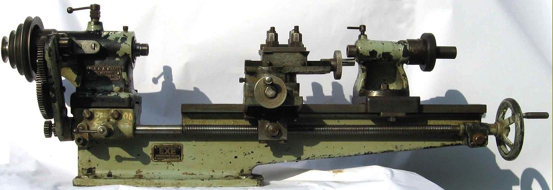
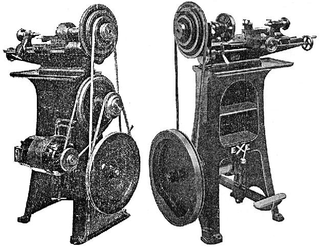
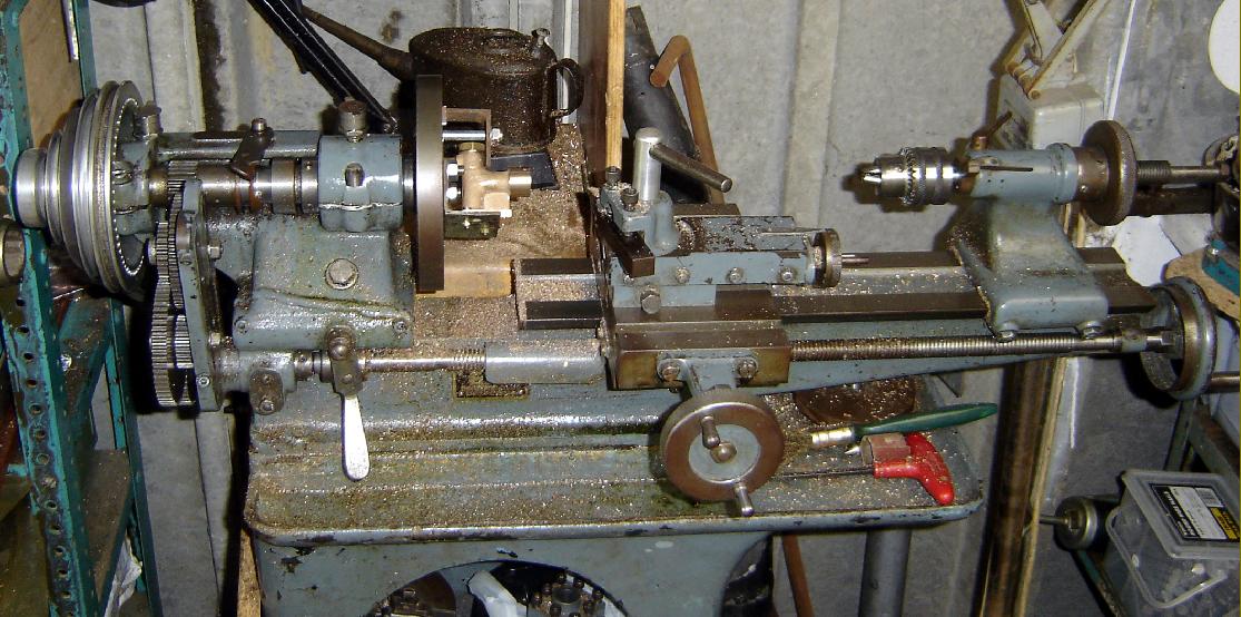
A rare and early 4-inch EXE with a right-angle edge to its 415/16"-wide bed, an enclosed headstock spindle, a simple, non-T-slotted cross slide (with no micrometer graduations on the handwheel) a basic 4-bolt toolpost, an enclosed dog clutch on the leadscrew and a set-over, No. 2 Morse tailstock. The actual centre height was 41/8", the distance between centres 19" and the spindle nose 1-inch BSW with a No. 2 Morse taper. Note the gap in the bed, on the very limit of what was possible with the carriage brought right up to its edge; this on-the-limit design was eventually to be replaced by a detachable gap section, an unusual refinement for such a small lathe. The overhung, 4-step headstock pulley is not original - the usual, very large one having being removed and the drive system altered by a previous owner. It's worth noting that these lathes were exceptionally well built; all the slideways were hand scraped to a perfect fit and moved with an unusual smoothness; the headstock spindle was finished to a high degree of accuracy and users report that this situation is retained over many years of hard use.
|
|
|
|
|
|
|
|
 |
|
|
|
|
|
Continued:
Usefully identical in tooth form to those on Boxford and South Bend 9-inch lathes (but fitted to comparatively small-diameter studs) the 18 DP screwcutting changewheels were arranged in a rather clever way: the headstock spindle, being driven from its left-hand end, was clear in the middle and advantage was taken of this to mount on it a simple but ingeniously contrived dog clutch to the first part of the changewheel drive; this device allowed threads, even ones of an odd-number, to be engaged and disengaged without error. The 24-tooth gear fitted to the left-hand end of the headstock spindle dog clutch drove what appeared to be an ordinary set of changewheels - however, the number of gear teeth on each wheel were all multiples of 3 instead of the usual 5 and that, combined with an 8 t.p.i leadscrew, meant that the multiples (of three) could be converted in a far greater range of vulgar fractions, and thread calculations made rather more easily.
Besides the ingenious mechanical refinements, the lathe was very well finished with all the slideways, including the bed, having a ground rather than the milled finish common on other small lathes at the time.
Over the years various kinds of both bench and stand-mounted countershafts were available: one model of bench countershaft featured a four-step final-drive pulley with a "fast-and-loose" drive from the motor (which gave the effect of a clutch) whist the other dispensed with this arrangement and was driven directly from the motor by what the makers described as a "special joined V-belt". The original cast-iron stand provided for the 4-inch lathe was similar to that already offered for the 2 and 2.5" "round-bed" lathes, but of greater weight and rigidity with solid webs and a right-footed treadle; in 1929 a wider cast-iron stand of conventional appearance with two legs and a centrally-positioned treadle was introduced that allowed either foot to be used and muscles built up equally in both legs.
The 4-inch was advertised until 1935, when it disappeared from the lists to be replaced as the company's top-of-the-range model by the 3.5-inch "Super EXE".
Continued below:
|
|
|
|
|
|
|
|
|
|
|
|
|
|
 |
|
|
|
|
|
|
The heavy cast-iron stand introduced in 1935 for all versions of the cantilever-bed lathe.
|
|
|
|
|
|
|
|
|
|
|
|
Continued:
31/4", 33/8" and 31/2" Super EXE
In 1928, once more at the National Model Engineering Exhibition (and with the successful 2, 2.5" and 4-inch lathes in production), the company took the strange step of introducing a 31/4" lathe with an actual centre height of 33/8". If this had been a lathe of greater capacity than the existing range, of some radically different design, very much cheaper to produce or able to be issued in a variety of money-saving specifications, one could have understood the reasons behind it, but here was a machine so similar to the 4-inch that it would compete in the same market segment - yet required the making of new patterns and jigs to manufacture.
Not dissimilar to that used on the 4-inch model, the cantilever-form bed had 55° instead of 90° sides - and this was yet another Exeter Engineering departure from standard, for most small lathes at the time had their bed edges set at 60°. The gap in the bed was now a detachable section, allowing the owner some increased versatility with larger jobs, yet allowing the carriage to run, fully supported, right up to the spindle nose. The slide arrangement mirrored that of the 21/2" lathe with a single tool-slide that socketed into and swivelled about the front of the saddle. The top surface of the slide was provided with 11 tapped holes designed, in conjunction with two traverse T-slots that crossed the saddle, to allow the owner some creativity and choice in setting up boring and milling and other tricky, non-turning operations.
Followed established EXE tradition the headstock spindle was driven by a large, overhung 4-groove iron pulley (rather smaller than that on the 4-inch) with 3 steps for normal speeds and a single extra-large one to give a slow speed in imitation of proper gear-driven backgears. It also carried the usual EXE dog clutch and a 7/8" diameter, No. 1 Morse taper spindle that was bored through 3/8" (a figure of 1/2" was also quoted by the makers) and ran in parallel bronze bushes that were split on one side and closed down by compression screws against a fibre insert. The spindle nose was threaded 1/2" x 16 t.p.i Whitworth, the leadscrew 1/2" x 8 t.p.i Acme and the changewheels, in steel, of 16 DP running on rather small-diameter 7/16" pins.
A cast-iron stand was available, fitted with right-foot-only treadle, that appears to have been identical to the one offered for the 21/2" lathe; unfortunately, when sold in a stand-mounted form, the price of the lathe rose from £10 : 12s : 6d to £16 : 15s : 0d - a substantial increase of 58%.
In 1929 some improvements were announced to what was now called the '33/8" Super EXE': the mandrel bore was increased to 1/2" (but 17/32" in reality, so allowing a 1/2" bar to pass clear through), the saddle carried a conventional compound slide rest with a T-slotted cross slide and swivelling top slide and, happily, the 10 t.p.i. Acme-form cross feed screw had the outer flat rim of its handwheel engraved with a micrometer scale - an improvement mirrored simultaneously on the 4-inch lathe. The Super EXE stayed unchanged until 1935 when the centre height was increased to 31/2" by the use of deeper headstock and tailstock castings; this allowed the detachable gap to accommodate work a full 9" in diameter by 2.125" clear of the faceplate. The spindle bore was increased to 3/4", an unusually large size for a small lathe, and mention was also made of the increase in bearing size to accommodate what must have been a substantially larger diameter spindle; the size of the taper in the nose remains a mystery, however - but scaling up the original dimensions indicates that even a No. 3 Morse would have been possible. The stand was also significantly improved, now being in the form of a heavy cast-iron box with a pair of tool shelves and able to mount either a central pedal or a rather complex and over-engineered 16-speed motor-drive system with, in effect, three cast-iron flywheels (fitted with proper A-section V-belt grooves) to smooth out the drive. The 0.5 hp motor was mounted on vertical rails at the back of the headstock-end leg and could be moved up and down to adjust the belt tension - the setting being locked by a convenient Tommy-bar-ended screw at its base. The motor drove first to a heavy pulley that ran on a fixed stud with a ball-bearing race and from there to a massive flywheel, again running on ball bearings but mounted on an eccentric stud that could be released and the turned to slacken the belt. When running on top speed the combined mass of the three cast-iron pulleys would certainly have stored a vast amount of energy (like the Portass lathe featured here) and allowed the lathe to bite into heavier turning jobs - although waiting for it all to come to full stop must have been frustrating for the operator.
Screwcutting was by changewheels, a full set comprising 14 viz. 2 off 18t, 21t, 24t, 27t, 30t, 33t, 35t, 36t, 38t, 39t, 54t, 60t and 72t.
In the mid-1930s the basic lathe was listed at £26 : 10s : 0d with the treadle-stand adding a further £10 and electric drive, complete with motor and starter, doubling the price to £52 : 10s : 0d. (this compares to the £26 : 10s : 0d charged throughout most of the 1930s for a Drummond M Type complete on a treadle stand). The bench-mounted EXE countershafts were priced at £4 : 2s : 6d for the fast-and-loose version, and £3 : 12s : 0d for the large, single-pulley type. To give some idea of how expensive the lathe was, inn the mid-1930s (for a short time) it was possible to buy a new car for £100, either a Ford 8 or a 2-seater Austin 7.
|
|
|
|
|
|
 |
|
|
|
|
|
|
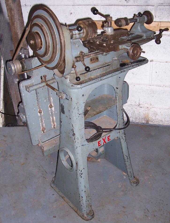
EXE mounted on a post-1934 treadle stand modified to carry a substantial home-made countershaft
|
|
|
|
|
|
|
|
 |
|
|
|
|
|
|
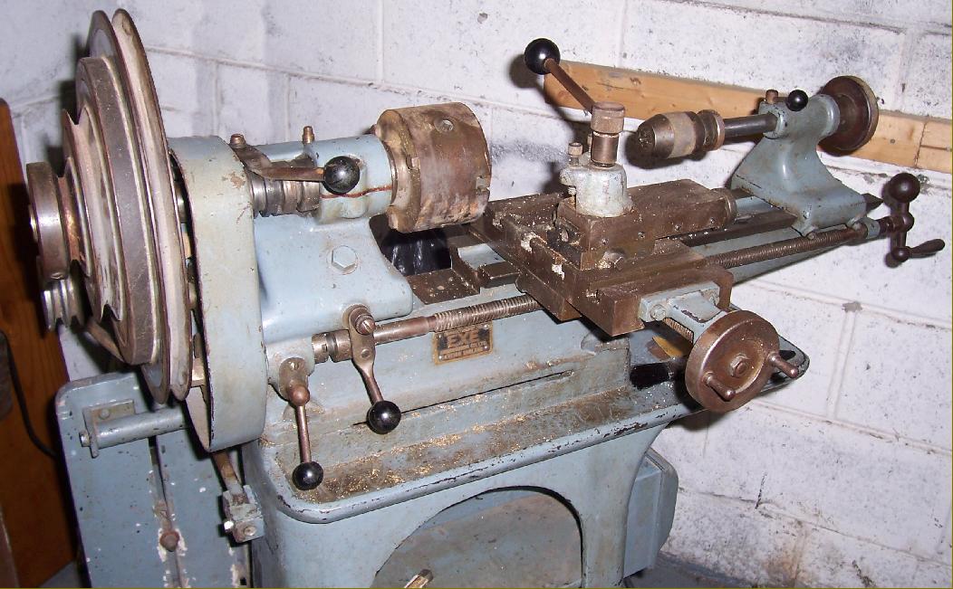
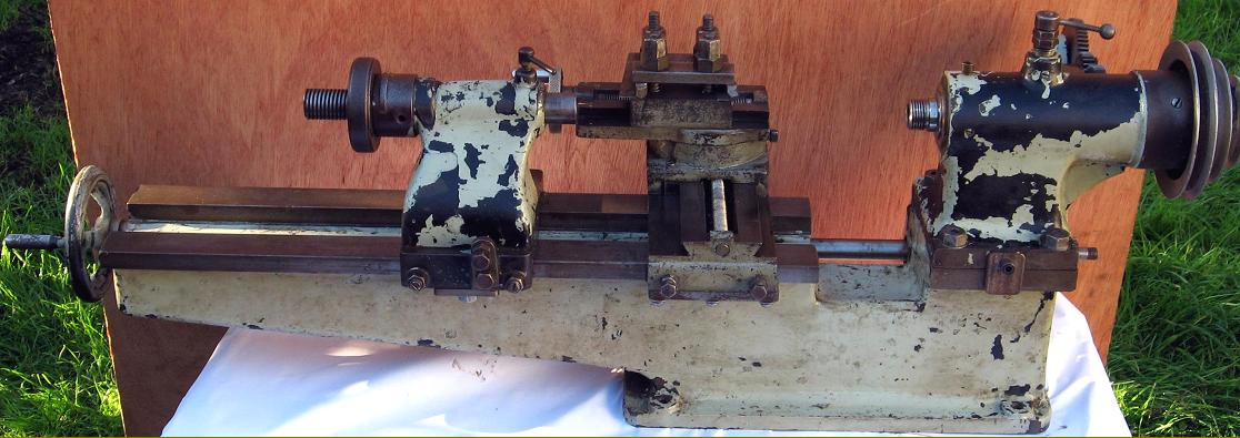
The very heavy build of the EXE V-edged cantilever-bed lathe is evident from this picture. Note the step-out bracket on the front of the cross slide to give additional travel (a useful facility when using the cross slide as a boring table or when mounting a milling slide) and the detachable gap section in the bed. This example has the simple, non-set-over tailstock with a locking screw at the back fitted with a bronze pad to protect the bed and, at the front, two screws that more against precision, hand-scraped scraped steel pads.
|
|
|
|
|
|
|
|
 |
|
|
|
|
|
|
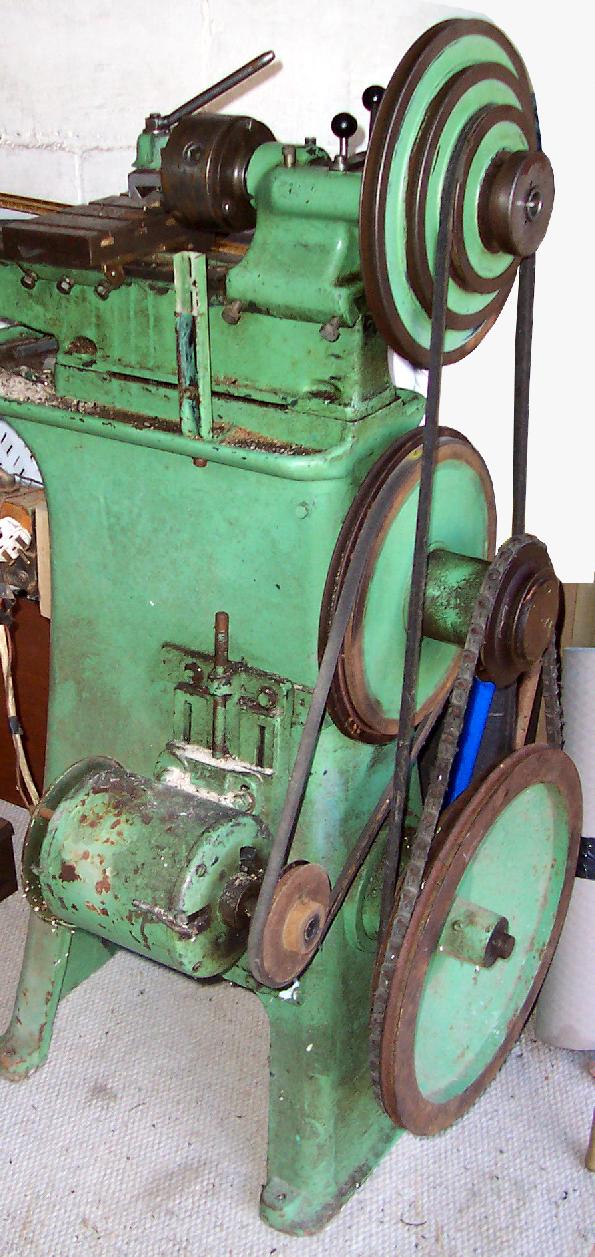
The full motorised version of the EXE with its heavy and complex maker's drive system
|
|
|
|
|
|
|
|
 |
|
|
|
|
|
|
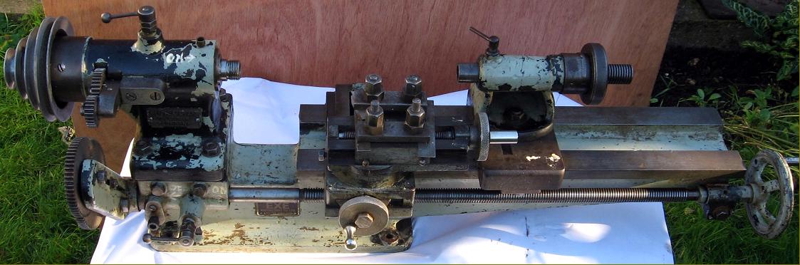
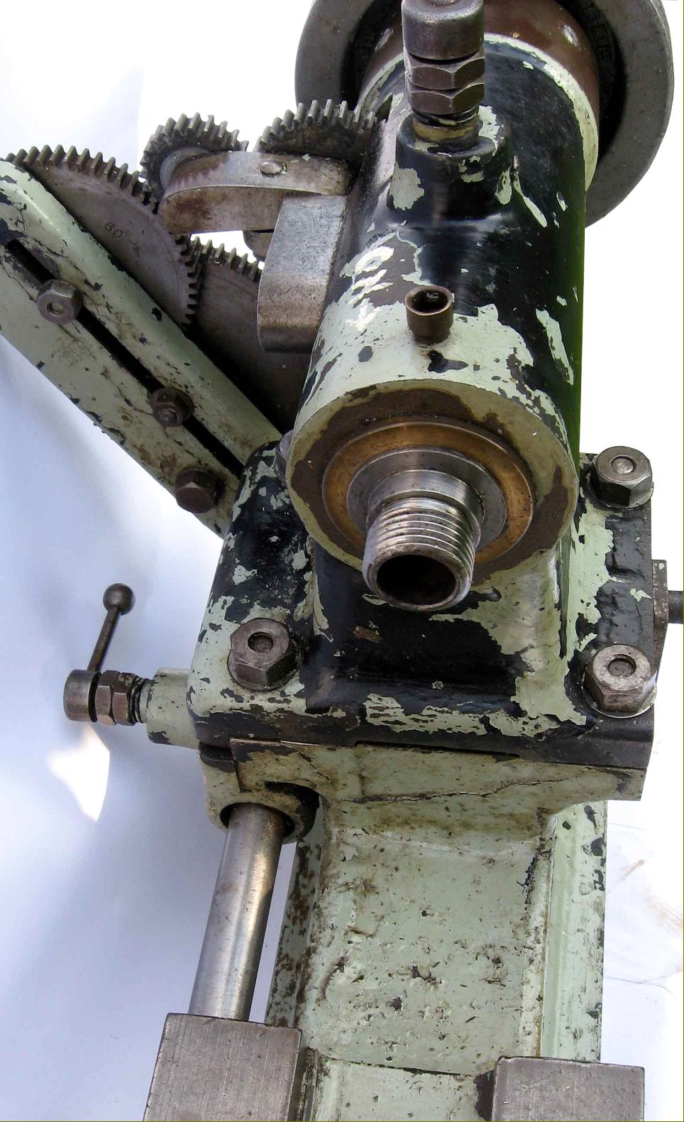
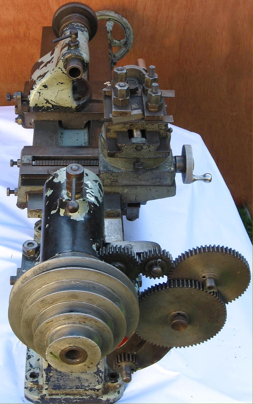
Another EXE with the large spindle pulley removed and the drive system adapted to a more convention type of countershaft
|
|
|
|
|
|
|
|
 |
|
|
|
|
|
|
Above and below: the early 4-inch EXE with right-angle edged bed and with both headstock spindle and leadscrew dog clutch enclosed
|
|
|
|
|
|
|
|
 |
|
|
|
|
|
 |
|
|
|
|
|
|
|
|
|
|
|
Main EXE Page Continued Here
EXE Photographic Essay
EXE 2.5" Lathe EXE Miniature Surface Grinder
EXE Exlet Lathe A Fine & Original EXE
EXE Lathes
email: tony@lathes.co.uk
Home Machine Tool Archive Machine-tools Sale & Wanted
Machine Tool Manuals Catalogues Belts Books Accessories
.
|
|