Home Machine Tool Archive Machine-tools Sale & Wanted
EXE 2.5" Lathe Continued Here
EXE Exlet Lathe A Fine & Original EXE
|
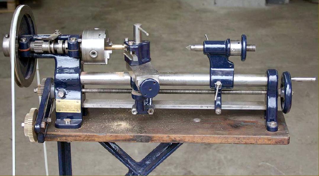
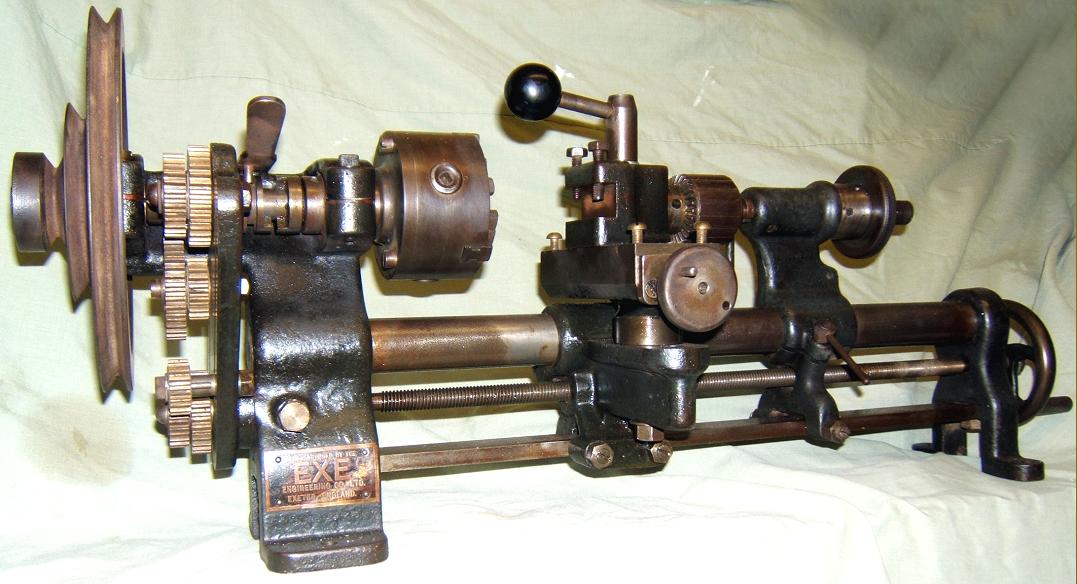
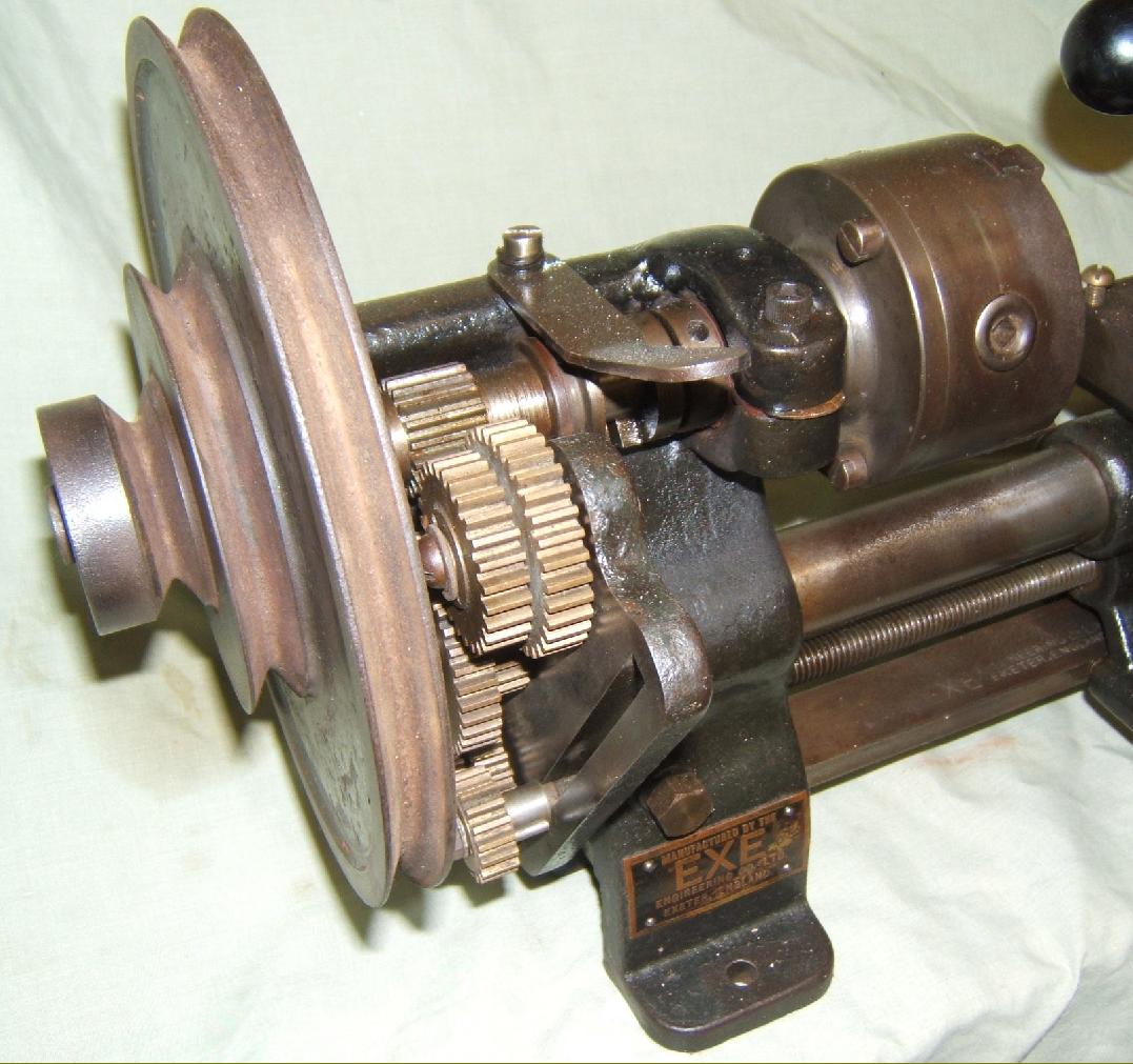
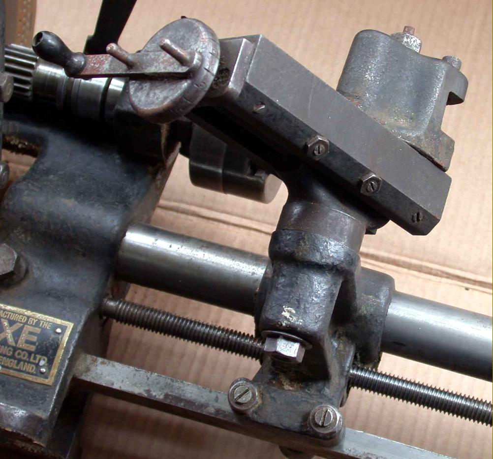
With only an archdeacon and a professional engineer as owners, the early, black-painted EXE 2.5" shown below has survived in excellent, original condition. The dividing plate fitted to the front face of the headstock pulley is not original (as standard a single ring of 60 holes was provided) - but, astonishingly, the bronze set screws let into the tailstock casting that bear against the bed to align the unit are. |
|
|
|
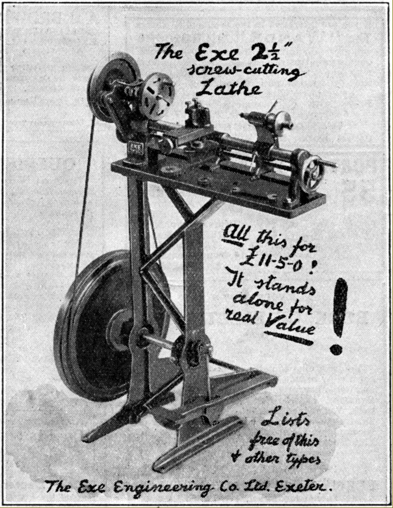
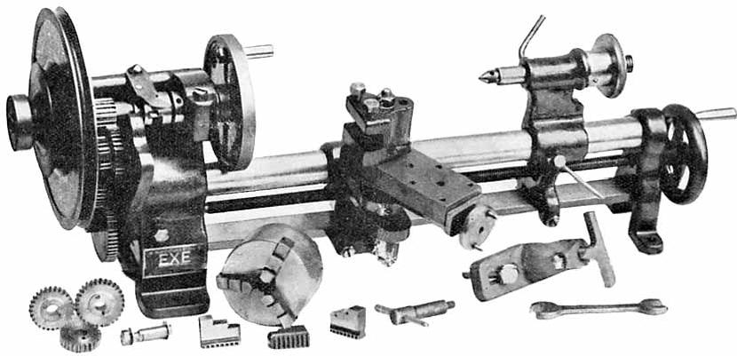
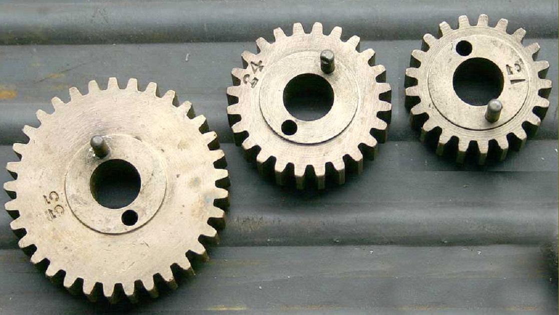
The 2.5" EXE lathe shown here in its 1926 form. Besides a 3-jaw chuck, faceplate, centres and changewheels a wood-turning test was also included as part of the standard equipment. |
||
|
A 1/4 scale model 2.5" EXE lathe just 6" long and built by the makers from parts machined on the prototype of its full-sized brother. |
|
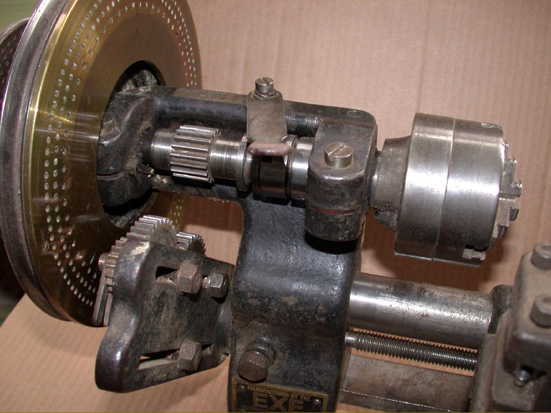
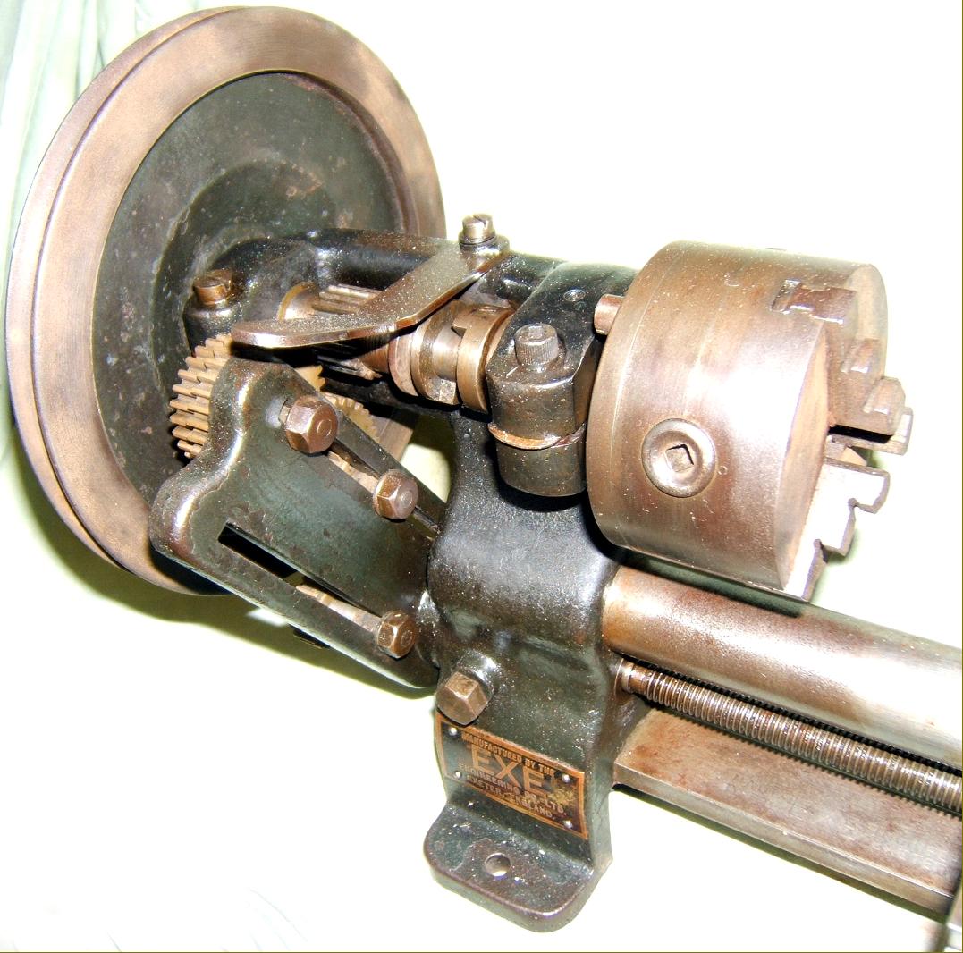
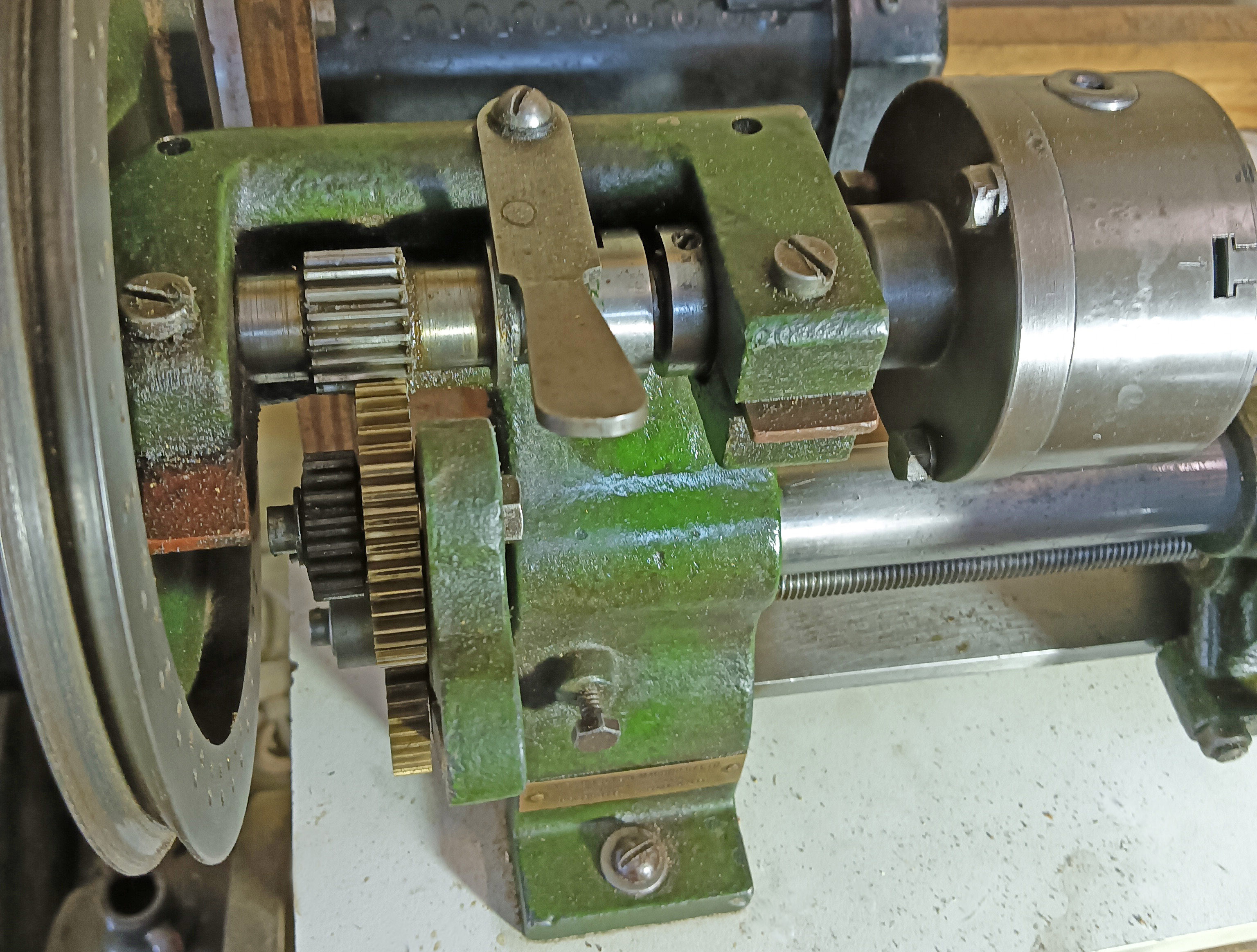
The headstock design, with adjustable bronze bearings was of unusual construction being "open" at the front with the back wall of the headstock rising up level with the top of the bearings. Fitted to the exposed spindle was a unique "screw-cutting dog clutch" that, the makers claimed, allowed "even those without previous experience (to) cut any thread easily and quickly" - if only the generation of good-quality threads were so simple. However, in the sense that it was impossible to "pick up" a thread at the wrong point and spoil a job, the device did work efficiently - and was well received in articles written at the time by experts. |
||
|
|
|
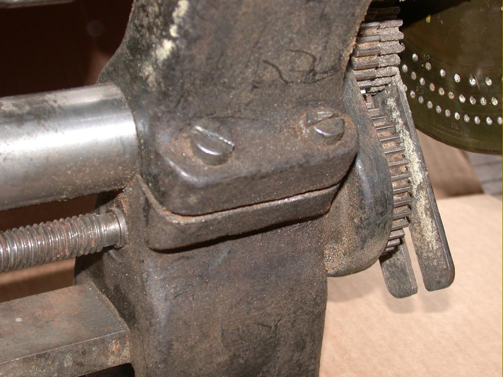
The rear wall of the headstock casting was built up level to top of the spindle bearings. The headstock and left-hand foot were cast as one, precision bored and slit along the rear side with two screws to close the casting up and tighten it to the lathe bed. |
||
|
|
||
|
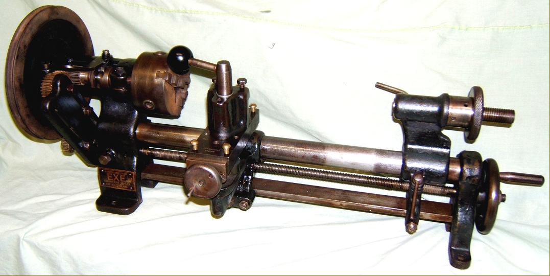
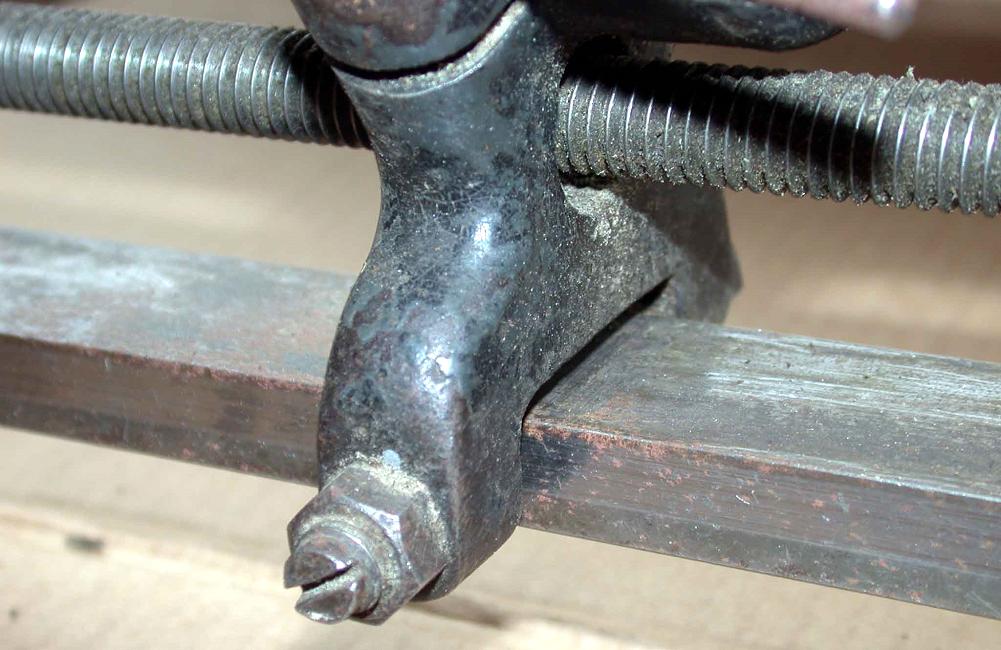
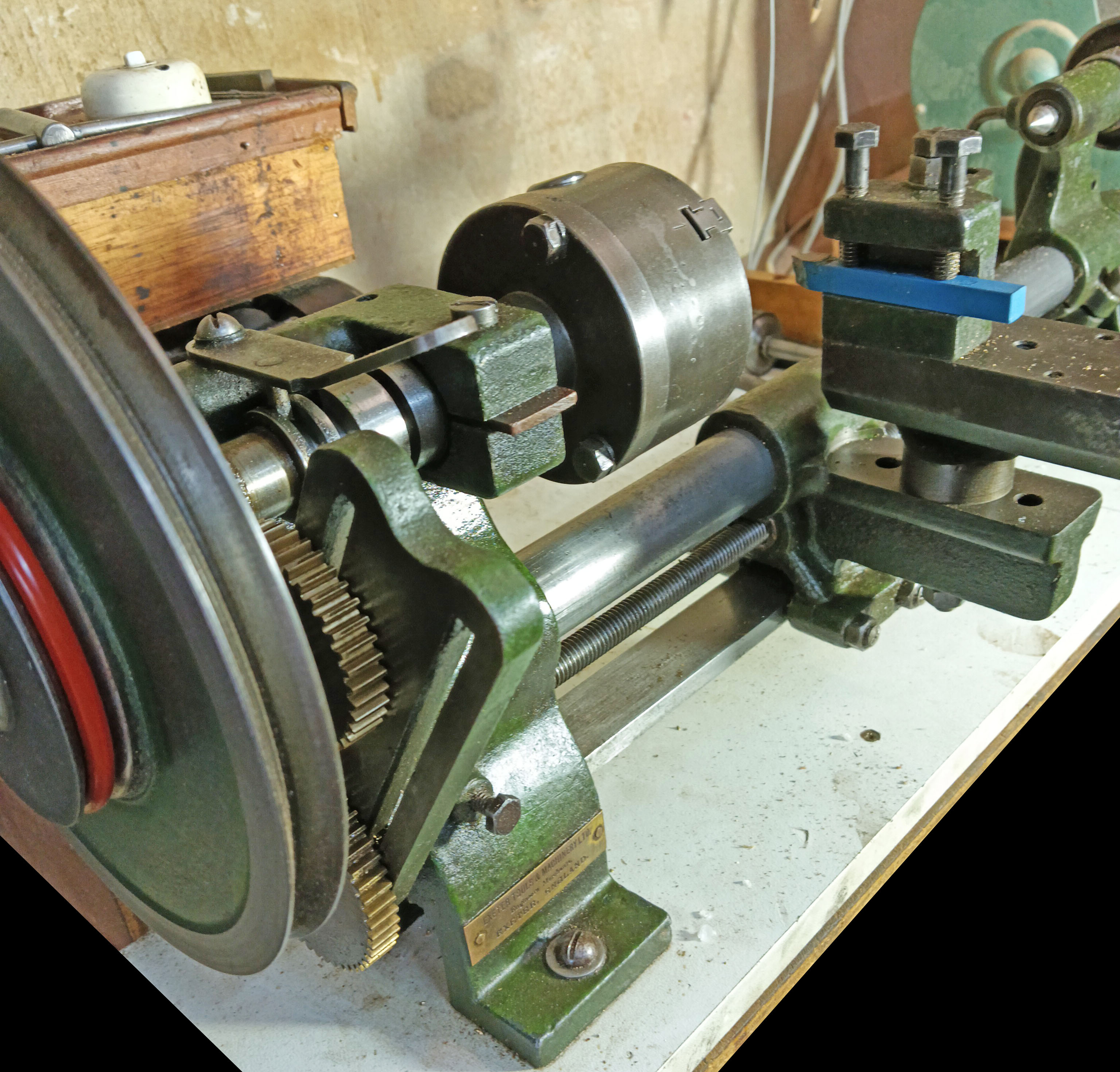
EXE fitted a separate flat bar, placed horizontally below the round bar, to provide a "lever point" against which the twisting forces from the tool could be absorbed - and also to reduce the effects of wear on the main bed. In order to align the carriage and tailstock they were fitted with an adjustable gib strip at each side of the flat bar, so allowing both a small amount of lateral adjustment and a way of obtaining a good sliding fit. |
||
|
|
||
|
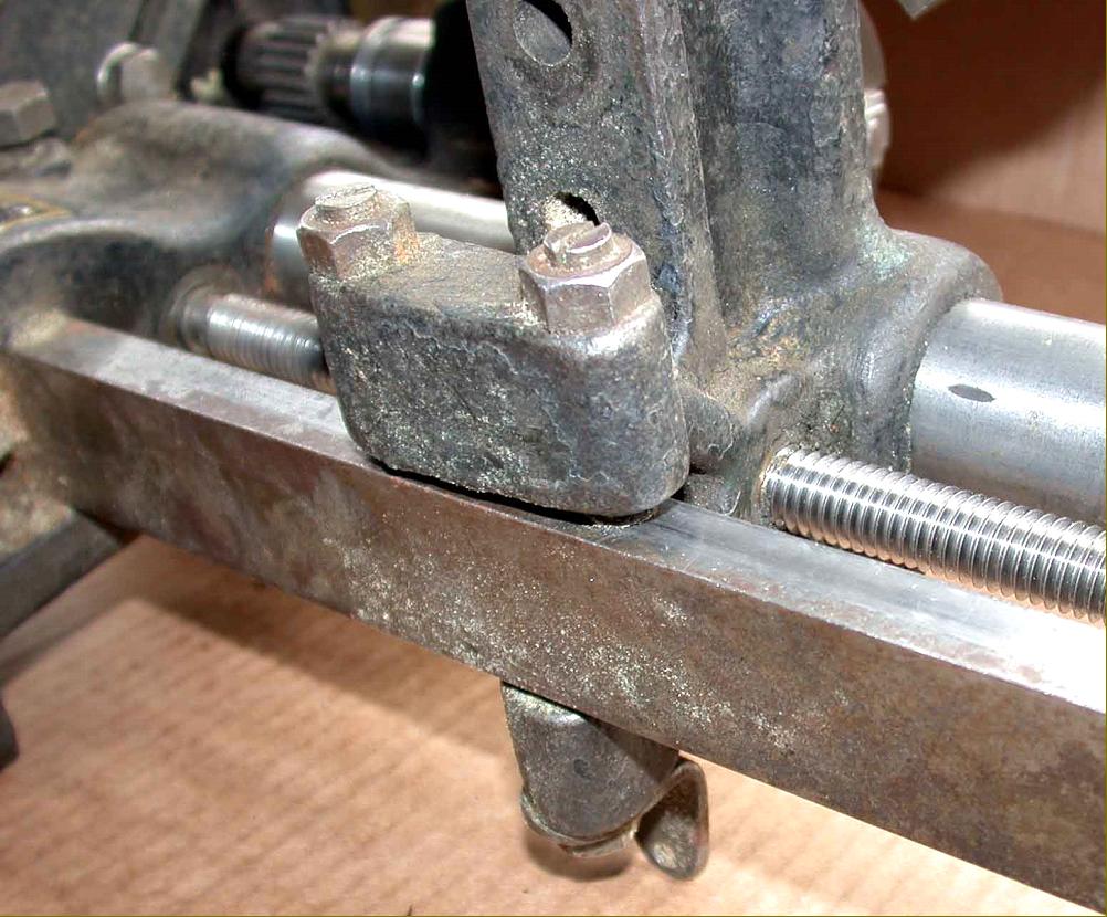
The tailstock barrel was given the usual No. 1 Morse taper, and could be ordered with either a square-thread screw-feed or lever-action barrel with the operating arm arranged to point vertically upwards. Note the slotted set screws (in bronze) screwed into the casting to achieve final alignment with the headstock; this was a method adopted by the makers from the start of production in 1923. |
||
|
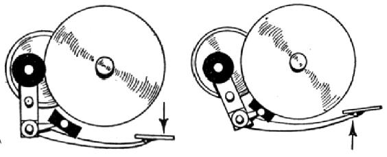
At the 1924 Model Engineering Exhibition the EXE 2.5" lathe was shown fitted to the company's "patented, self-contained friction motor drive" - the patent number for the unit being GB 165/24.. |
||
|
engaged the drive. |
||
|
engaged a spring-assisted brake. |
||
|
Designed to supply power to a bench mounted machine the "Foot-motor" was a self-contained unit |
|
The motor and its bolted-on bracket carried a speed-reducing gear and friction disc. The assembly was so arranged that moving a foot pedal engaged the drive whilst releasing it caused a spring to automatically brake the heavy flywheel to a stop. |
|
|
||
EXE Exlet Lathe A Fine & Original EXE
Home Machine Tool Archive Machine-tools Sale & Wanted
.