|
Continued:
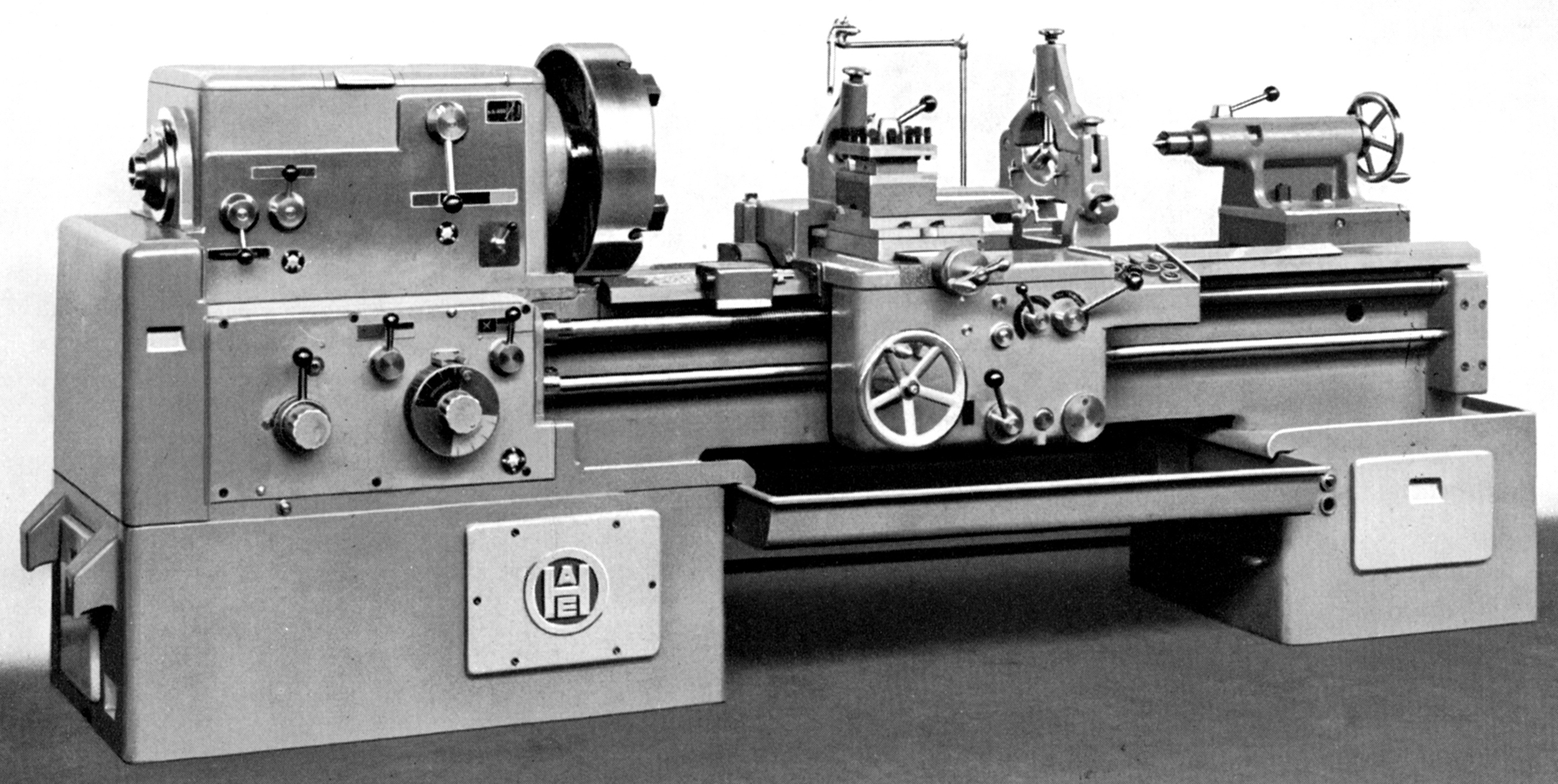
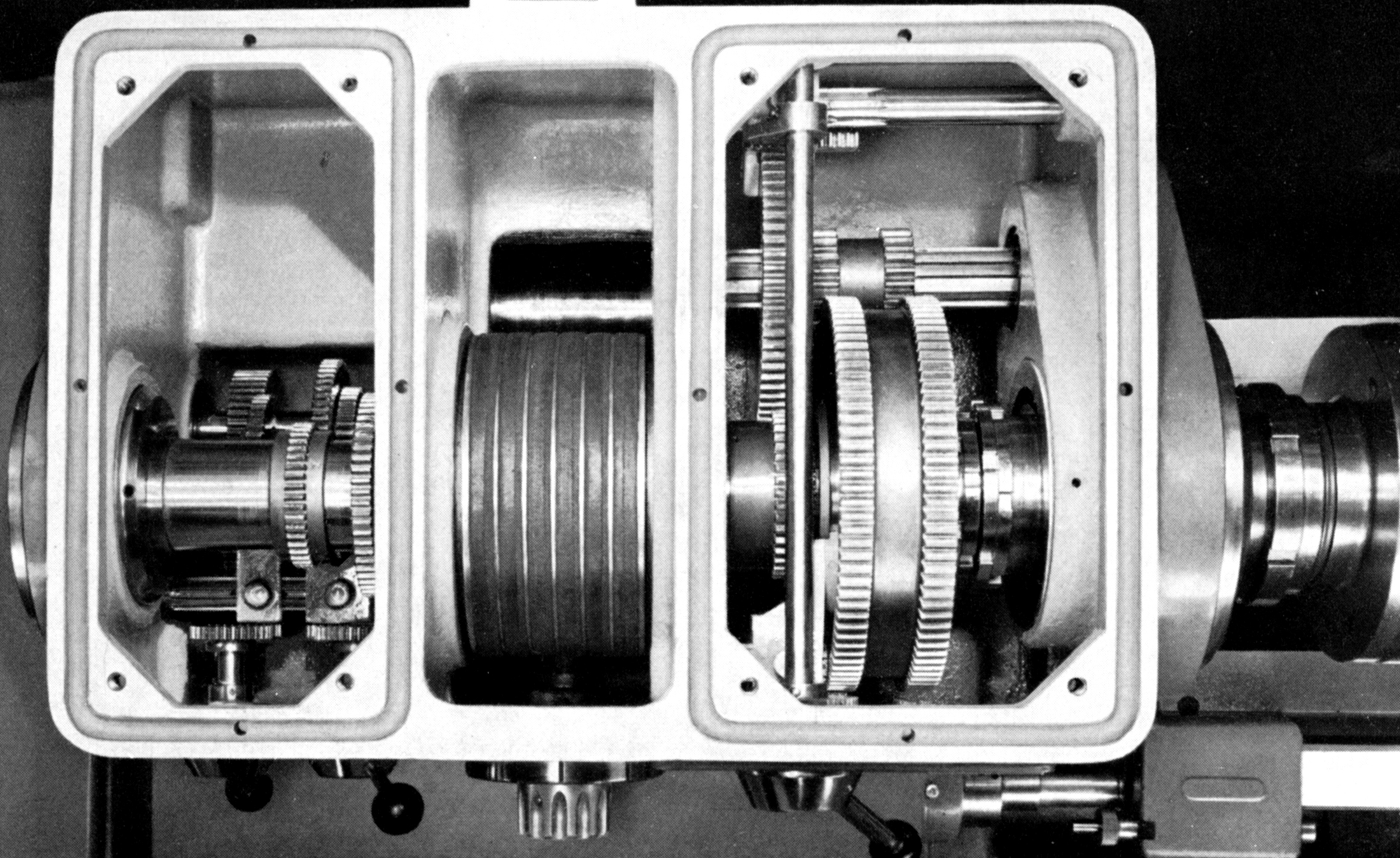
Headstocks of the EF and EFE were identical with oil-bath lubrication, hardened, ground and tooth relieved gears and a 2-inch bore, hardened and ground spindle running in high precision roller bearings - end thrust being taken by two grooved ball races. While the 220 and 250 models had a No. 4 Morse taper spindle, the others all had a No. 5. The multi-V-belt pulley, set centrally on the spindle, ran in its own ball races and was connected to the main spindle drive gear by an internal and externally splined clutch, the arrangement relieving the spindle of belt thrust and vibrations associated with the drive system. Engagement of direct drive - and through the speed-reduction intermediate gear - was by one lever, another providing a means of reversing the rotation of the leadscrew (but not the power-feed shaft, that was done on the apron) and a third for selecting a range of coarse screwcutting pitches.
Screwcutting was by a box of the maker's own design; completely enclosed, it held hardened gears made from a high-quality steel that ran on shafts supported in ball races. All the bearings and the lower gears were lubricated by splash and the upper by a pressure pump. The box had a 10-step pitch change arrangement, together with a 4-step multiplying gear that gave a total of 40 different pitches, these doubled to 80 by use of various changewheel sets e.g. in order to cut English (Whitworth), Metric and modular pitches, a separate set of changewheels had to be mounted for each, an inconvenient arrangement - though this did ensure a better accuracy of pitch than the use of transposing gears inside the gearbox. 80 English pitches could be generated from 9/32" to 68 t.p.i., 66 metric from 0.375 to 6.8 mm pitch and 46 module from 0.125 to 12. Eighty rates of power sliding and surfacing feeds were provided, the former from 0.0014" to 0.34" per revolution of the spindle and the latter set twice as slow from 0.0007" to 0.17". Threads and feeds were selected by a rotating knob on the face of the gearbox and a surrounding reference chart.
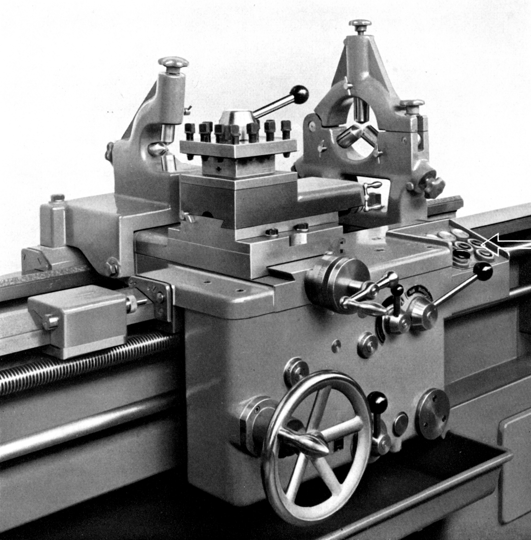
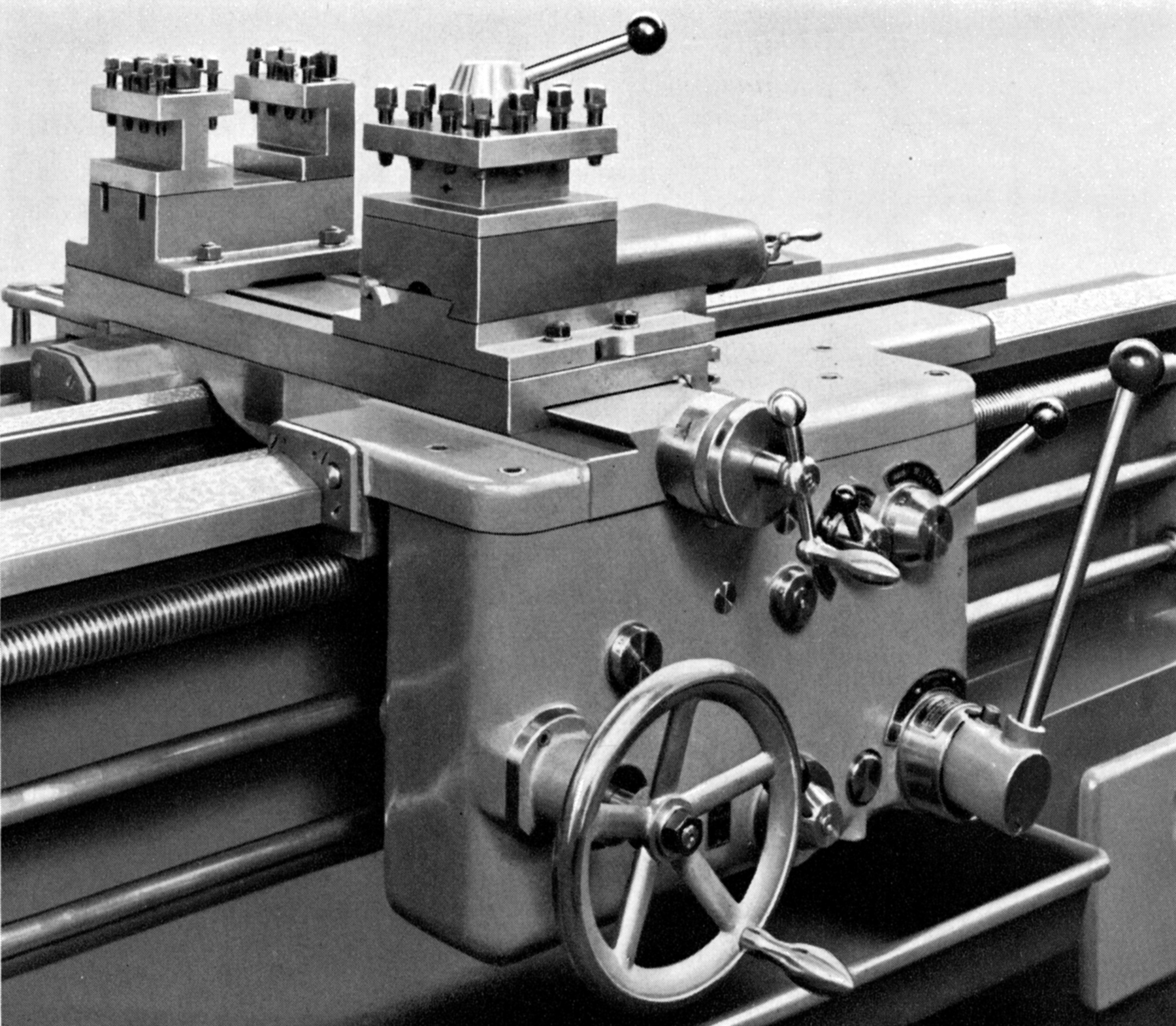
The apron - fitted with an oil reservoir and pump that distributed oil around the inside and also to the bed and cross-slide ways - was protected by the use of a drop-worm mechanism, this being adjustable for the load at which it automatically disengaged and allowed, no matter how high the cutting load, for both the instantaneous manual release of a feed and the use of an automatic. A handy fitting on a large lathe where, on long and slow jobs, the turner's attention might been distracted by the sight of the attractive Miss Evans from the office walking across the shop floor, was the provision of adjustable, automatic trips for both the sliding and surfacing feeds in both directions of travel - the reversal of feed direction being by a knob on the apron itself. As a safety feature, the large carriage handwheel could be disengaged when using the power longitudinal feed.
Fitted with the usual felt wipers, the saddle was adjusted by tapered gip strips - as were the cross and tip slides, these being of quite ordinary, V-edged pattern - though the cross slide may have been fitted, as standard, with two long traverse T-slots to mount a twin-block rear toolpost. The top slide could be rotated through 90° each side of central and was fitted with a simple, triangular tool clamp - though few buyers would have opted for this, choosing instead an extra-cost, indexing 4-way toolpost or one of the recently introduced quick-set type. Both feed-screws on the compound slide rest assembly had zeroing micrometer dials which, while not huge, were of a decent size and given a non-glare, satin-chrome finish. Feed screws could be English or metric, the bronze cross-slide nut being adjustable to eliminate backlash.
Locked to the bed by a lever-operated, eccentric cross shaft, the set-over tailstock had a No. 4 Morse taper, the centre being automatically ejected as the spindle reached its fully retracted position. Unusually for a large lathe, the casting was cut away to form a window through which the spindle's ruler engravings could be read - though there was no accompanying micrometer dial on the handwheel.
Supplied as part of the standard equipment with each new lathe was full electrical equipment, a 4-jaw-chuck-cum-faceplate with hardened, reversible jaws, catchplate, a spare threaded chuck backplate, fixed and travelling steadies with cylindrical jaws and interchangeable tips, a single set of screwcutting changewheels, two Morse centres, screwcutting chart, an instruction manual that included a foundation chart, recommended cutting speeds and lubrication arrangements - and a set of spanners.
Available at extra cost were a number of extras including a hydraulic copying attachment, thread-dial indicator, 4-way toolpost, handwheel-operated draw-in collet attachment, a universal milling and boring attachment, taper-turning attachment for lengths up to 16 inches, a double-type rear toolpost for parting off, quick-change toolpost with three tool holders, coolant equipment, a factory-fitted 9.5-inch diameter 3-jaw chuck, Kienzle speed and feed indicator, machine lighting, sets of turning tools, rotating centres and drill chucks for the tailstock and a magnetic filter for the headstock oil.
If you have an Eriksen lathe of this type, the writer would be interested to hear from you.
|
|