|
Home Machine Tool Archive Machine-tools Sale & Wanted Machine Tool Manuals Catalogues Belts Books Accessories
|
||
|
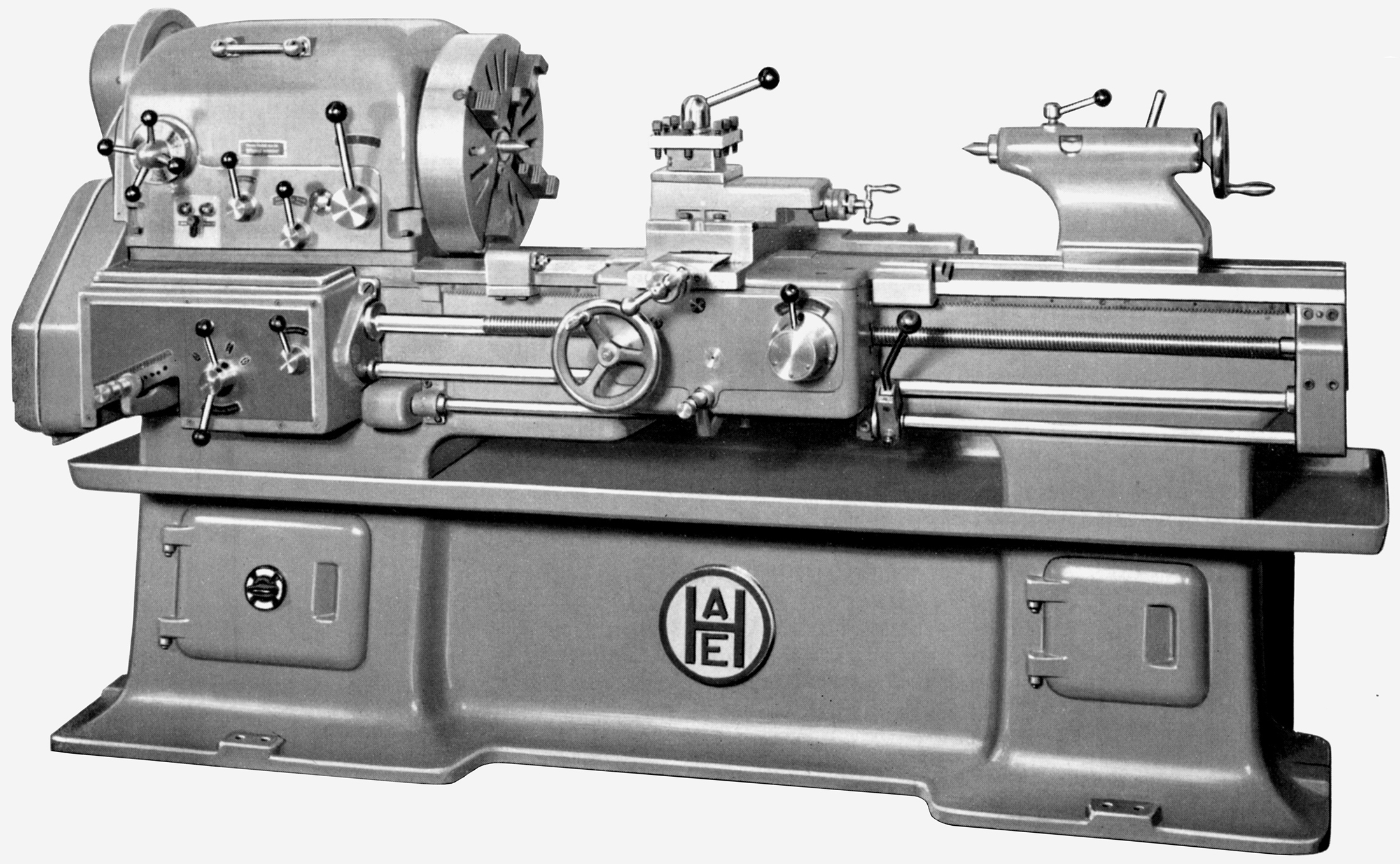
Of an entirely different design and intended for heavier duty use than the 180-DN and 200-DN models, the Eriksen 180-NE and 200-NE lathes were both of identical mechanical specification save for their centre heights, that for the former being 7 inches and the latter 8 inches. Each model was available with a choice of three bed lengths - that gave 40, 60 and 78 inches between centres - all being fitted with a detachable gap piece that, when removed, allowed a workpiece 223/4" in diameter on the 180-NE and 243/8" on the 200-DN to be turned on the faceplate - the depth of the job limited, in each case, to 63/4 ". |
|
save for their centre heights, that for the former being 7 inches and the latter 8 inches. |
|
Continued: |
|
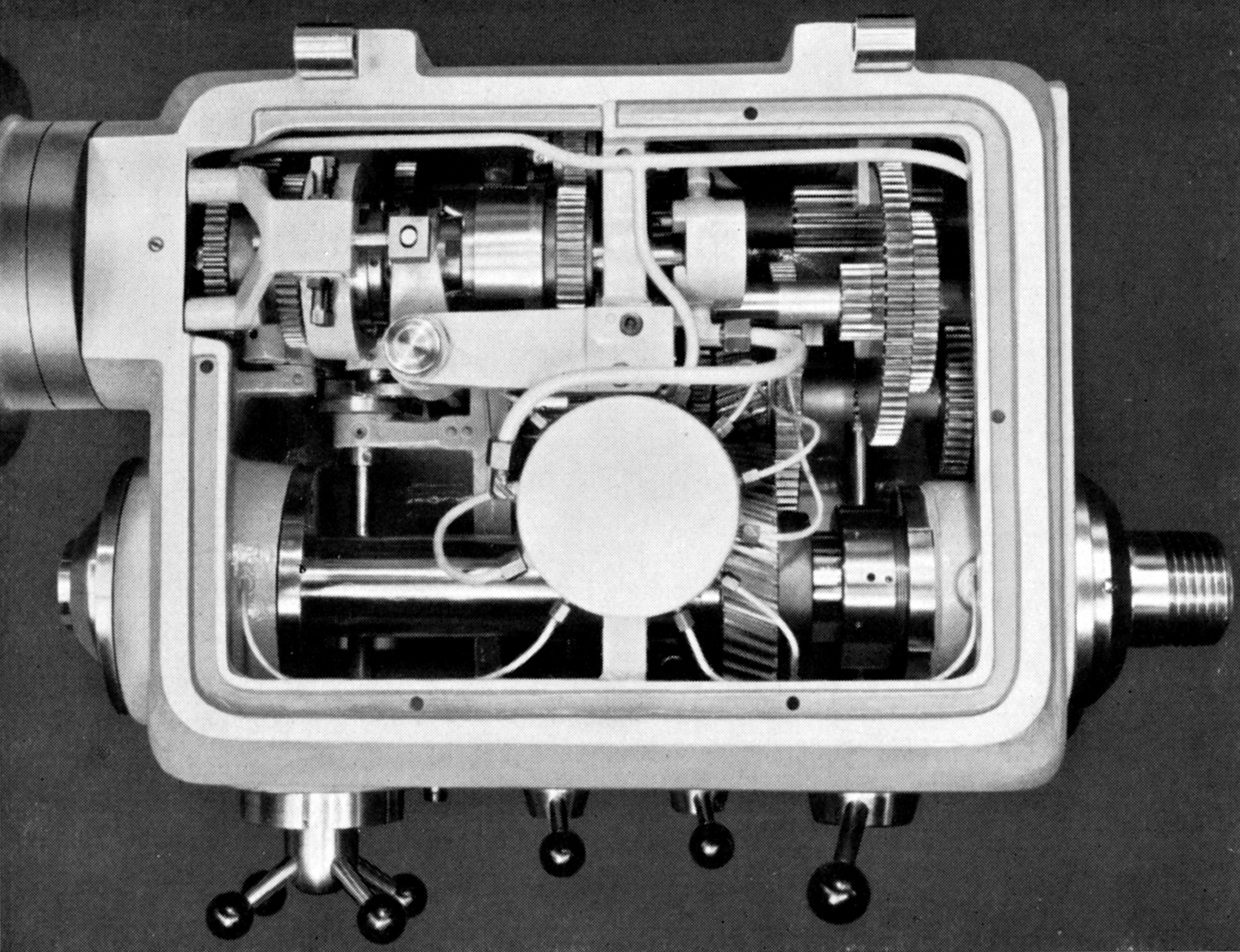
Fitted with hardened and ground gears, the headstock had 18 speeds arranged in geometrical progression at a ratio of 1.25. Two ranges were available, the standard 22 to 1120 r.p.m. or a special version (that incorporated some other modifications) of 45 to 2300 r.p.m. |
|
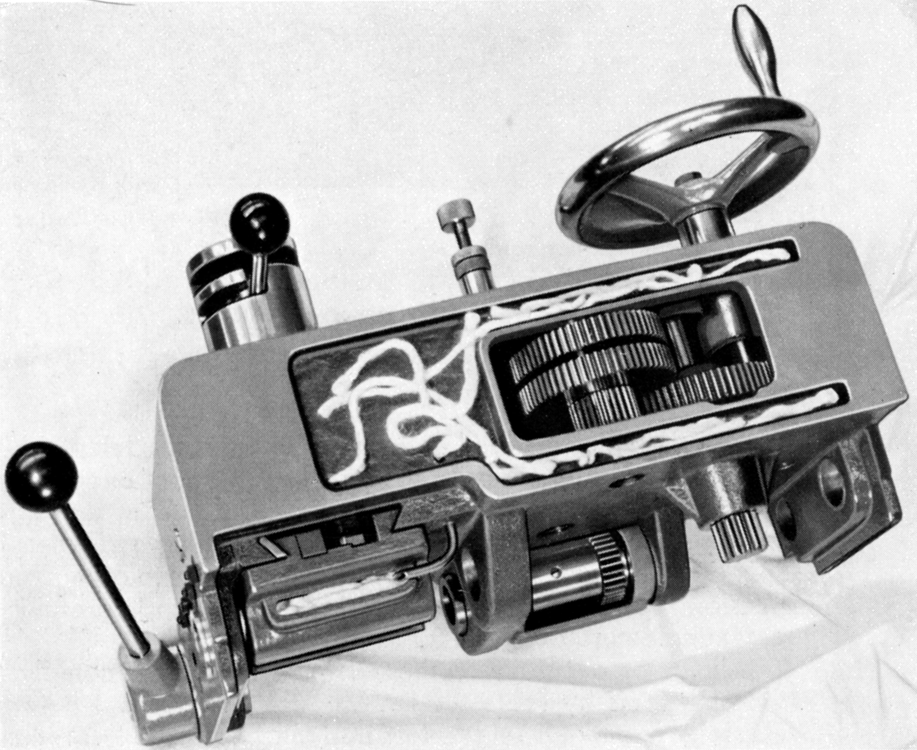
An interesting feature of the apron's was its lubrication system which, as the casting was open at the bottom to accommodate the drop-worm mechanism could not use an oil bath; instead oil was directed by wicks that their supply troughs in which they lay |
||
|
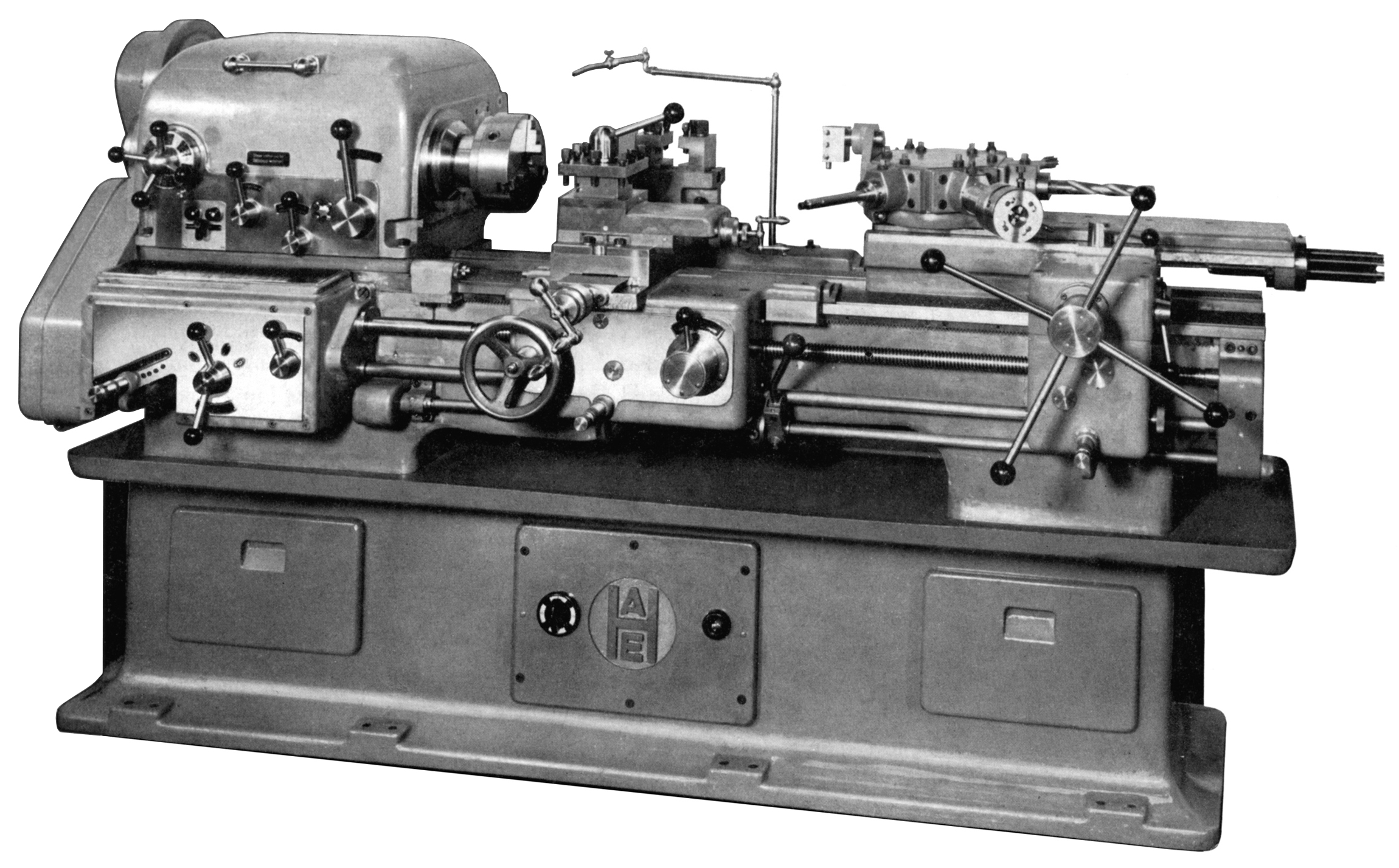
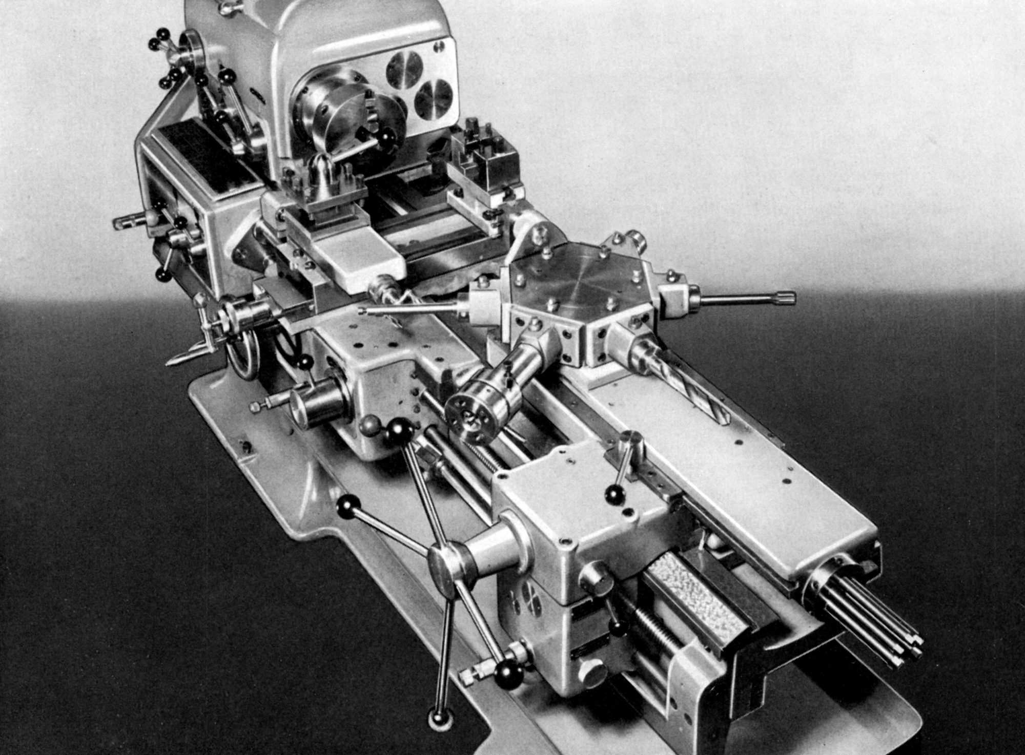
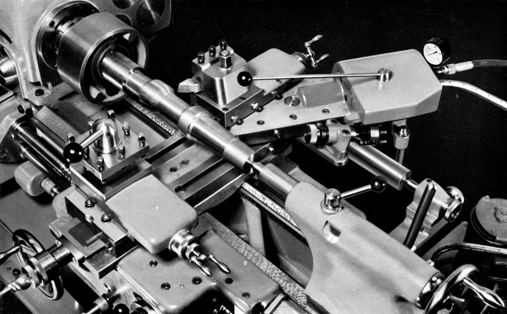
An additional model, the 50/200Rv, intended for production use was also available, this being otherwise as the ordinary models but with the tailstock replaced by a secondary slide fitted with a 6-station capstan head - the whole assembly able to be propelled along the bed using either hand or the power feed shaft. The power-sliding mechanism was identical to that used in the apron of the conventional model and incorporated both the automatic over-load release and the adjustable, pre-set disengage to the drive - this being engineered using radially arranged stop screws that met a fixed stop, so making it possible for each of the six stations to be set with its own length of feed. Turret unlocking and locking was automatic - the first movement of the 4-spoke handwheel released the clamping ring, the next rotated it followed by the ring automatically securing the new setting. As the turret could also be used as a tailstock, the lathe could be quickly adapted back to conventional turning - or the ordinary slide rest used simultaneously with the capstan unit in the setting up of a particular job. |
|
|
||
|
Home Machine Tool Archive Machine-tools Sale & Wanted Machine Tool Manuals Catalogues Belts Books Accessories |
||