E-MAIL   Tony@lathes.co.uk   
Home    Machine Tool Archive    Machine Tools For Sale & Wanted
Machine Tool Manuals   Machine Tool Catalogues  Belts

Colchester Chipmaster Lathe
Colchester Home Page   
Manuals, Parts Lists and Belts are available for all Chipmaster lathes

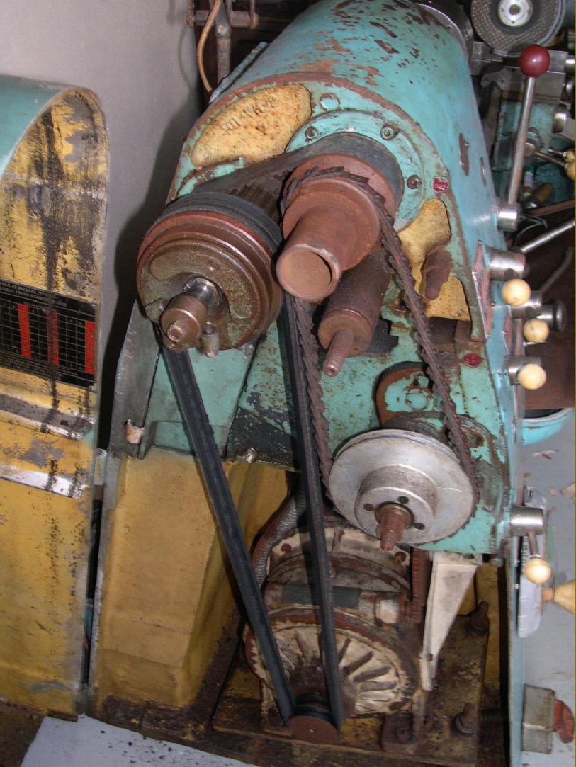
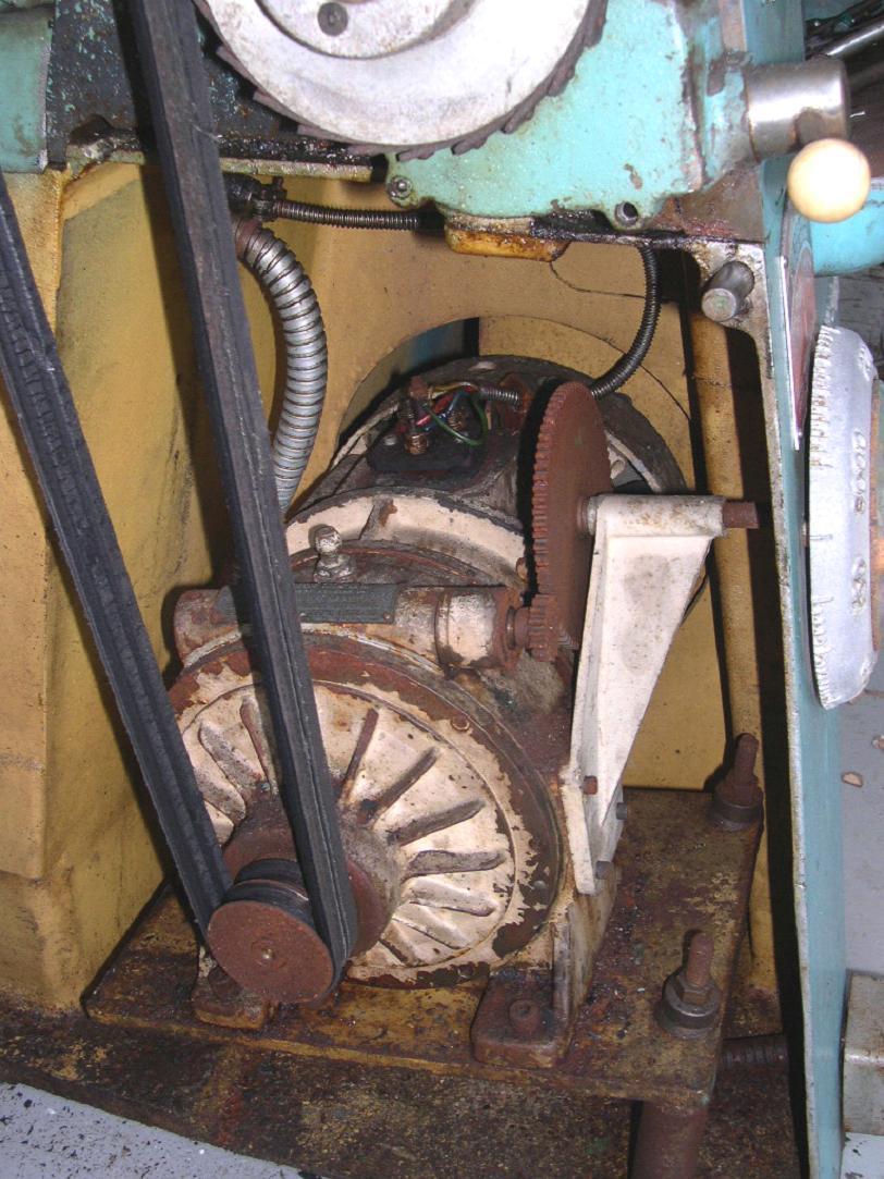
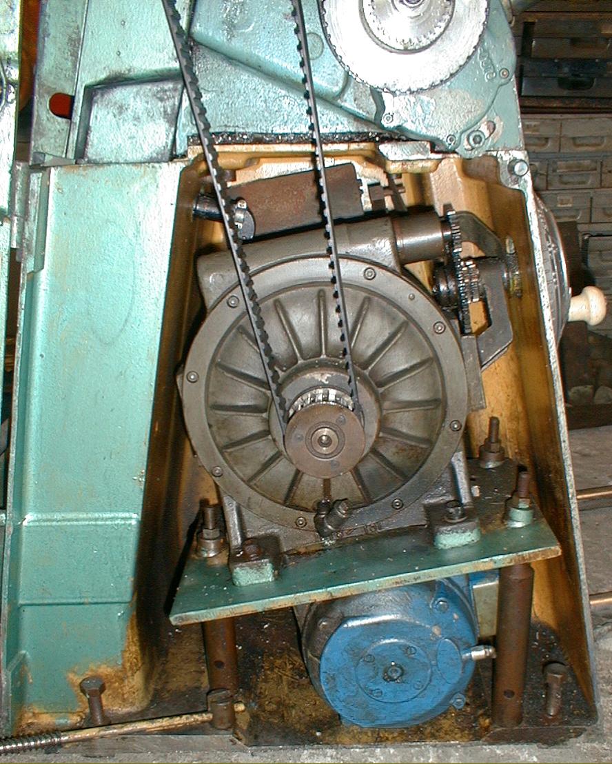
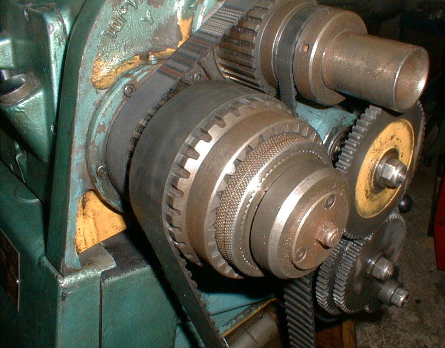
Mounted on its distinctive, wide-base "pyramid" shaped sheet-steel cabinet stand the first 5.75" x 20" Chipmaster, left the production line on July 24th, 1957 - though it had been announced as early as 1956 (Serial numbers are shown at the bottom of this page). The lathe was to occupy an important niche in the Colchester model range (production rates varied between 300 and just over 400 units per year) and remained in the catalogue long after other models from the 1950s had disappeared - the last example being dispatched during 1983.
With its infinitely variable-speed drive and 3000 r.p.m top speed it was intended as a small but versatile high-speed precision lathe and was to form the basis of the later, cheaper and conventionally-driven Bantam. Being relatively complex, the Chipmaster was always an expensive machine - in some years it cost over 46% more than a similarly-specified but larger "Student" model for example - and in 1959 Colchester announced a short-lived, lower-cost alternative version, the "Six-Speed Model" stripped of the variator and with its spindle driven directly from a 3-speed motor rated at 5 h.p., 2.5 h.p. and 1.5 h.p. to gave spindle speeds of: 75, 150, 300, 750, 1500 and 3000 rpm. The lathe was fitted with a distinctive carriage-handle-shaped control (connected to a Stanton electrical switch) in place of the rotating dial of the variable-speed type. The design, construction and detail finishing on a Chipmaster was of an exemplary standard - as it had to be with a top speed of 3000 rpm - and was heavily built, the approximate weight of a standard machine being some 1204 lbs (545 kg), only very slightly less than a Student. The bed, hardened to order only at first but later fitted as standard, was particularly stiff, with chip clearance through elliptical holes that passed to the rear. On its introduction the Chipmaster was fitted with a two-speed motor, but this was quickly dropped in favour of a single-speed version with the speed range set, in both cases, to be virtually identical. At least two generations of this early variable-speed model were made: the first had its 3 h.p. electric motor (though often 1.5 h.p. on those sold to training establishments) and a comparatively small Kopp swash-plate variator constructed as one integral unit with a tall aluminium casting bolted to its side to support the shaft coming from the speed-change handwheel. From the variator the drive passed, using twin V-belts, to a first design multi-plate clutch (thought to be from Colchester's drawing boards) mounted on the headstock input shaft (immediately behind the main spindle) and from there to the headstock spindle by three V-belts on early machines and a toothed belt on all others - the latter element of design then surviving unchanged for the rest of the lathe's production life. These early models are rare, and problems with the drive system, probably concerned with its reliability, must have forced a rethink. On second-generation versions the motor was mounted facing inwards and positioned underneath the plate holding the variator. The latter was now larger, obviously more durable and driven from the motor by a toothed belt with a change to the proven matrix multi-plate clutch. The next stage in the model's evolution was to improve the manner in which variator and motor were mounted: originally, just a simple flat steel plate had been used, supported on three height-adjustable thick-walled steel tubes; the simplicity and comparative lightness of that design suggests that vibration may have been a problem for its replacement was a large and very rigid U-shaped cast-iron housing mounted on anti-vibration pads. Final drive on all models was through a virtually-indestructible Matrix clutch (although on later machines the unit was increased in size) that allowed the motor and variator to continue running with the spindle stopped. On the first two models the cast-aluminium speed-selector dial had an extra plate, positioned above it, indicating that the readings should be halved when running in slow speed. Electrical control was by a handle protruding from the top of the headstock (if wired correctly moving it to the right from the central "off" position caused the spindle to run forwards, moving it left reversed engaged reverse). This lever was, when new, fitted with a transparent plastic ball that glowed red when the machine was running. The clutch was controlled by single lever on the front face of the headstock: moving the lever to the right operated the clutch while pressure to the left engaged a spindle brake. On early machines the clutch lever had no safety catch and accidentally catching it could engage the drive; later models were fitted with an improved, spring-loaded lever that required the operator to first pull the lever outwards before it could be moved sideways.
Continued below:

Late-model English gearbox Chipmaster in its two-tone finish.
The actual centre height was 5.75"

Continued:
The 1
5/16" (35 mm) bore headstock spindle ran in Gamet "micro-precision" taper roller bearings (made by another company in the Colchester group) with the lower part of the speed range obtained through hardened and ground gears. Because the high-speed range was directly by belt, and the comparatively short and rigid spindle so well supported, the lathe had a well-deserved reputation for being able to produce unusually smooth surface finishes. An American-type D1-3" Camlock nose fitting was used, that allowed the lathe spindle to be safely reversed at high speed, and the spindle was sleeved with a hardened 4 Morse taper short sleeve bored to accept a standard No. 2 Morse taper centre (this fitting is often missing, and expensive to replace - though sometimes cheaper replacements are available). Unfortunately, chucks with an integral D1-3" mounting are pricey to manufacture and it is often cheaper (although with only a little saving) to mount a replacement chuck on a new Camlock backplate. Certain precautions are necessary when mounting new D1 accessories on the spindle nose and it may be necessary, in order to achieve maximum grip, to re-set the Camlock studs within them - it is absolutely essential to read the maker's instructions on this point if you are unsure.
All Chipmasters were fitted with a full screwcutting gearbox that offered a greater range of threads than the Bantam. The drive to the gearbox was by changewheels for screwcutting or, for extra-fine feeds, via a V-belt on early lathes and a toothed belt (for a more positive drive) on later models. A lever on front of the headstock - annotated with a belt and gear symbols - selected the appropriate drive. For many years only an Imperial (inch pitches) gearbox was offered, with conversion gears to cut metric threads. However, from the end of 1970 onwards a version with a dedicated metric gearbox was offered. At extra cost the box could be provided with inch-pitch conversion gears, the set comprising: 20t, 24t, 28t, 30t, 36t, 42t, 44t, 46t, 52t, 56t, 57t, 60t, 65t, 69t and 70t. The Imperial box can be recognised by its sliding lever control with indent positions (outboard of the box to the right) whilst the metric box was similar to the unit as used on the Bantam with a joy-stick control in addition to levers. At the end of 1970 an "all-metric" version of the Chipmaster became available and carried the identification "Continental". Fitted with the appropriate translation changewheels English to metric and metric to English screwcutting conversions were possible.
Once in private hands, after hard industrial service, the Chipmaster could suffer problems connected with the drive system; the variator has always been enormously expensive to overhaul and, if it started to produce any untoward noises, they would rapidly assume the volume made by a tumble-drier filled with bell bearings - and if you didn't stop using the lathe, that's more or less what the variator turned itself into. If the variator on the lathe you are considering works smoothly (they are rarely silent), and you decide it will be worthwhile to swap the motor to a single-phase unit, you will find changing it an uncomfortable task. Fortunately, thanks to the wonders of modern technology, a simple solution is at hand - fit an electronic speed-control "inverter". Once in place these units then allow two means of varying the spindle speed: electronically and mechanically - though in practice you will probably find that the electronic method is all you need most of the time. If, however, the mechanical variator on the lathe you are inspecting appears to be faulty, don't worry, you don't really need it. Dump it into the scrap bin (take it apart first and have a look, just in case) and couple the motor up to the inverter you were going to buy anyway. Inverters, unlike simple capacitor-based "converters", provide a variable-output frequency (giving variable-speed drive) and hence obviate the need for any mechanical speed-changing device. They are also inherently reliable - and prices keep falling. The clutch fitted a standard to all Chipmasters not only makes the machine much more pleasant to use but also gives any 1-phase conversion (or electronic control, system) a much easier time.
Some few years ago a friend bought a new, still-crated Chipmaster which had lain forgotten in a store (that's another story). He removed the variator and arranged for the spindle to be driven directly from the electric motor through a 3-phase to 3-phase variable-speed electronic controller. He over-rated it, to give 4000 rpm, and rigged the DC injection braking to make it stop it in a couple of rpm or so (the first time he tried it the motor stopped dead, but the inertia of the rotating parts stripped the drive belt of its teeth.). This machine ran reliably for years, turning out thousands of critically-dimensioned and beautifully-finished aero-space components. For some export markets the Chipmaster was marketed wearing Harrison badges as the Model 10-AA.
Although it took Colchester a little time to get the drive system right, the rest of the lathe remained essentially unchanged throughout its production life - proof that the original design was well thought out and the concept - a machine that could be marketed as a lathe suitable for toolroom, production and general workshop duties - was absolutely right..

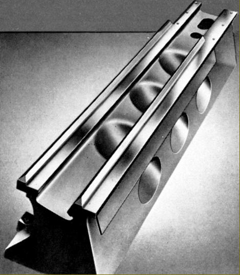
The bed, hardened to order only at first but later fitted as standard, was particularly stiff with chip clearance through elliptical holes that passed to the rear.

Distinctive carriage-handle switch on  the 6-speed Chipmaster

Very rare Chipmaster with six fixed spindle speeds

Early Chipmaster carriage

Early Chipmaster with V-belt drive to the first design of clutch

The first Chipmaster drive system had its Kopp variator bolted directly to the motor

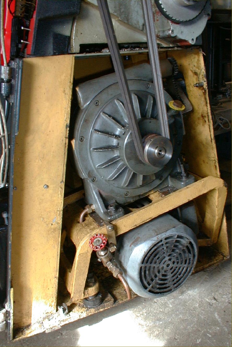
Second-generation Chipmaster with motor and variator mounted on the bottom and top faces respectively of a simple 3-point support steel plate and drive to the clutch by a toothed belt.

Late Chipmaster drive system with rubber-mounted, cast-iron supporting bracket for motor and variator. Note the change back to V-belt drive

Late Model Chipmaster with both gear and toothed-belt belt drive to the screwcutting and feeds gearbox.

Early Chipmasters had a drive to the Matrix clutch by three V-belts and to the screwcutting and feeds gearbox by both gear and V belt. In this publicity picture the V-belt drive from variator to Matrix clutch has been air-brushed out.

  Chipmaster (and Bantam) apron

Chipmaster Screwcutting Gearbox. Lathes with English threading used a different gearbox to those fitted with Metric screwcutting (below); the English box can be recognised by its sliding lever control (as above) the metric box was the same unit as used on the Bantam and had a joy-stick selector (see below). Some "all-metric" Chipmaster lathes carried the identification "Continental". Both the English and metric gearbox could generate, with appropriate translation changewheels, the other type of thread.

Chipmaster "Continental" metric screwcutting gearbox with joy-stick control of a type as also used on the Bantam model

Chipmaster screwcutting gearbox internals

The 15/16" (35 mm) bore headstock spindle ran in Gamet "micro-precision" taper roller bearings (made by anther company in the Colchester group) with the lower part of the speed range obtained through hardened and ground gears. Because the high-speed range was direct by belt, and the comparatively short and rigid spindle so well supported, the lathe had a reputation for being able to produce unusually smooth surface finishes. An American-type D1-3" Camlock nose fitting was used that allowed the lathe spindle to be safely reversed at high speed. Note the toothed pulley, fitted to a spline on the pulley and used to drive the spindle directly on the high speed range.

E-MAIL   Tony@lathes.co.uk   
Home    Machine Tool Archive    Machine Tools For Sale & Wanted
Machine Tool Manuals   Machine Tool Catalogues  Belts

Colchester Chipmaster Lathe
Colchester Data     Bantam     Student & Master    Newer Colchesters