|
While still recognisably based on the earlier Hardinge/Cataract models, the superb-quality millers produced by Hardinge during the 1930s and 1940s were considerable improved. The range consisted of the MD5, a modified and refined version of the original No. 5 with an enclosed drive system inside a compact cast-iron stand; the MD3 and MD4 horizontals with plain or ball-race headstocks (and an unsupported cutter arbor); the BB4, a developed version of the MD4 available with a pre-loaded ball-bearing spindle only and taking 4C collets; a quite beautiful high-speed miniature vertical version, the BB2V that used 2VB collets - and a tool-room horizontal model that could be supplied in either "TM" form as an ordinary universal plain miller (with an optional vertical head) or as the "UM" when fitted with a swivelling table designed to mount a universal spiral dividing head for cutting spirals; both the TM and UM appear to have been sold only as a Hardinge-badged machines and, together with the BB4 and BB2V were the only ones to survive in production after World War 2.
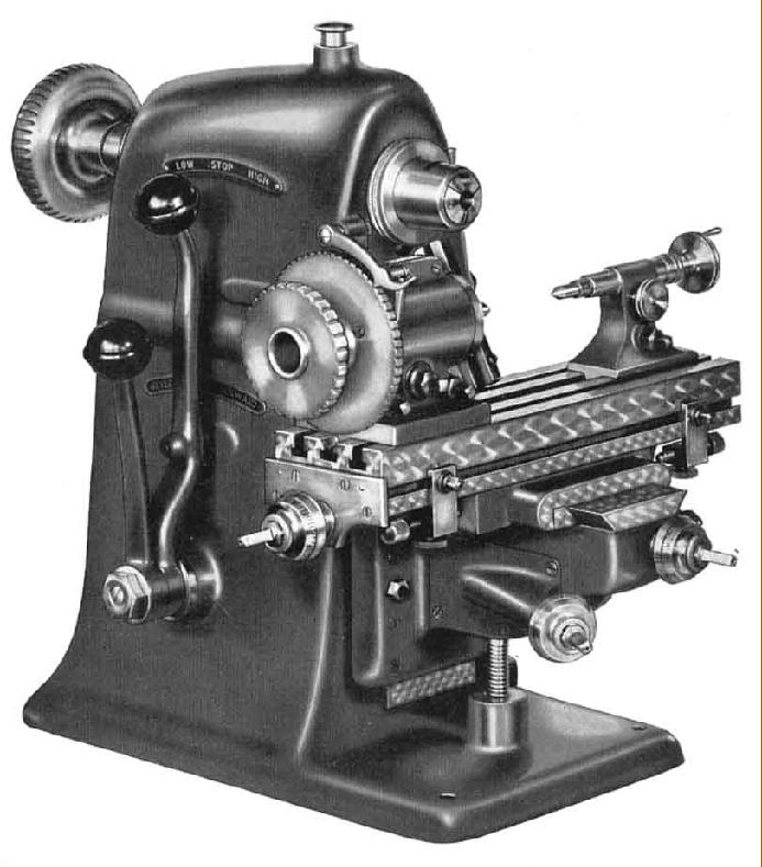
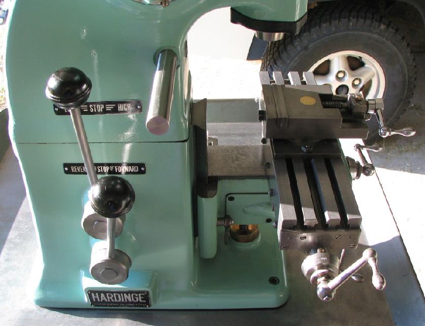
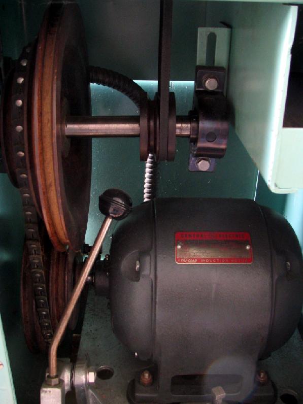
Apart from their collet capacity, the MD3 and MD4 Horizontal bench Milling Machines were identical: the MD3 accepted 3C collets with a maximum capacity of 1/2" while the MD4 was able to take 4C collets with a through bore of up to 3/4". The miller consisted, in effect, of the base section and enclosed headstock from the company's precision bench lathe and, like those machines, could be had with either a plain or ball bearing supported spindle The 6-speed drive system and its controls were identical to the lathe with twin V belts driving the spindle from an under-slung 2-speed electric motor and countershaft unit. The outer of two concentrically-mounted electrical-control levers on the left-hand side of the body selected forwards, stop or reverse with the inner giving the high or low speed range and stop; other speeds were selected by rearranging the belts on the countershaft; the stands offered for the miller were very similar to those for the lathes with a choice of both enclosed and open versions.
Manufactured from the: "finest grade, heat-treated and seasoned alloy iron" the head and base had hand-scraped surfaces to ensure perfect mating; the spindle was made from the best quality ball-bearing steel and hardened and ground both internally and externally; the spilt and adjustable plain bearings were of close-grained grey iron with a high graphite content, tapered on their outside and lapped to a mirror finish on the inside. The makers claimed that this construction was superior to the usual 3°- 45º steel bearing as: "it is mechanically impossible for a 3°- 45º bearing to wear equally - practice has proven this". The speed range of the plain bearing spindle was 180 to 2000 rpm while the optional ball-bearing spindle ran from 230 to 3900 rpm. The twin V pulley was balanced and the spindle end thrust adjustable against a ball race; each bearing was lubricated through an external oil cup fitted with a wick feed to ensure that only oil, not dirt, was drawn up.
The spindle could be prevented from turning by a convenient spring-loaded (lockable) plunger mounted on top of the headstock and (most usefully for a miller) carried in addition to draw-in collets a standard external Hardinge-style tapered nose with quick-release fitting for mounting chucks, faceplates and other attachments.
With hand-scraped ways and positive locks, the table, had a working surface of 12" x 31/4" and carried a central T slot that could both locate accessories and be used, together with the two outer standard T slots, for clamping work. The longitudinal travel was 57/8", the traverse 33/8" and the vertical 53/4"; zeroing micrometer dials with tapered faces were fitted to all three axes of movement and the 1/4" square handles for all table controls were interchangeable. In its originally-advertised form the miller was supplied complete with an indexing head that carried a 60-notch index plate (others were available to order), a tailstock and centre to match the dividing head, a draw-in sleeve tube to hold collets, a swivel-base vise and the necessary handles and wrenches. Extras included a swivel base for the indexing unit and, for the table, a rack-and-pinion lever-operated drive and even a power-feed unit - those these are rare and seldom found. As an option, but not illustrated in the company's sales literature, was an overarm support for the spindle, presumably like that used on the later No. 5 machines.
Continued below:
|
|