|
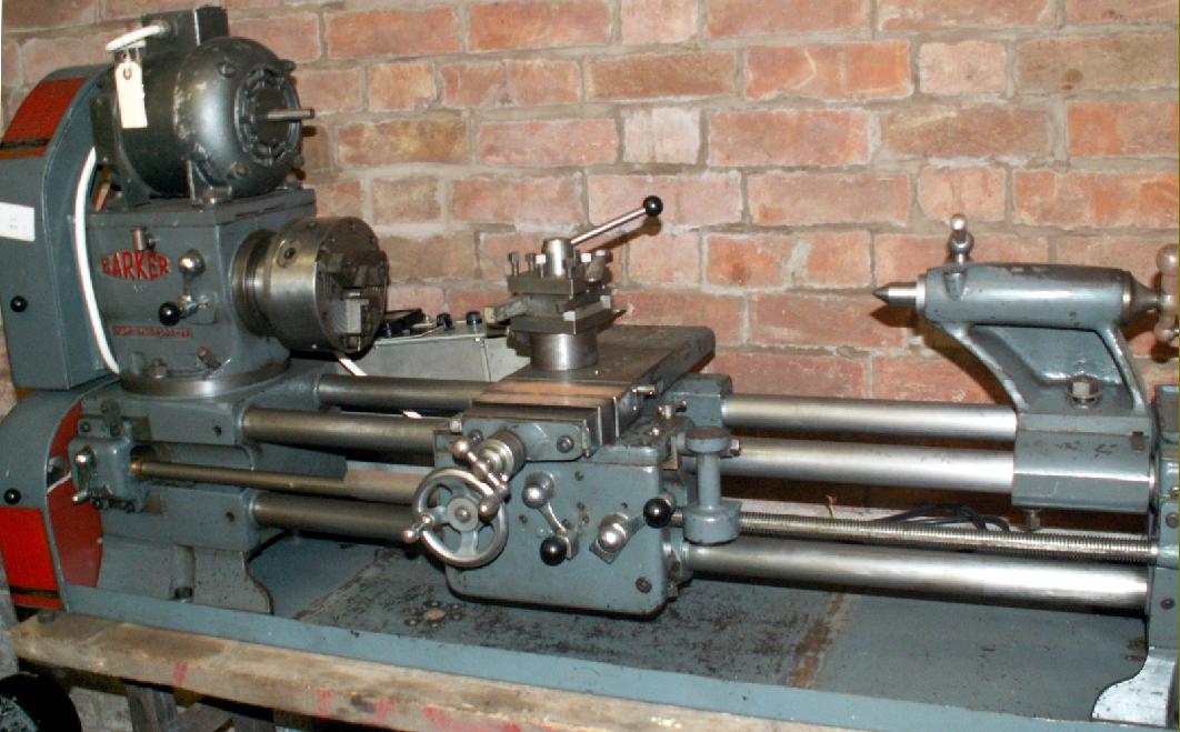
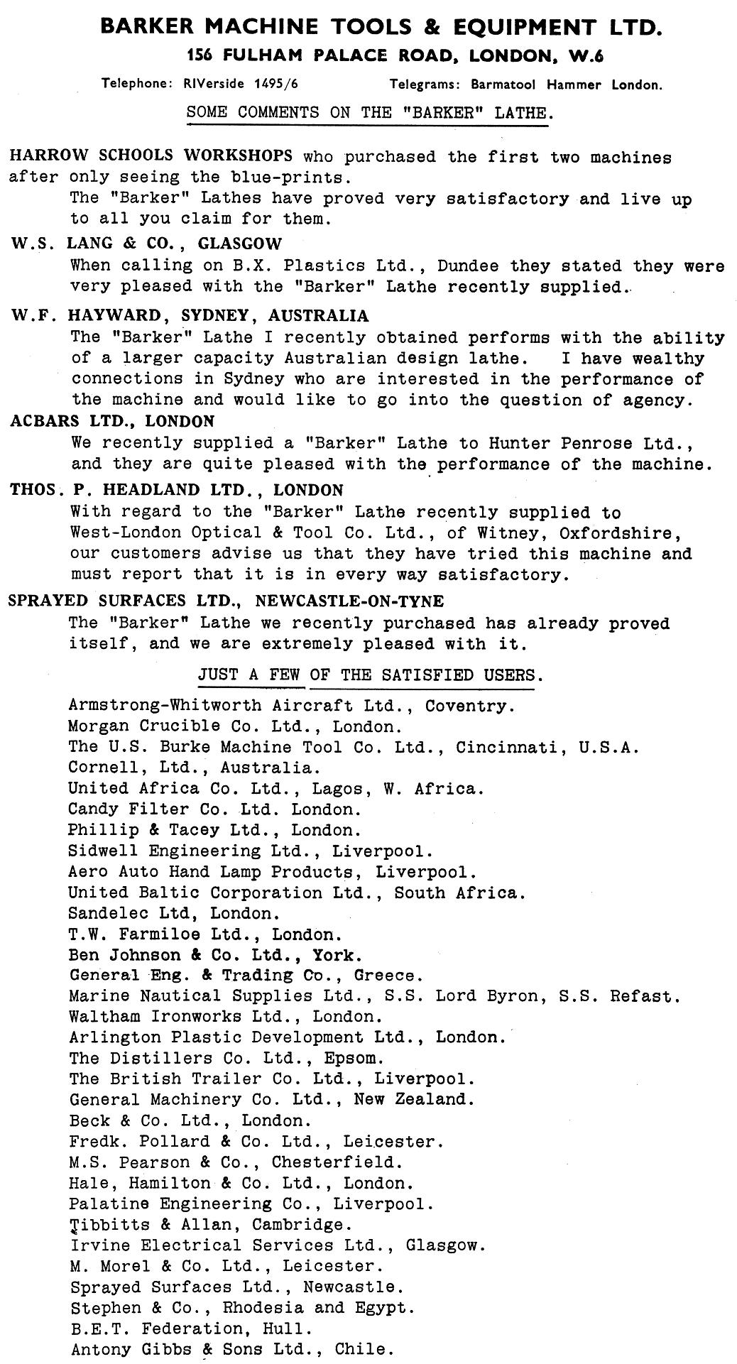
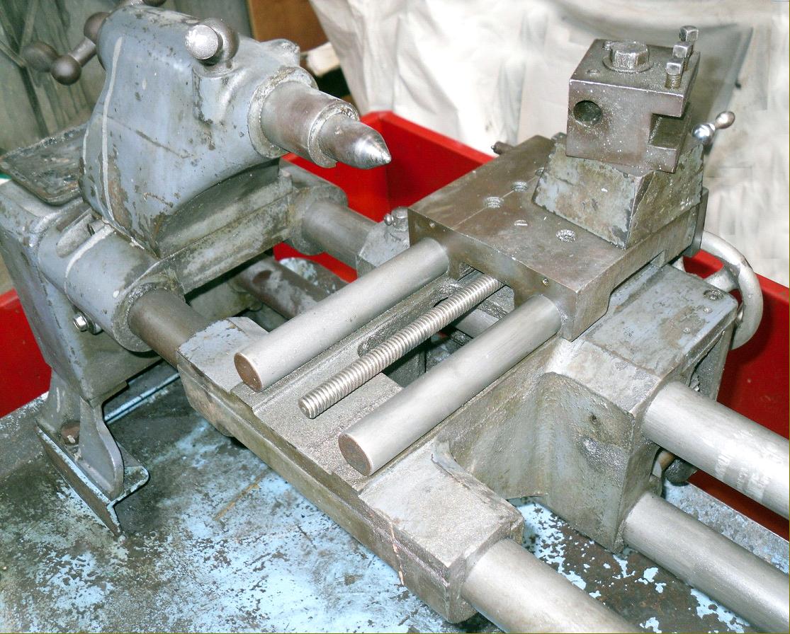
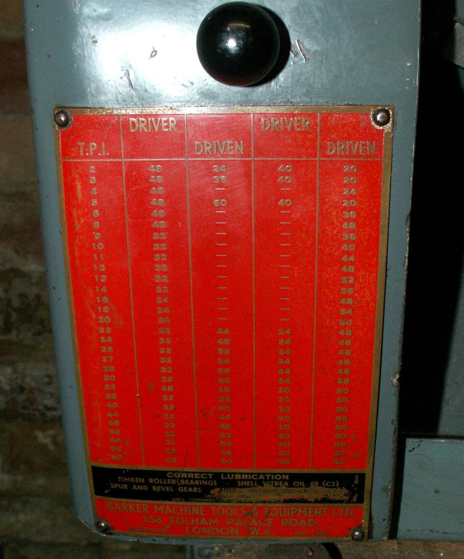
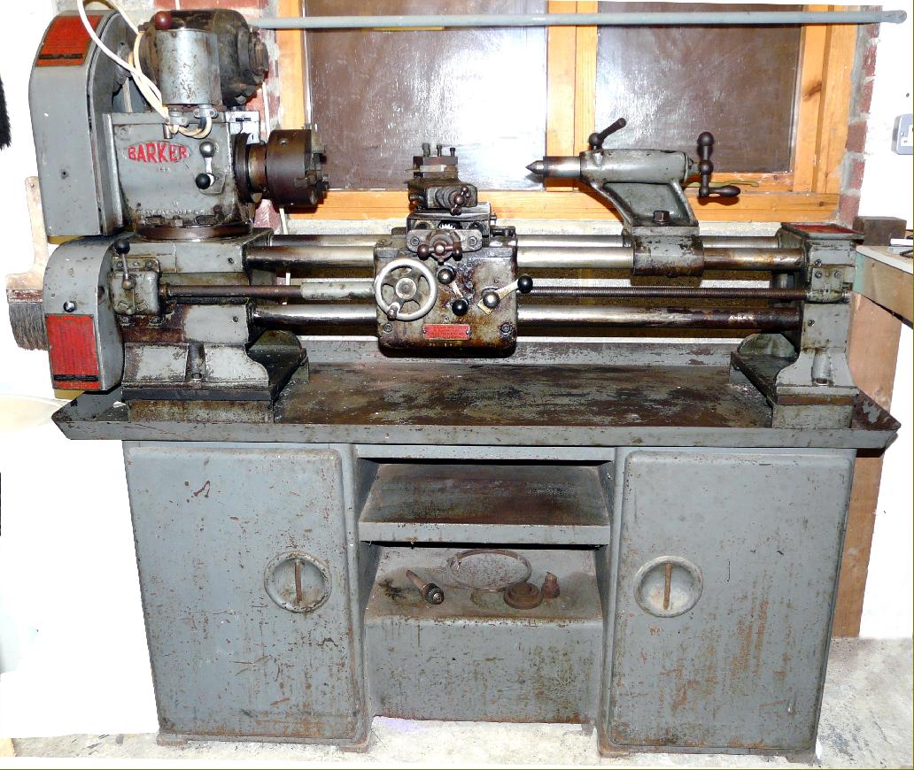
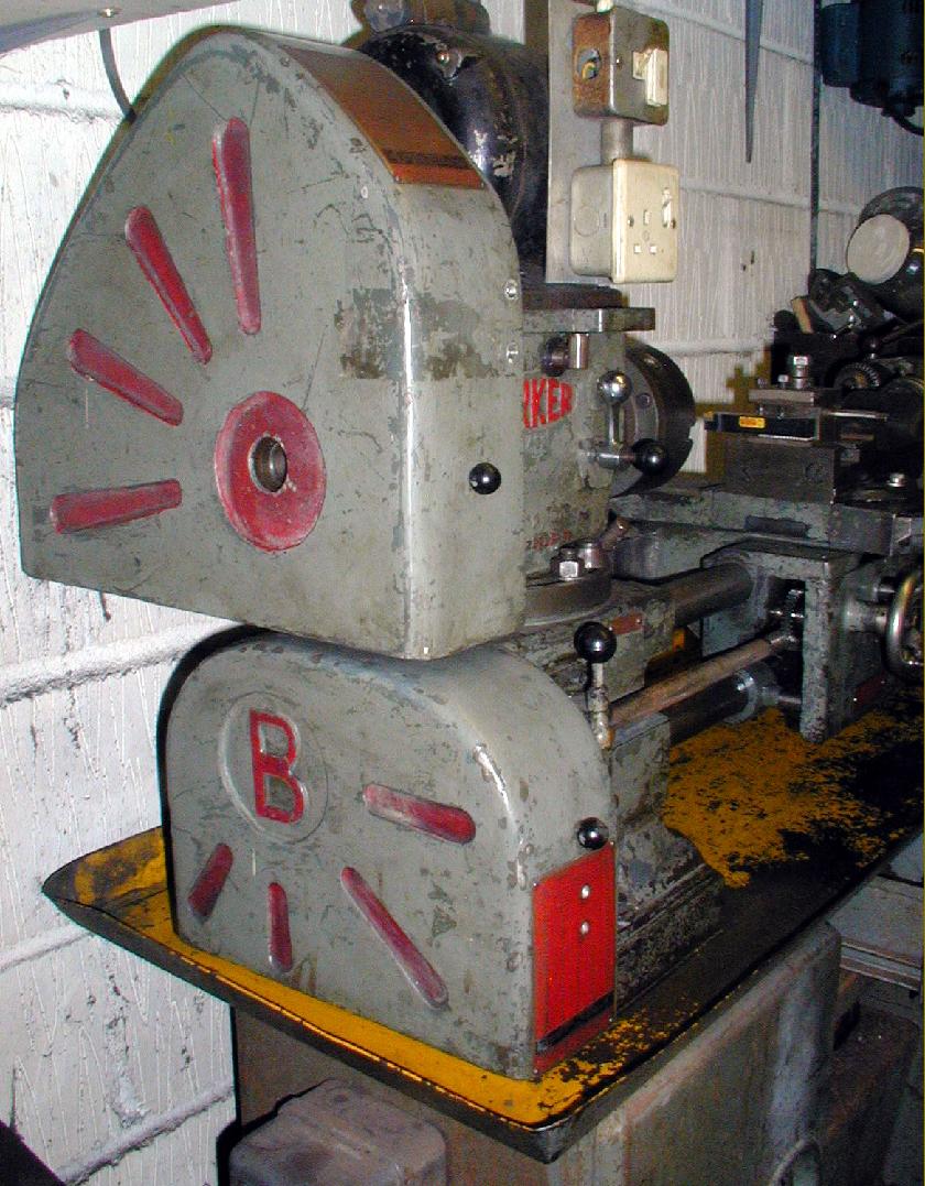
Manufactured during the late 1940s and early 1950s by Barker Machine Tools & Equipment Ltd. of 156 Fulham Palace Road, London W6, the Barker bar-bed lathe was registered under a Provisional Patent No. 2209-47. Of an unusual design, the 5" x 24" (and 5" x 36") machine employed three steel bars arranged so as to provide a stiff "box-section" mounting for the carriage - in principle, if not appearance, rather like a Rivett 608. The bars socketed into cast-iron housings at each end of the "bed" with that on the left forming a heavy base upon which the headstock was arranged to swivel 30° each side of central. The arrangement allowed taper threads to be cut without a taper-turning attachment - and tapered shafts, bores and flanges to be machined under power.
Running in a pair of Timken taper-roller bearings, the spindle was bored with a No. 4 Morse taper - though at 1-inch the bore was really far too small. Chucks and other fittings were carried on a Hardinge-like, quick-lock taper nose whilst a pair of bevel gears under the headstock transmitted a drive out to a conventional arrangement of changewheels carried on a slotted bracket.
While relatively inexpensive to produce, and perhaps using off-the-shelf ground steel bars, a three bar bed lathe suffers from a lack of simultaneous location in the horizontal and vertical planes - the only solution being to employ a forth round bar - or even better a square or rectangular bar with the saddle bearing on one vertical and one horizontal face. However, if the latter had been employed, the designer might as well have removed one of the round bars as the carriage would have enjoyed far better support. Despite these theoretical objections, the Barker still appears to have performed well enough, although perhaps bed wear might have rather changed matters….
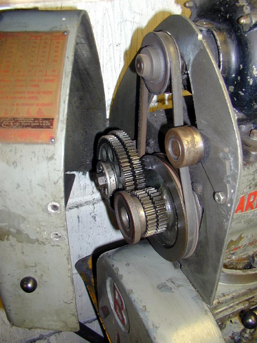
To simplify the problem of fixing a drive system to a swivelling headstock, and to make the machine as compact as possible, the 0.5 h.p. 3-phase motor was bolted directly to the headstock cover plate and drove down through 2-step V-pulleys (with the belt tensioned by a jockey wheel) to pick-off gears that provided a range of 7 speeds divided into high and low ranges; the former (driven from the larger motor pulley at a ratio of 2 : 1) were: 100, 165, 250, 370, 564, 710 and 912 r.p.m. and the latter (from the pulleys at 3 : 1): 66, 110, 169, 246, 375, 475 and 610 r.p.m. (the three slowest speeds in each range being achieved by an additional backgear system built into the headstock). These were useful ranges for what might be considered a rather eccentric design of lathe, but could only by obtained by the laborious and inconvenient means of swapping around, in various combinations, 8 oily gears. Although the standard speed range was rather slow, the makers did offer alternative pulleys and stated that the range of speeds thus obtained could varied between 22 and 3000 r.p.m. Like the screwcutting changewheels, the spindle drive was guarded by a large, swing-open cast-aluminium cover - but neither (in line with the relaxed safety rules of the day), had any form of safety locking mechanism. Although it was charged extra, it is believed that the lathe was always supplied ex-works mounted on a strong, sheet-steel cabinet stand with two large storage cupboards and a deep chip tray. This was probably a wise precaution by the makers for any misalignment of the headstock and tailstock-end bed feet would have so misaligned the three bed bars as to make saddle very stiff to move and badly effected accuracy.
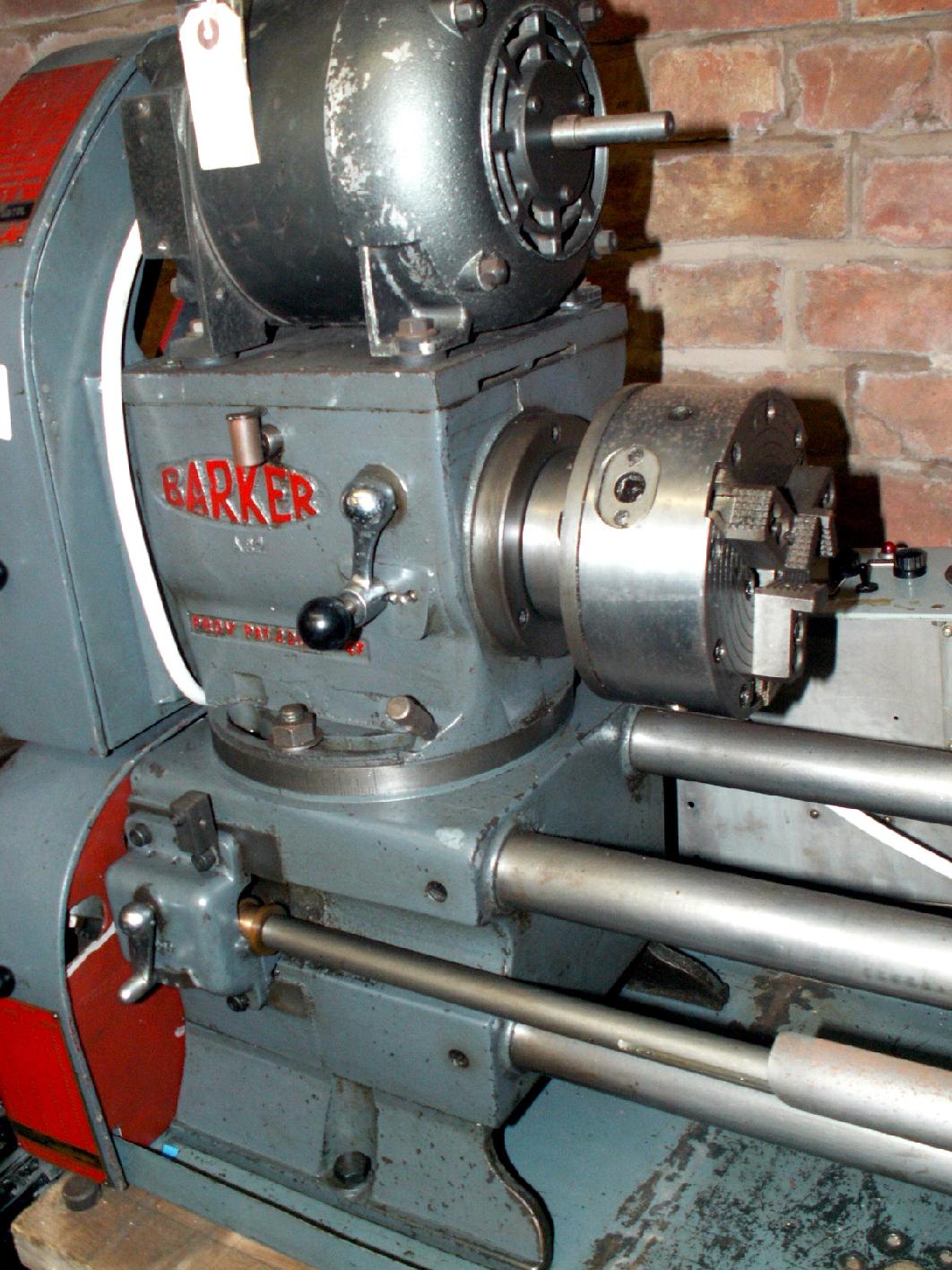
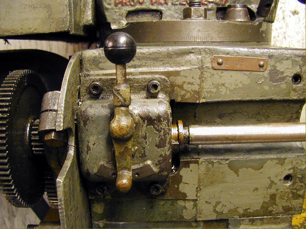
Screwcutting was by ordinary changewheels (a full gearbox was not an option offered) with a generous set of 17 being supplied to generate all the common English threads from 2 to 60 t.p.i. Power for the sliding and surfacing feeds was taken from a keyway in the leadscrew which, in the absence of tumble reverse caused by the unusual headstock design, was equipped with a "reversing gearbox" at its headstock end similar in design to that fitted to the American Atlas 10-inch lathe. Both feeds were selected and engaged by a single 3-position lever on the front face of the apron and, as was often the case with such a simple arrangement, once the feed was engaged the whole mechanism would "wind up" and be difficult to disengage. To get round this, the makers suggested using the leadscrew reversing gearbox to stop the drive with a small plate, riveted to the lathe, instructing the operator how to use the release for the sliding feed: "Use reverse box lever as a dead stop . Traverse lever will then disengage easily".
As standard a typically English style T-slotted cross slide was supplied (that mirrored the bed design by running on two bars) with sliding sheet metal covers to protect the feed screw from swarf and dirt. Strangely - for at the time every ordinary industrial-class lathe was provided with one - a separate swivelling top slide available only as an extra - the lathe below, obviously not fitted with one when new, has been equipped by a previous owner with what looks like the slide from a Holbrook.
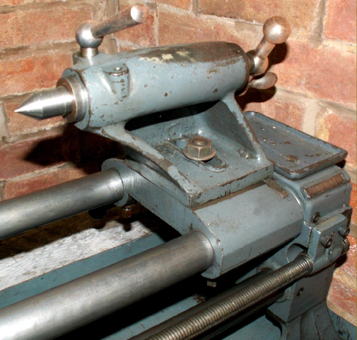
Designed with a usefully exaggerated "lean forward" that allowed drills and other fitting to reach right up to the spindle nose, the tailstock could be set over for taper turning and had, on early examples, a No. 2 Morse taper spindle but, on later versions, a far more suitable No. 3.
Retail prices began, during the late 1940s, at £110, but quickly rose with a few months (due to the usual socialist-Government-caused inflation) to £135 : 17s : 0d. However, this was for a very basic model and by the time 3 and 4-jaw chucks, a top slide, 4-way toolpost, cabinet stand, 2 gears for the slow-speed range, suds pump, fixed steady and thread-dial indicator had been added the final price became a rather more sobering £215.
Having suffered a very hard life the one Barker lathe to pass through the writer's hands needed only the restoration of slideway adjustments, the replacement of the upper front bed bar and a little fettling to once again make it a surprisingly accurate machine capable of taking a decent cut.
Barker also marketed, under their own name, either imported or licence-built copies of the interesting French Siome PMB TC-5 lathe, a machine with an elevating headstock and other features designed to make it as versatile as possible.
Very common on wood-turning lathe - but very much less so on ones for metalwork, other swivel-head engineering lathes include the Hardie and Clement
If you have a Gage lathe - or indeed any other swivel-head metal lathe, the writer would be delighted to feature it in the Archive..
Barker continued below and here
|
|