|
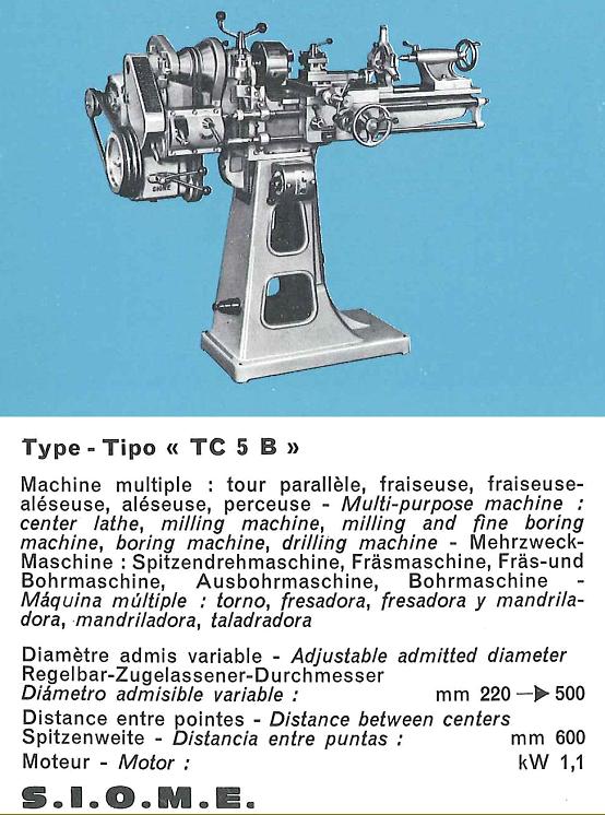
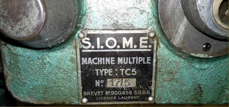
S.I.O.M.E. TC-5 Lathe
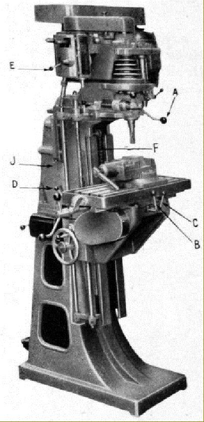
Originally developed for use on board ship, this very unusual and interesting "elevating headstock" lathe was made in the town of Brive-la-Guillarde, France, by PMB (Précision Mécanique de Brives with premises at Rue de la Gare in the district of Malmort sur Corrèze (post code 19360 and phone: 05.55.92.20.49). Believed to have been designed by a Mr. Vives Antoine, around 4000 examples were produced with many sold to the French Navy and to locations where its versatility could be exploited or workshop space was limited. The lathe was also built in a version mounted on a stand that allowed it to be elevated through 90-degrees to act as a vertical miller. In this mode a generously-sized T-slotted table, mounted on an angle plate, was bolted to the cross slide and powered by an extension to the power cross feed drive. Although the original company was eventually to be declared bankrupt, the concept must have been successful for the examples shown below are clearly an early version of what was to be developed (perhaps by a company spun off from the original) into much more highly-developed models marketed as proper multi-function machine-tools.
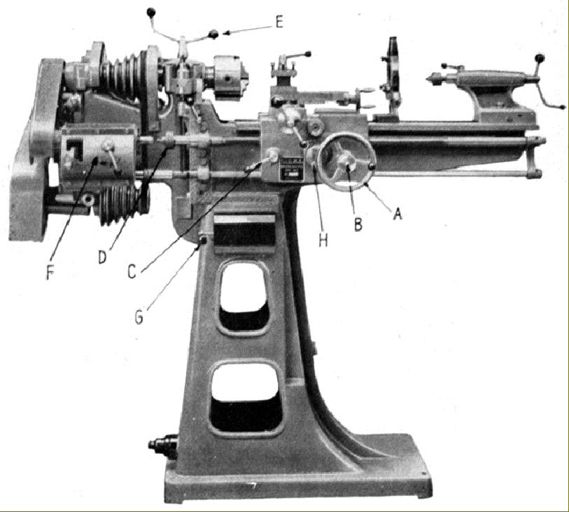
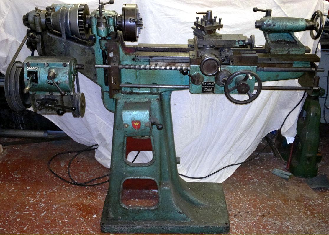
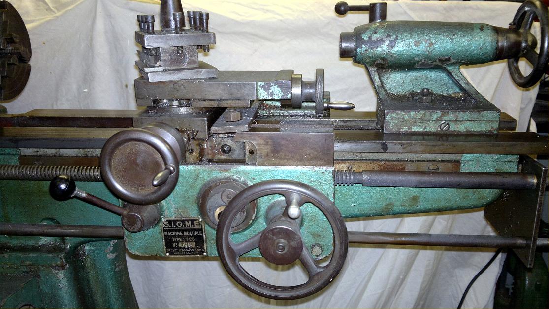
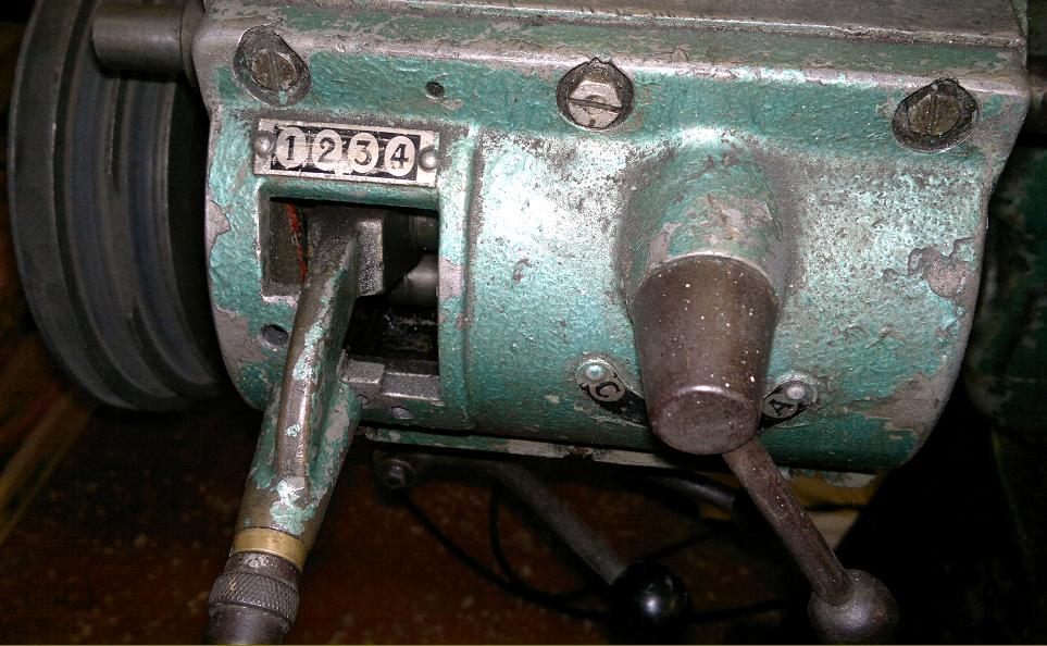
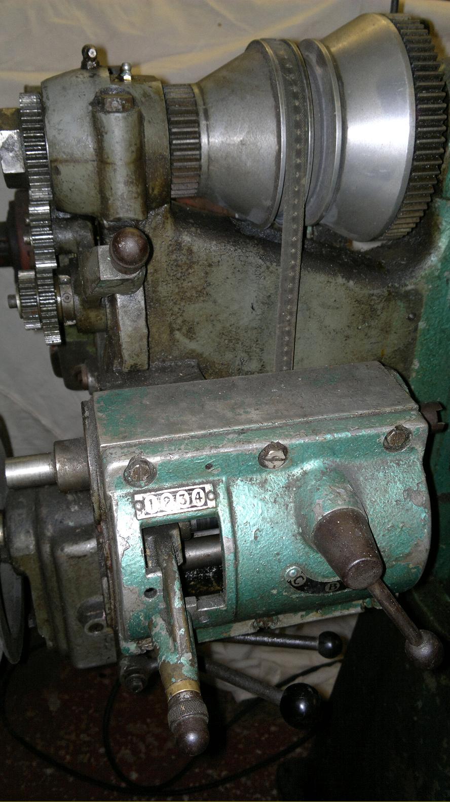
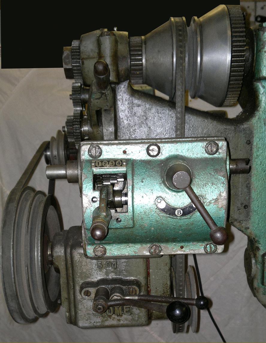
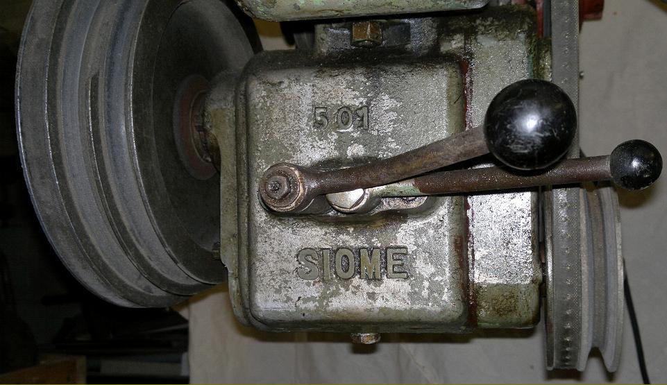
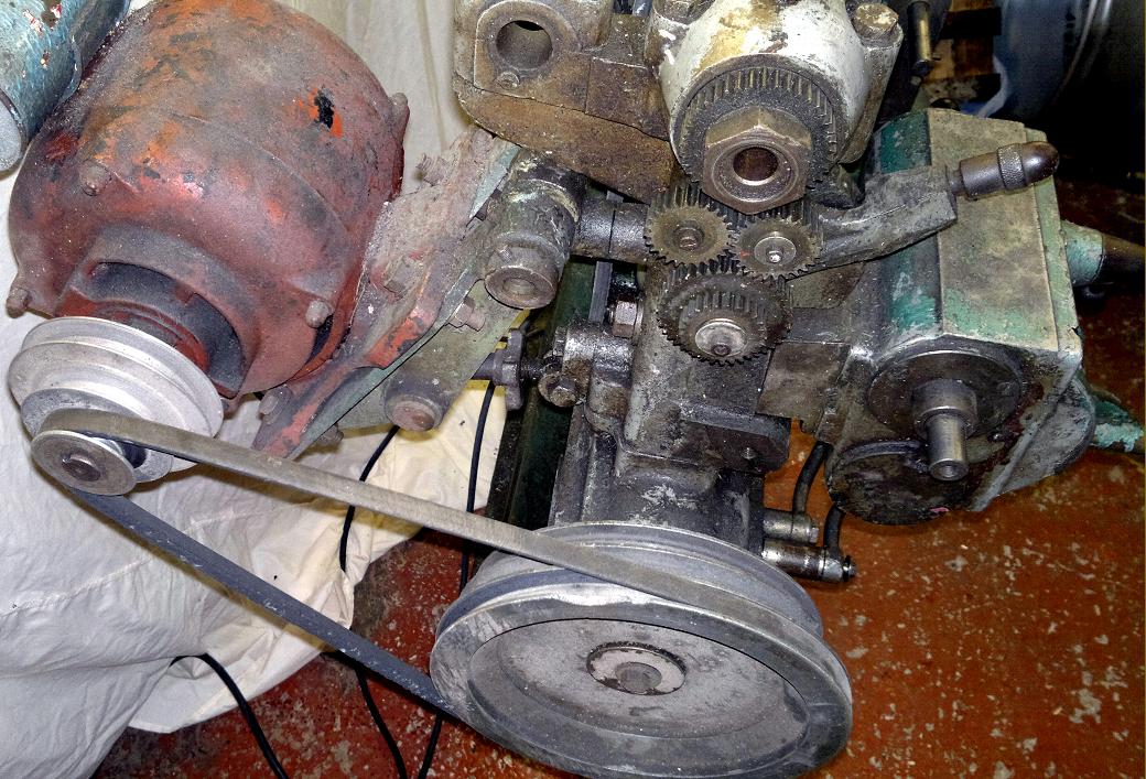
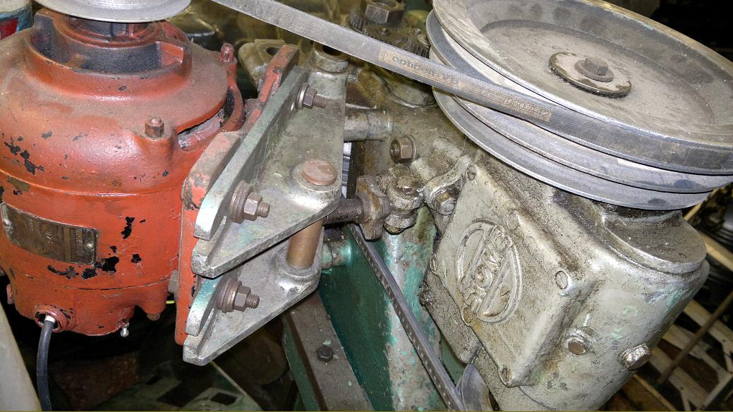
Of approximately 5-inch centre height, and 20-inches between centres, the lathe had an English-style, flat-topped, right-angle edged bed of the cantilever type with its very deep central section bolted to a cast-iron "trumpet" stand. The headstock end of the machine was separate and, being connected to the bed by a vertical slideway, could be raised and lowered by a screwed rod with its control handle set just above the level of the headstock. The plain-bearing main spindle, fitted with a conventional backgear assembly, was driven by a pair of V-belts from a gearbox unit (bolted to the underside of the headstock), with a motor carried on an adjustable plate pivoting from its back face. A conventional a tumble-reverse mechanism and changewheels took the drive from headstock spindle to screwcutting gearbox - a unit fitted with a 4-position lever tumbler and a 3-position quadrant lever - an arrangement that gave 12 pitches for each setting of the gears. The leadscrew, used only for screwcutting, was fitted with a dog clutch in a sleeve that allowed it to be disengaged when the head was elevated. However, in order to provide power sliding and surfacing feeds (no matter what the position of the headstock), the power shaft was equipped with sliding splines and universal joints, rather in the manner of the drives fitted to many milling-machine tables: this mechanism, though not visible in the picture of the lathe, can be seen below in the illustration of a similar machine arranged as a vertical miller.
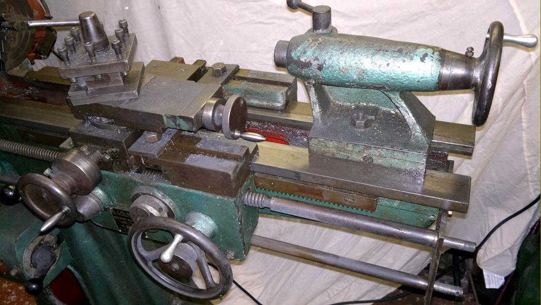
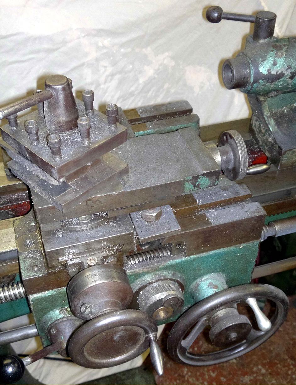
Although the saddle was a decent length the fact that the bed ways could not be arranged to run past the headstock meant the cross slide had to be offset well to the left in order to let the tool reach right up to the spindle nose; this left two long right-hand saddle wings that the maker had equipped with longitudinal T-slots.
It is likely that the maker would have provided a range of raiser blocks to position under the top slide in order to allow turning in elevated-height mode, and it may be that even a version of the special tailstock-barrel clamp issued with later models might also have been available.
If you have a TC-5 lathe, or any sales literature or information associated with the makers, the writer would be interested to hear from you.
|
|