email: tony@lathes.co.uk
Home   Machine Tool Archive   Machine-tools Sale & Wanted
Machine Tool Manuals   Catalogues   Belts   Books  Accessories

Atlas 6-inch Lathe Mk. 2
Atlas 6-inch Mk.2 continued here

An Operation Manual and Parts List is available for
the Atlas 6-inch Mk. 2 lathe


Atlas 6-inch Mk. 1 Home Page

Atlas 6-inch Mk. 1 Photographs   Atlas Home Page
     
Atlas 9, 10 & 12-inch Lathes   Atlas Miller   Atlas Shaper

Atlas 6-inch with Screwcutting Gearbox   A Restored Model 612


By 1974, and after 37 years of production, the Mk. 1 6" Atlas had been extensively redesigned as the Mk. 2 and was now catalogued by its makers first as the Model 3950 with a headstock made from cast iron and then, as the 10100, with one in ZAMAK (of course, the lathe was also sold by sears under their Craftsman label as well). Although the bed, complete carriage assembly and tailstock were conventional enough, the use of a pressure die-cast headstock on the last few models made broke new ground, the design featuring a very short assembly that held an unusual and compact backgear arrangement - of which more later.
In an effort to keep the price competitive, on the home market the Mk. 2 was sold only direct from the factory with two versions being available - Imperial (inch) and metric. The latter machine, known officially as the
Atlas 150, was able to cut only metric threads - of which 23 were available from 0.1 mm to 3.0 mm. The leadscrew, cross feed and top slide screws were also of metric pitch and the feed dials, tailstock barrel, threading chart were all calibrated appropriately - in other words, a complete and proper metric machine rather than just a simple screwcutting conversion.  The version with English calibrations offered threads between 8 and 96 t.p.i. (or optionally, at extra cost, from 5 t.p.i.) using, in addition to ordinary changewheels, a novel and ingenious system of "Gearsettes" - combinations of changewheels (sold in 6 different sets) marked with a circular metal disc that indicated the thread and feed range - together with an indication of which other gearwheels would mesh with them to provide the correct set up. As a comparison the Myford ML7 will only cut down to 8 t.p.i. with the changewheel cover closed - if coarser threads are required the cover has to be left off and gears larger than 75t used on the exposed bracket.
From Serial number 000100 to 007327 there was no way of adjusting backlash in the carriage handwheel and rack-gearing assembly - but from machine 007327) a modified part was introduced that allowed this to be taken up, However, the Company records appear to be wrong, for examples have been found of late serial number machines still fitted with the earlier parts.
A major change on the Mk. 2 involved removing the expensive countershaft assembly, as used for decades on the Mk. 1, and bolting the motor directly to the bench behind the lathe. The headstock pulley was fitted in an overhung position, on the outboard end of the 17/32" bore, 1" x 10 t.p.i.  spindle, with a simple jockey pulley to tension the belt that slid on a stud fitted above the belt run. Unfortunately this "modern" method of engineering the headstock drive had the effect of reducing the number of spindle speeds from 16 to 8 - but with a still-respectable range of 55 to 2300 r.p.m. when using the maker's recommended 1/3 hp 1725 r.p.m. 60 cycle motor. Although the Emco Compact 8, Myford 254 and various modern Chinese lathes also use a similar drive system, they were not the first makers of small-lathes to employ this cost-saving set up, the EXE Company of Exeter, England, used the same arrangement on their models during the 1930s, as did several makers of cheaper, less highly-stressed wood-turning lathes. Original headstocks were equipped with Japanese-manufactured NTN ball bearings, these being changed, after a couple of years, for Timken tapered-rollers. Astonishingly, some late versions of the Mk. 2 were built with a headstock die-cast in  ZAMAK - with walls of hopelessly inadequate thickness. The result was a machine quite unable to cope with the stresses of ordinary turning, especially after some months of use, and was prone to the headstock cracking round the clamp studs. Replacements, in cast iron, have been available for some time, and effect a complete cure. However, rather oddly, the new units come with a larger diameter spindle and it's necessary to turn down the outer end in order to mount the gears and pulley from the original. To adjust the spindle end float, instead of a screwed ring, that in the cast-iron headstock has a simple push-on distance piece secured with 2 set-screws. If any reader has experience of using the version with a ZAMAK headstock, the writer would be interested to hear from you.
To save even more money, the design of the carriage (with saddle and apron cast as-one) was carried across unchanged from the Mk. 1, though new patterns were used that gave a more modern, square-edged look. The cross slide was still of the "short" type (which wore just the central portion of its ways) and the saddle-to-bed gib strip was fitted at the back where, though far less complicated to engineer, it provided a flexibility that would have been absent if the saddle had contacted the back of the bed directly. Although, with its chrome-plated handles, the compound slide rest looked very handsome, lurking beneath the surface was a drawback: the gib strips were made of plastic and the metal-reinforced dimples for the adjuster screws tended to snap. This did not affect the side-to-side play by allowed the slide to lift when a heavy cut is made; making, or having made, a new set of metal gibs is the obvious, low-cost solution.
An interesting point concerns the steadies: while the travelling (follower) steady was unchanged from the used on the Mk. 1 6-inch, the fixed steady (
steady rest in the USA) was given round fingers in place of the original flat and the adjuster screws changed from 1/4" to 3/8". Although these alterations involved the use of a new, more modern-looking casting, as the bed section of the Mk. 1 and Mk. 2 lathes was identical, each steady should fit the other without difficulty.
Able to be set over for taper turning, the tailstock was solidly built and, happily, used a proper compression fitting to lock the 3/4" diameter spindle. The travel however was only 1.25 inches and the Morse taper a No. 1 - these (together with the very short cross slide) being the only serious specification failures in an otherwise well-designed little lathe sold at a price affordable by the amateur machinist. On its introduction the lathe was painted in a traditional machine-tool grey but at some unknown point, before production ceased in 1980, this was changed to a bright blue.
The Mk. 2 Atlas was 34" long, 17" deep and stood 11 inches high; it weighed approximately 92 lbs without its (extra-cost) electric motor.  Pictures continued here


The outboard drive system as fitted to the late model Atlas 6" lathe. Instead of  engineering a system whereby the motor could be moved to release the belt tension (when a change of speed was required) a simple adjustable jockey pulley was fitted above the belt run.
Before the backgear assembly can be brought into operation the 4-step pulley must be released from the shaft by pulling out a small ring on its end.  See the detailed drawing below.

Engaging backgear on the Model 101 Atlas 6" lathe. At first sight there is no obvious way of releasing the large V pulley from its embrace with the spindle. The secret is the "external locking ring" on the end of the pulley; this is simply pulled outwards to uncouple it from the shaft and the backgear lever then operated as usual to mesh the respective gears.


Neat and secure (if slow to remove and replace) changewheel and headstock drive-belt cover.

Rear view of the very short headstock. The aluminium handwheel was used to adjust the tension of the jockey pulley.


To tension the belt, in the absence of any means of  moving the motor, a simple adjustable jockey pulley (top left-hand corner of the picture) sliding on a stud, was fitted above the belt run. Unfortunately this "modern" method of engineering a headstock drive had the effect of reducing the number of spindle speeds from 16 to 8 but with a still-respectable range of 55 to 2300 rpm with the maker's recommended 1/3 hp 1725 rpm 60 cycle motor.

View from the back of the headstock showing the backer engagement lever and, further to the rear, the stud and nut used to hold the main drive belt jockey pulley.

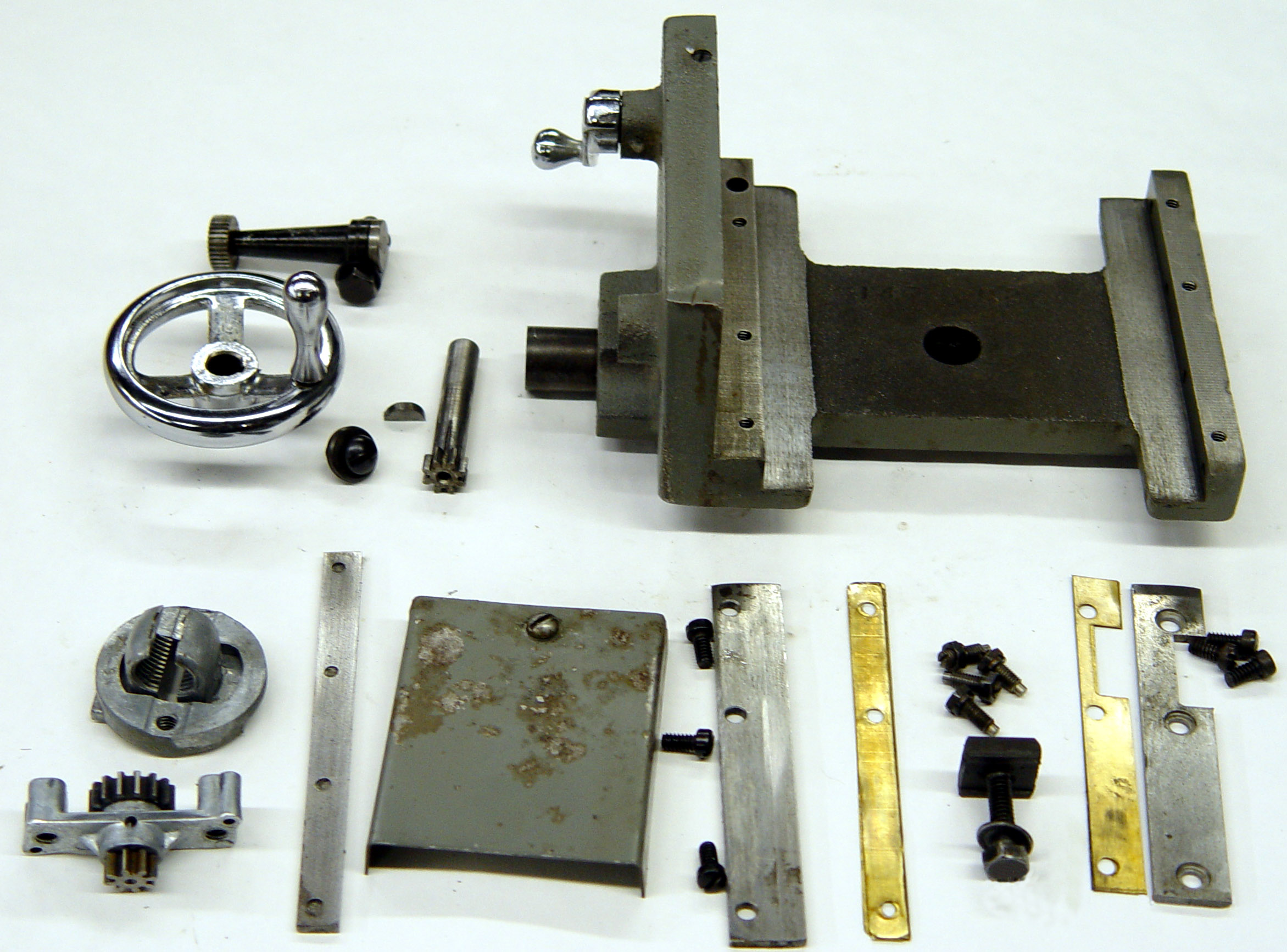
A simple but adequate single-sided apron with proper twin clasp nuts and a "geared-down" drive from the handwheel to the leadscrew was used and remained unchanged for the life of the machine. Like that used on its larger brother the cross slide was of the "short" type that tended to wear the ways in their middle section; it carried a sheet metal cover at the rear to protect the feed screw. The top slide could be rotated through 360º and, happily,  was T-slotted - so easing the fitment of alternative toolposts to the simple and traditional single holder fitted as standard. Unfortunately, both feed screw micrometer dials and handles were tiny - though by way of compensation all the carriage hand controls, even the leadscrew clasp-nut handle, were chrome plated.


Carriage assembly Atlas 6-inch Mk. 2 with chrome-plated handwheels

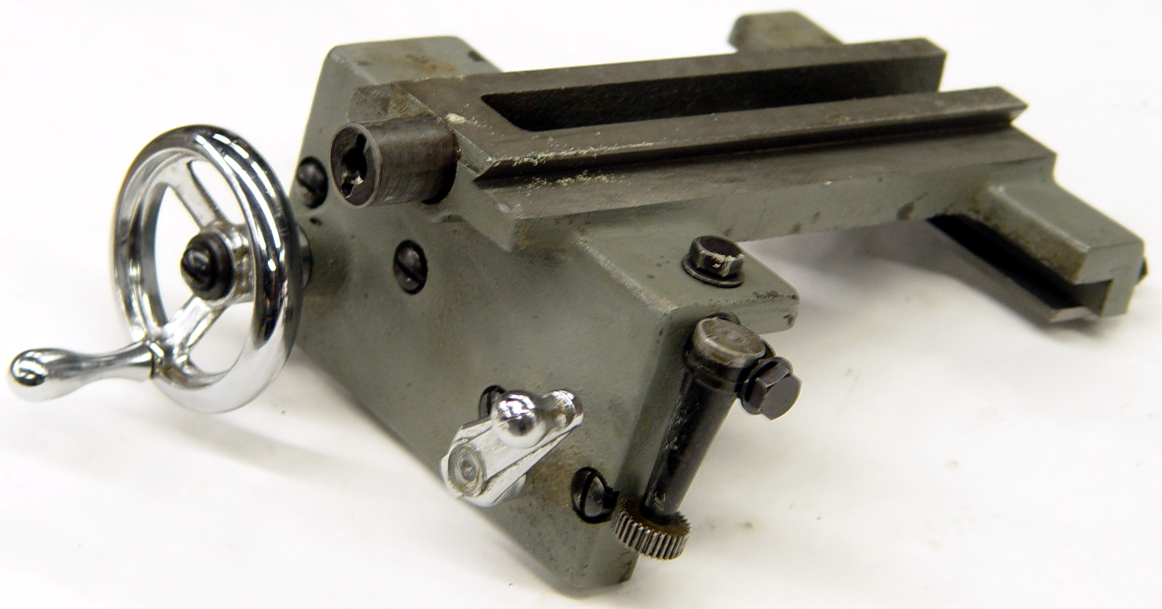
Carriage assembly Atlas 6-inch Mk. 2. The small micrometer dial allowed the cross slide to pass over the top of it. Unfortunately the gib strips were made of hard plastic and the whole of the compound assembly is improved by replacing them with ones in steel.


Rear of the compound slide showing evidence of cost cutting: the cross slide was of the "short" type - which wore just the central portion of its ways - and an adjustable gib strip was fitted at the back of the saddle. This had become an old-fashioned method of adjusting the saddle to the bed in the 1920s and, although more complicated to engineer, the strip should have been placed at the front, so leaving a "solid" rear face to take cutting thrust directly against the bed.

Early saddle and apron assembly

Saddle and apron cast as-one


Atlas 6-inch Mk.2 continued here

An Operation Manual and Parts List is available for
the Atlas 6-inch Mk. 2 lathe


Atlas Mk.1 6-inch Home    Atlas Mk.1 6-inch Page 3

Atlas Mk. 1 6-inch Page 2   

Atlas 6-inch Lathe Accessories   Atlas Mk. 2 6-inch

   Atlas 6-inch Mk. 2   Atlas Home Page  Atlas 6-inch Mk. 1 Photographs

Atlas 9, 10 & 12-inch Lathes   Atlas Milling Machine   Atlas Shaper

Atlas 6-inch with Screwcutting Gearbox   A Restored Model 612

Atlas 6-inch Lathe Mk. 2
email: tony@lathes.co.uk
Home   Machine Tool Archive   Machine-tools Sale & Wanted
Machine Tool Manuals   Catalogues   Belts   Books  Accessories