Screwcutting Lathe Model 00 "> Ames of Chicopee Lathe

E-MAIL   Tony@lathes.co.uk
Home   Machine Tool Archive   Machine-tools for Sale & Wanted
Machine Tool Manuals   Machine Tool Catalogues   Belts   Books   Accessories

Ames of Chicopee Mass.
Precision 71/4" Backgeared and
Screwcutting Lathe Model 00

If any reader has an Ames lathe, and would like to supply a set of
pictures for use in the Archive, the writer would be delighted to make contact

Chicopee Page 2   Page 3 - Chicopee Parts Pictures   Chicopee Page 4

The "other" Ames Home Page

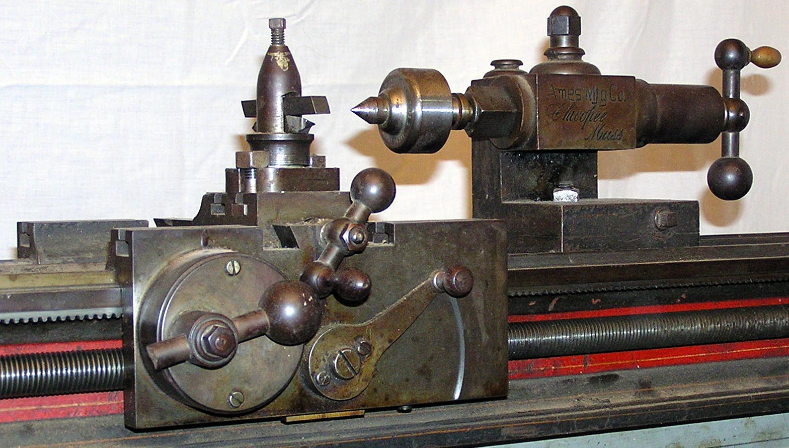
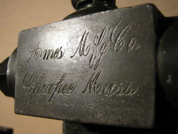
A different company to that founded by Bliss Charles Ames on Ash Street in Waltham, Ma. in the late 1890s, the Ames Mfg Co Chicopee, were known during the 1800s as a maker of swords and other weapons. Although little is known of Ames Chicopee machine-tool production, they must have been at the forefront of developments: an example of their gunstock copying lathe is in the London Science Museum and several versions of an early and beautifully-made 7.25" swing backgeared and screwcutting lathe have survived. Although dating the lathes shown here must be a matter for conjecture, with Ames Chicopee founded in 1810 and machine-tool production starting in 1835, they could have been made at any point from the latter date onwards. One wonders if the Ames Chicopee design had any influence upon the precision plain-turning bench lathe made by Stark in 1862 - a machine that enabled America to take the lead in the manufacture of such machines and as exemplified by Levin, Bottum, The American Watch Tool Company, B.C.Ames, Bottum, Hjorth, Potter, Pratt & Whitney, Rivett, Wade, Waltham Machine Works, WadePratt & Whitney, Rivett, Cataract, Hardinge, Elgin, Remington, Sloan & Chace, and (though now very rare) Frederick Pearce, Ballou & Whitcombe, , Sawyer Watch Tool Co., Engineering Appliances and Fenn-Sadler the "Cosa Corporation of New York" and UND.
Although at a glance very similar, each Ames Chicopee lathe so far discovered has a number of significant differences, thus proving that a programme of steady development must have been in place and hance a reasonable number sold. Several design features and details stand out, some of which reflect contemporary practice while others show unexpected diversions from it (though of course, the features listed might not ally to all examples found). Interesting example include all the major castings in a fine-grain material with the "appearance" of being solid steel; a headstock with narrow, un-braced bearing posts (common at the time) secured not by studs and nuts but screws with thick, slotted heads, a fine thread and set in counter-bored holes; adjustable bronze spindle bearings; nuts were all of the more costly flanged type and obviously all fasteners were made by the lathe maker - there being no known standard and, in any case, most with different thread diameters and pitches - though the most common appears to have been 1/4" x 20 t.p.i.. To ensure nothing was mixed up, where an assembly used more than one fastening, the head of the screw and its location were stamped with a corresponding number - an essential if labour-intensive activity. One example of a non-standard fastening was the bolt used to secure the tailstock to the bed; this appeared, upon initial inspection, to be 1/2" x 20 t.p.i. but, turned out to be 0.470" x 20 t.p.i. - might this have been intended as 15/32"? The full and varied list of fastening on one lathe comprises: 3/16" x  26 t.p.i.; ¼" x 24 t.p.i.;  5/16" x 20 t.p.i.; 3/8" x 20 t.p.i.;  25/64" x 18 t.p.i. (nuts that hold the changewheels in place); 7/16" x 18 t.p.i.; 15/32" x 20 t.p.i.; 13/16" x 12 t.p.i. spindle nose and 0.391" x 12 t.p.i. Square-form thread on the cross-slide and tailstock feed screws. Another area of hand fitting and assembly involves the tumble-reverse gears, these and their mounting studs all being number stamped with the flanged securing nuts being supplied in three different sizes - none of which have any form of modern thread.
Other features included an unusually wide, beam-type gapless bed with ways that ran past the front and back faces of the headstock so allowing the carriage (with its long, equally proportioned wings) to bring the cutting tool up to the spindle nose; a carriage traverse handwheel mounted on a large-diameter round boss that contained a set of reduction gears inside that engaged the bed-mounted rack to give a fine and steady feed to the hand feed (a system that was very unusual at the time when a quick-action, awkward-to-use crank handle would have been expected). The cover, instead of being a simple, prosaic affair was made from a casting of the very finest grain and appeared to have been either gun blued or treated to some contemporary but now unknown "slow-to-rust" finish.
Instead of a full compound slide-rest assembly with both a cross and top slide, all versions of the lathe (common at the time) had just a cross slide with the original toolpost appearing to have been one with a screw-feed height adjustment.
Continued below:

The expensive helical backgears would suggest that this is an earlier version of the lathe,
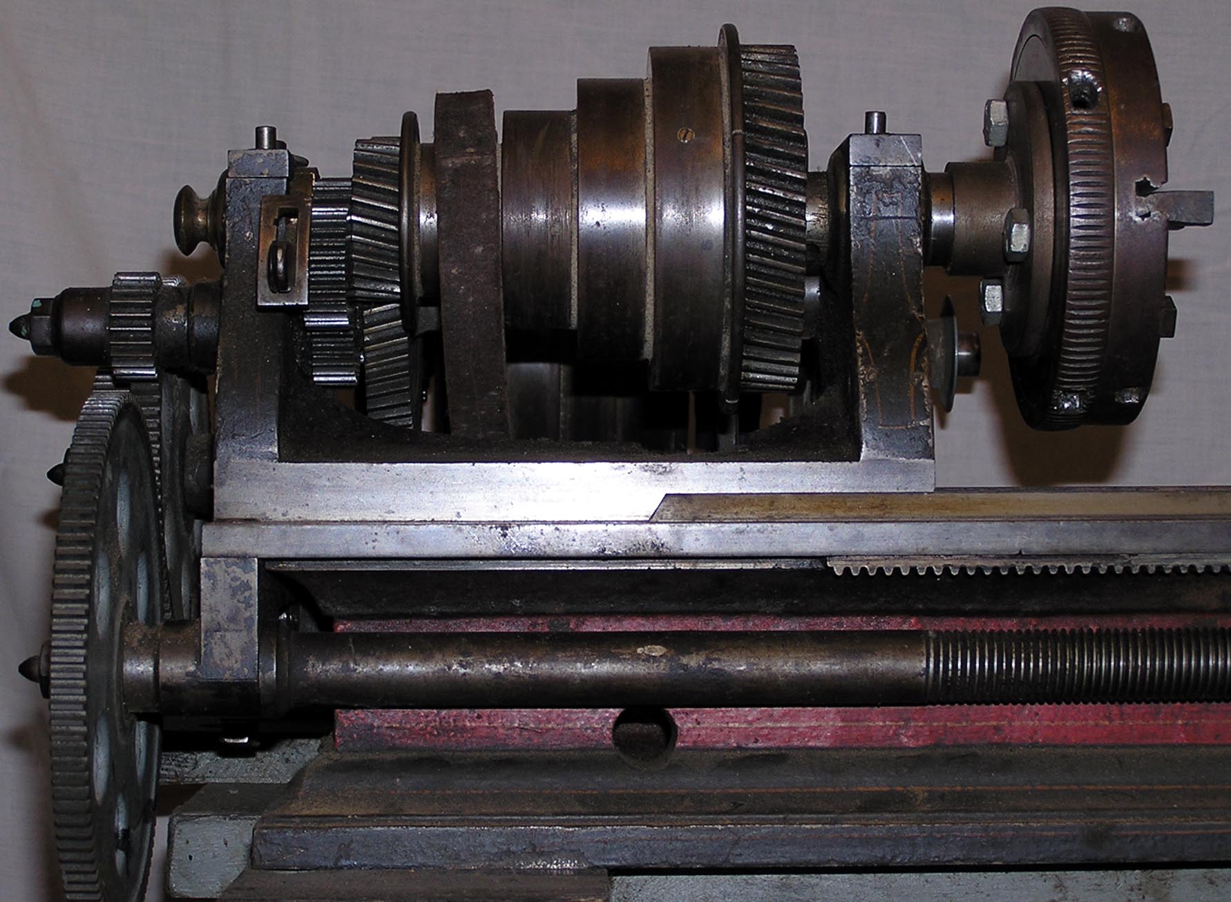
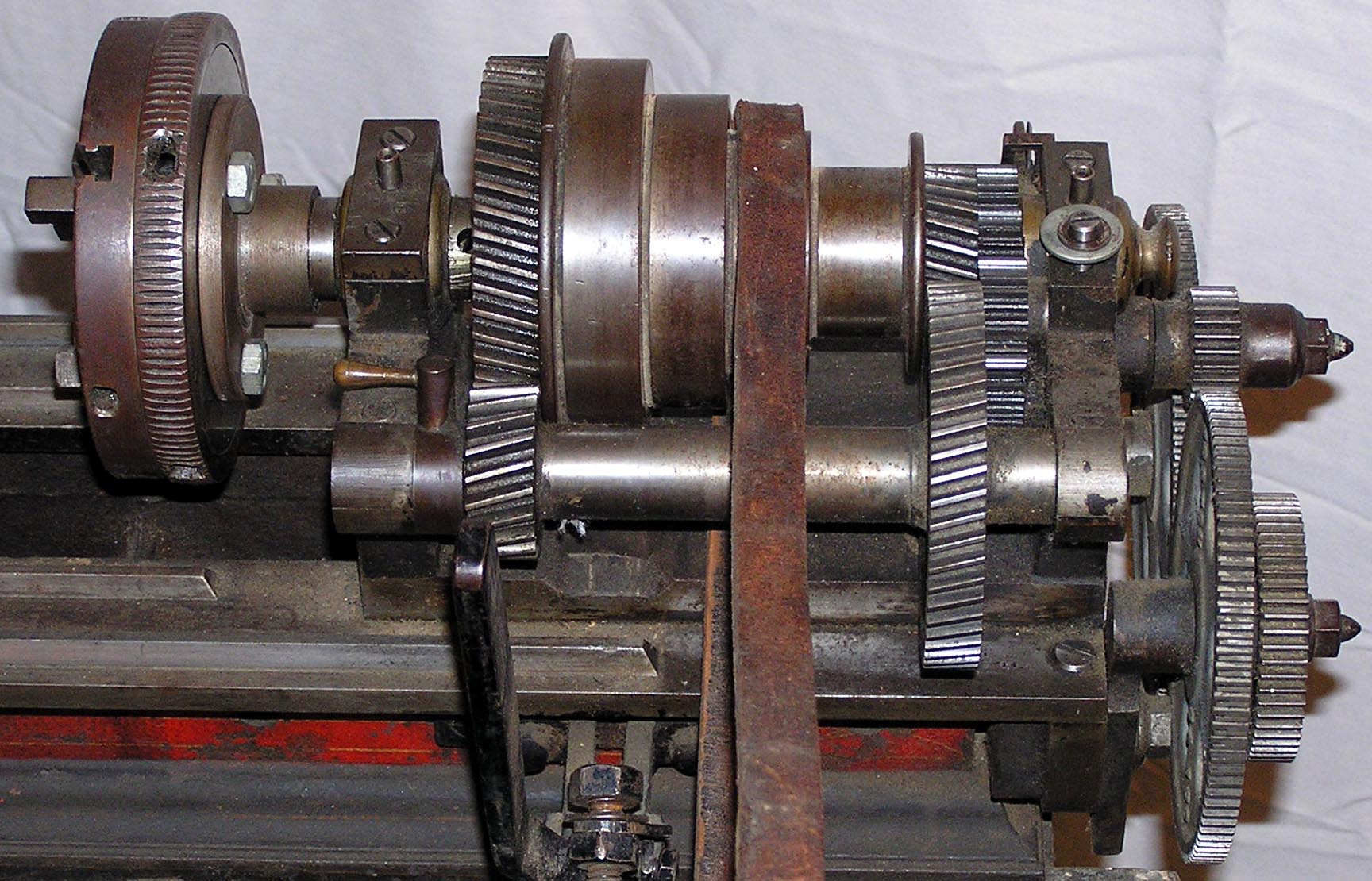
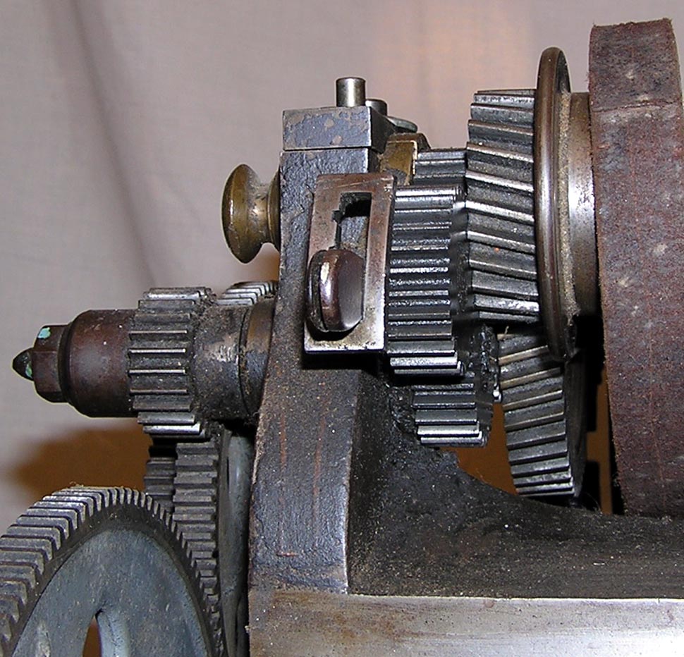
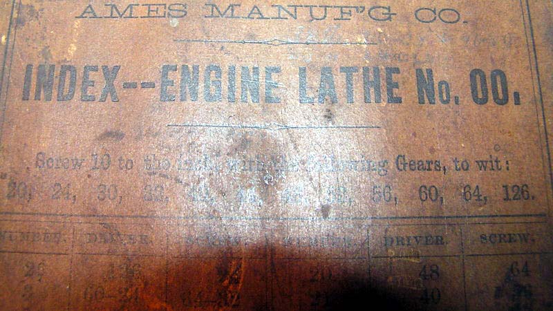
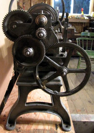
the newer machines having the same gears made with very coarse-pitch spur teeth.

Continued:
On the underside of the bed are clear tool marks from the use of a planer and, under the saddle, similar but finer marks suggesting that a group of these casting would have been "ganged" to be machined at one go. At the front of the apron - and in line with the rack - is a small saddle "keeper plate", the fit of this being adjustable by a small screw to set the clearance to the narrow (just 3/32" wide) underside way. On other parts of the lathe there evidence that rotary cutters were used, though what form these might have taken is uncertain.
Astonishingly, the rack against which the rack-pinion gear engaged was not bolted to the bed, it was part of it; quite why the makers went to the considerable throuble of machining a rack into the bed casting is almost beyond understanding.
Of a fine pitch (a very coarse thread being more usual at the time) the leadscrew was obviously intended to generate a very wide range of pitches, rather than to just provide a sliding power feed. The leadscrew clasp nuts were beautifully made in bronze and, on the example dismantled, show almost no signs of wear. To adjust out end float in the leadscrew - while also providing a form of thrust bearing - the tailstock end-support bracket held a hard leather washer against which the leadscrew pushed - the same system, but using a red fibre material, being employed on some Dalton lathes
An examination of the original finish of the apron's front face (preserved beneath the handwheel boss) shows it to have been highly polished by what must have been laborious hand work.
Changewheels were, like the rest of the lathe, given a superb cosmetic finish being fully machined on both faces and retained by elegant hand-knobs. However, of the surviving lathes, three have sets of new Boston gears with them and only one the originals - which appear, on inspectionl to be of a unique tooth form.
On one example of the lathe (with spur-gear backgears), as originally manufactured there was no tumble reverse - nor any other method of reversing the direction of the leadscrew - and hence would have been restricted to cutting just right-handed pitches. However, others examples do have tumble reverse - with one having the indent arm fastened to the inside face of the headstock casting while another has it secured by a single, slotted-head screw against a slot cut neatly into the front face below the left-hand headstock bearing. On the earlier of the two models, the one with helical backgears, the tailstock spindle is square; a tricky job to machine and fit to perfection.
From the remains of the original finish on the older example (unfortunately the newer  appears to have been polished) the maker's paint (heavily oxidised of course) would seem to have been a darker grey/green on the major castings with a red band along the front of the bed and adornment by the usual Victorian-style of lining-out in red and gold. A later version of this lathe, a reflection of contemporary practice, can be seen here.
An example of the Chicopee is currently (December 2018 into 2019) undergoing a sympathetic restoration by a leading USA antique machine-tool specialist and he reports, that, so far, the quality of construction discovered is of the highest standard and well beyond what he was expecting. It appears certain that Chicopee, being used to making military hardware, had carried over the skills of its workforce into the machine-tool world. Happily, the lathe shows hardly any sign of wear and hence it has been possible to judge the tolerances and limits likely to have been used during its construction - all of which appear to have been remarkably fine and consistent. Examination of the headstock has revealed a spindle with a 13/16" x 12 t.p.i. thread and a No. 1 Morse taper socket and a backgear shaft with 0.001" of clearance - a similar level of accuracy being found in the main spindle-to-cone pulley fitting. Strangely, for its age, it appears that the spindle journal bearings, backgear shaft and main spindle were all finish ground. At the time the use of cylindrical grinders for precision finishing of parts was few and far between for, although the first cylindrical grinder (for finishing parts of the Willcox & Gibbs sewing machines) had been made in the 1830s, subsequent developments in this field did not take place until the period 1860 to 1876.
Heat-treated, the cross-feed and tailstock screws were well made, each with a 0.39" diameter, square-form thread of 12 t.p.i. pitch.
Careful work - it involved removing a bracket fitted long ago -  has revealed a rather fine medium blue paint with bright red pinstriping - though this differs from that on the first lathe below in being of a plainer pattern - but obviously original.
Bearing mind the quality of construction, the fine cosmetic finish and attention to detail (even small casting flaws in the back of the carriage handwheel were filled with bronze inserts), this Ames Chicopee lathe must have been, when new, a very expensive proposition indeed..

There is every chance that this lathe retains its original dark green finish with a  band of
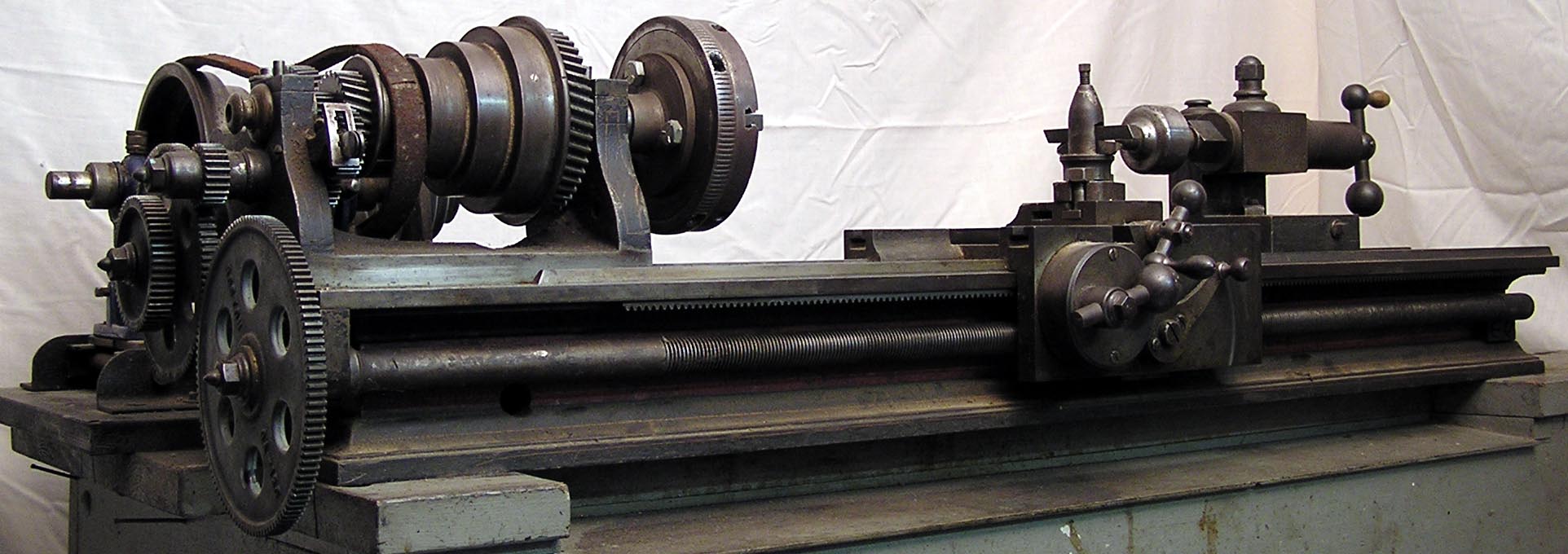
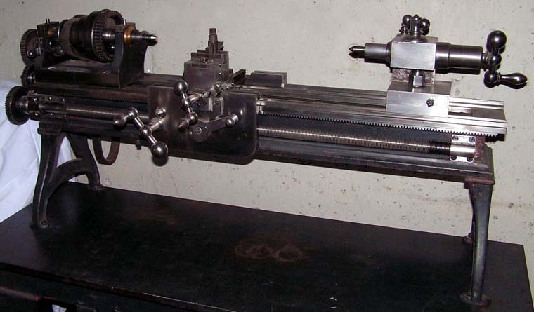
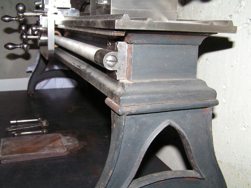
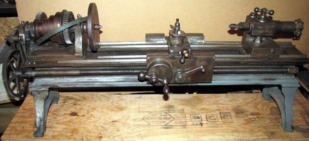
red down the face of the bed and adornment by the usual Victorian-style lining out

This example of an Ames Mfg Co Chicopee lathe has factory-fitted tumble reverse mechanism fitted to the changewheel drive

Note the fine-pitch leadscrew; this lathe was obviously intended for the generation of threads and not just to have a powered sliding feed

The carriage traverse handwheel engaged the bed-mounted rack through a system of reduction gearing - a most
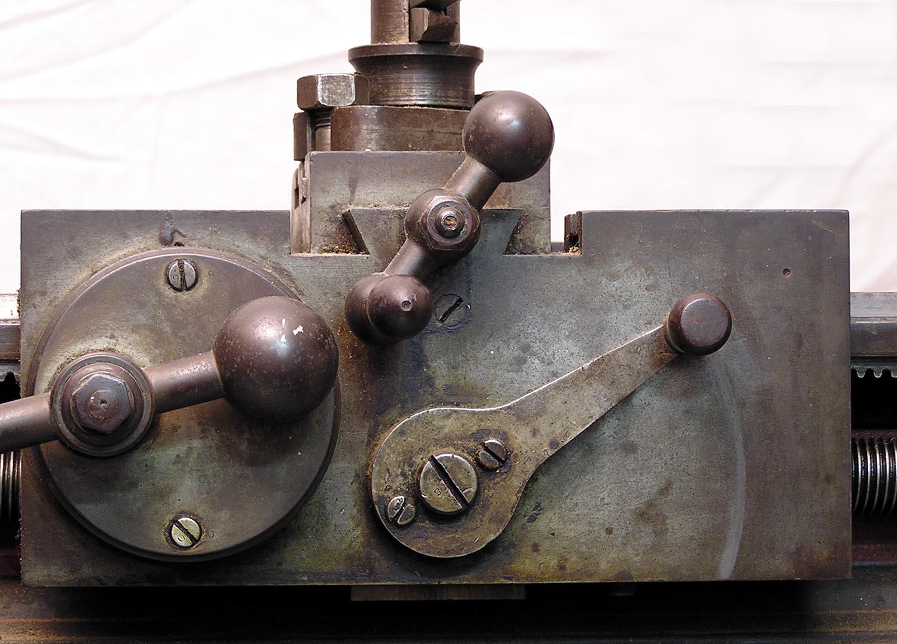
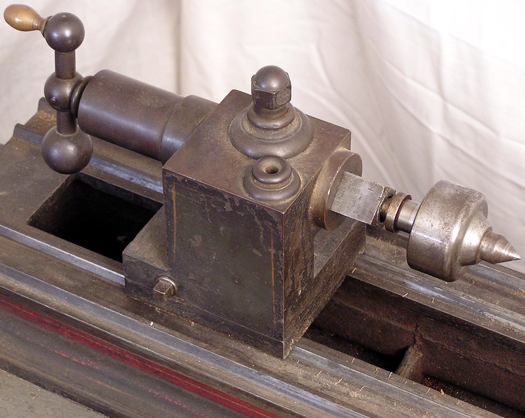
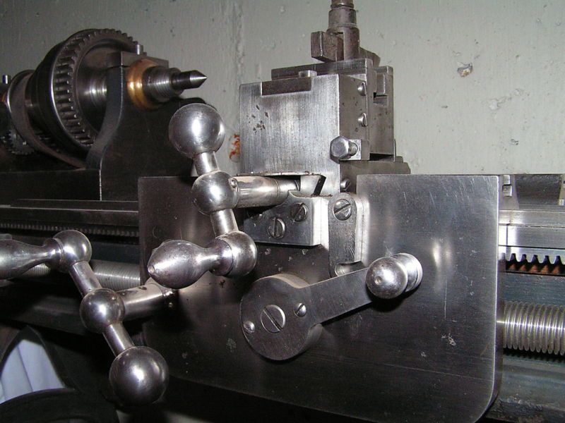
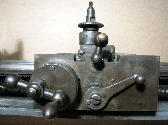
unusual system on this age of lathe where a quick-action crank handle would have been the expected fitting

On the earlier of the two models, the one with helical backgears, the tailstock spindle is square; a tricky job to machine and fit to perfection.

Backgears on the early versions were an especially coarse-pitch spur type.
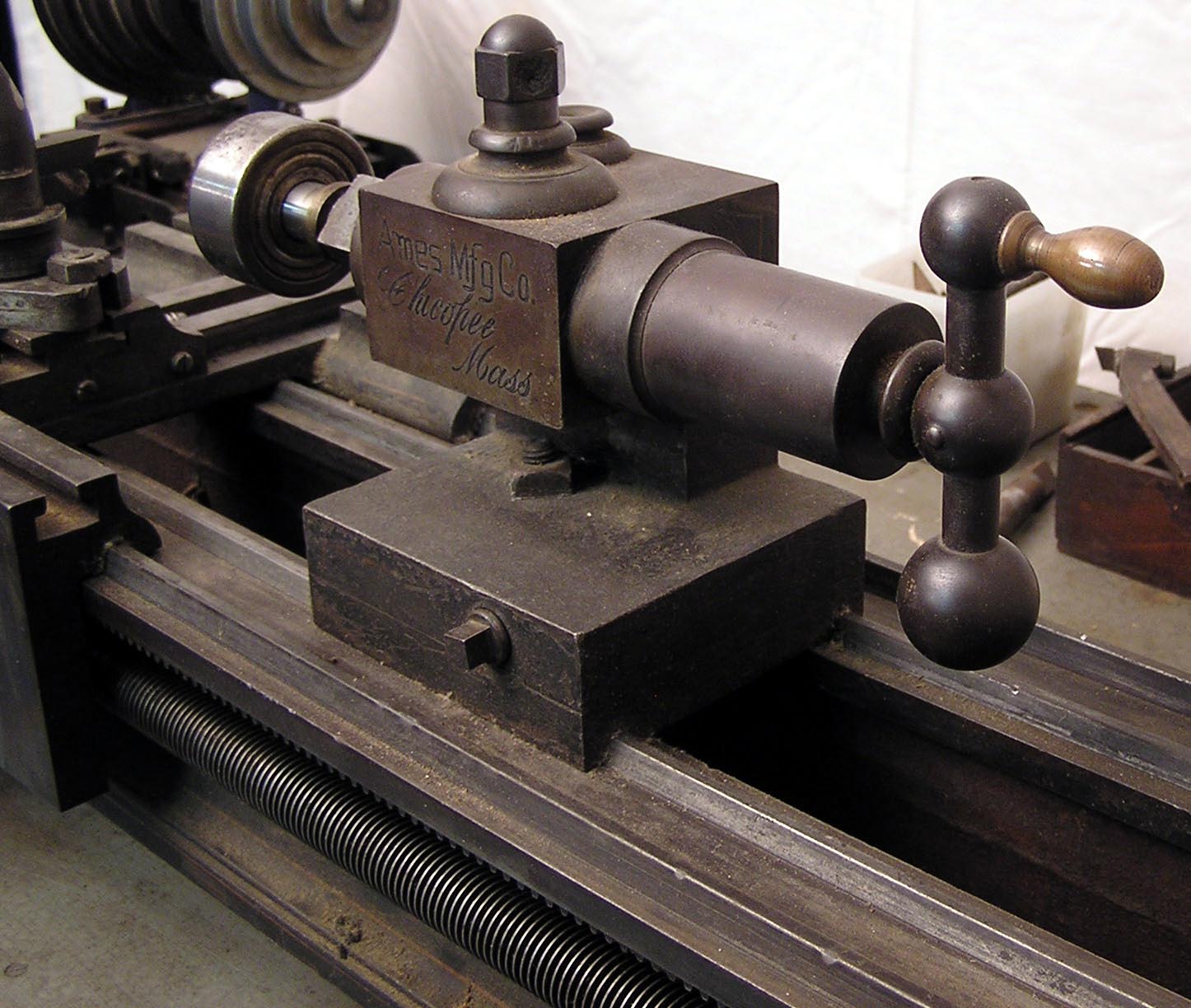
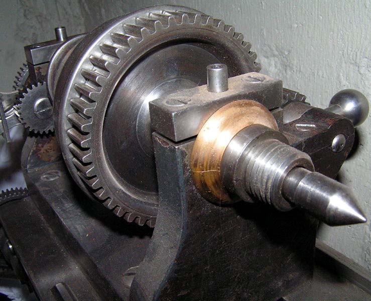
Note the use of slot-headed screws to secure the headstock

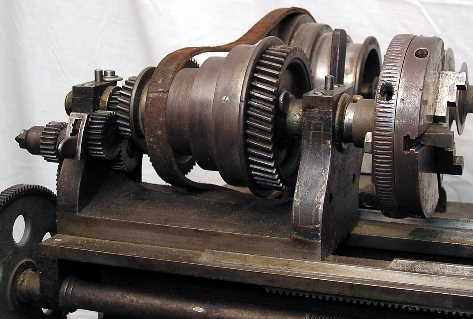
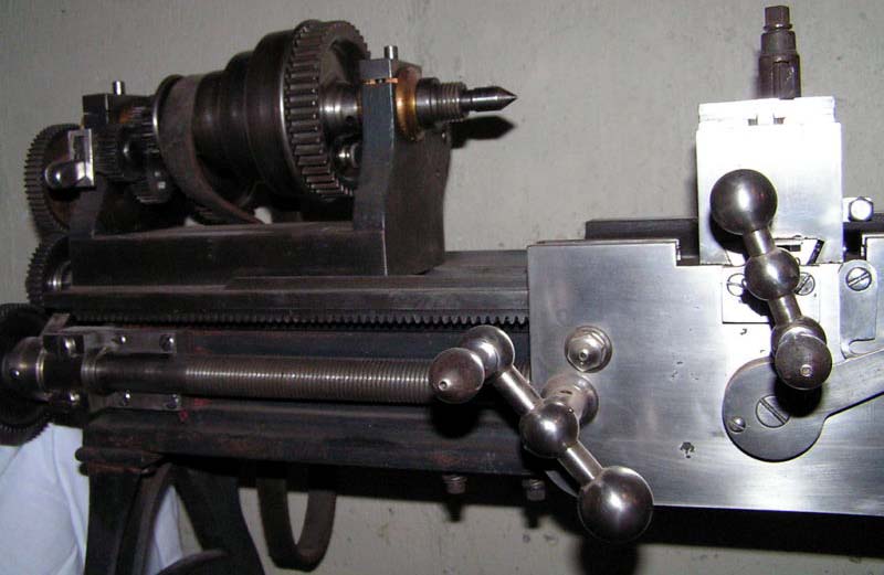
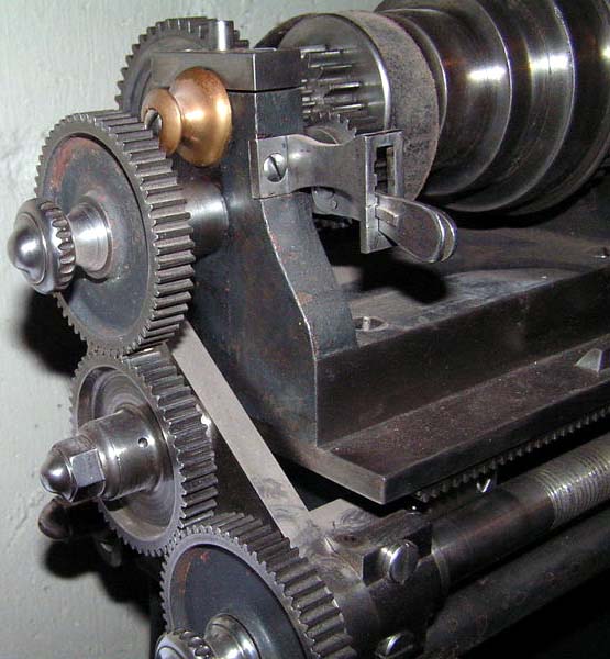
A different arrangement of the tumble-reverse mechanism - clearly original as the individual parts mirror those on lathes with the indent arm carried on the inside face of the headstock. Elegant, notched-edge handscrews retained the changewheels

The later of the two examples has a conventional cylindrical tailstock spindle. Note the beautifully formed locking handle

An exceptionally wide bed with V and flat ways arranged separately for carriage and tailstock

Above and below: even the original screwcutting charts have survived

A third example of an Ames of Chicopee Mass. lathe

Chicopee Page 2   Page 3 - Chicopee Parts Pictures   Chicopee Page 4

The "other" Ames

Ames of Chicopee Mass.
Precision 71/4" Backgeared and
Screwcutting Lathe Model 00

If any reader has an Ames lathe, and would like to supply a set of
pictures for use in the Archive, the writer would be delighted to make contact

E-MAIL   Tony@lathes.co.uk
Home   Machine Tool Archive   Machine-tools for Sale & Wanted
Machine Tool Manuals   Machine Tool Catalogues   Belts   Books   Accessories