 |
|
|
|
|
|
|
|
|
|
|
|
|
|
|
|
|
|
|
|
|
|
|
|
|
|
|
|
|
|
|
|
|
|
|
|
|
|
|
|
|
|
|
|
email: tony@lathes.co.uk
Home Machine Tool Archive Machine-tools Sale & Wanted
Machine Tool Manuals Catalogues Belts Books Accessories
Advance Lathe
Advance Lathe Continued Here Rebuilding an Advance Lathe
Other Australian-built lathes include: Bourke, Brackenbury & Austin, Clisby
Burden, Great Scot & Conrik, Hercus, Herbert, HTC, Premo, Qualos, Macson,
Mars, Nuttall, Parkanson, Purcell, Rexman, Rolfe, Sheraton, Tillico, T.N.C. & Veem
If you have a Mk. 2 Advance the writer
would be delighted to have photographs for display
|
|
|
|
|
|
|
|
|
|
|
|
|
|
|
|
|
|
|
|
|
|
|
|
|
|
|
|
|
|
|
|
|
|
|
|
|
|
|
|
|
|
|
|
|
|
|
|
|
|
First produced in Australia during the lathe 1940s, the Advance lathe was manufactured by Bert Kirby in Mount Alexander Road, Mooney Ponds, Melbourne. After the Mr Kirby's in the early 1960s the rights to his lathe were bought by Alfred Stewart Pty Ltd. a tool merchant and tool manufacturer - they produced engineers' hand tools from a factory in North Melbourn - who traded, until about 1975, from 391 Little Bourke Street, Melbourne. Despite the simple arrangements that such a transfer would seem to imply some lathes are marked "Alfred Stewart Pty. Ltd. Melbourne, Aust. Sole Agents for Advance Machine Tools Pty. Ltd." while others carry the legend: "Alfred Stewart Manufacturing Engineers Pty. Ltd Kilsyth Victoria". After Alfred Stewart Industries (who marketed Myford lathes), production was continued from around 1980 by J. & G. Wylie Industries at Moorabbin (Melbourne), a manufacturer of woodworking and lapidary equipment, who introduced an improved model, the Advance Mk. 2 that was badged, appropriately, as the New Advance.
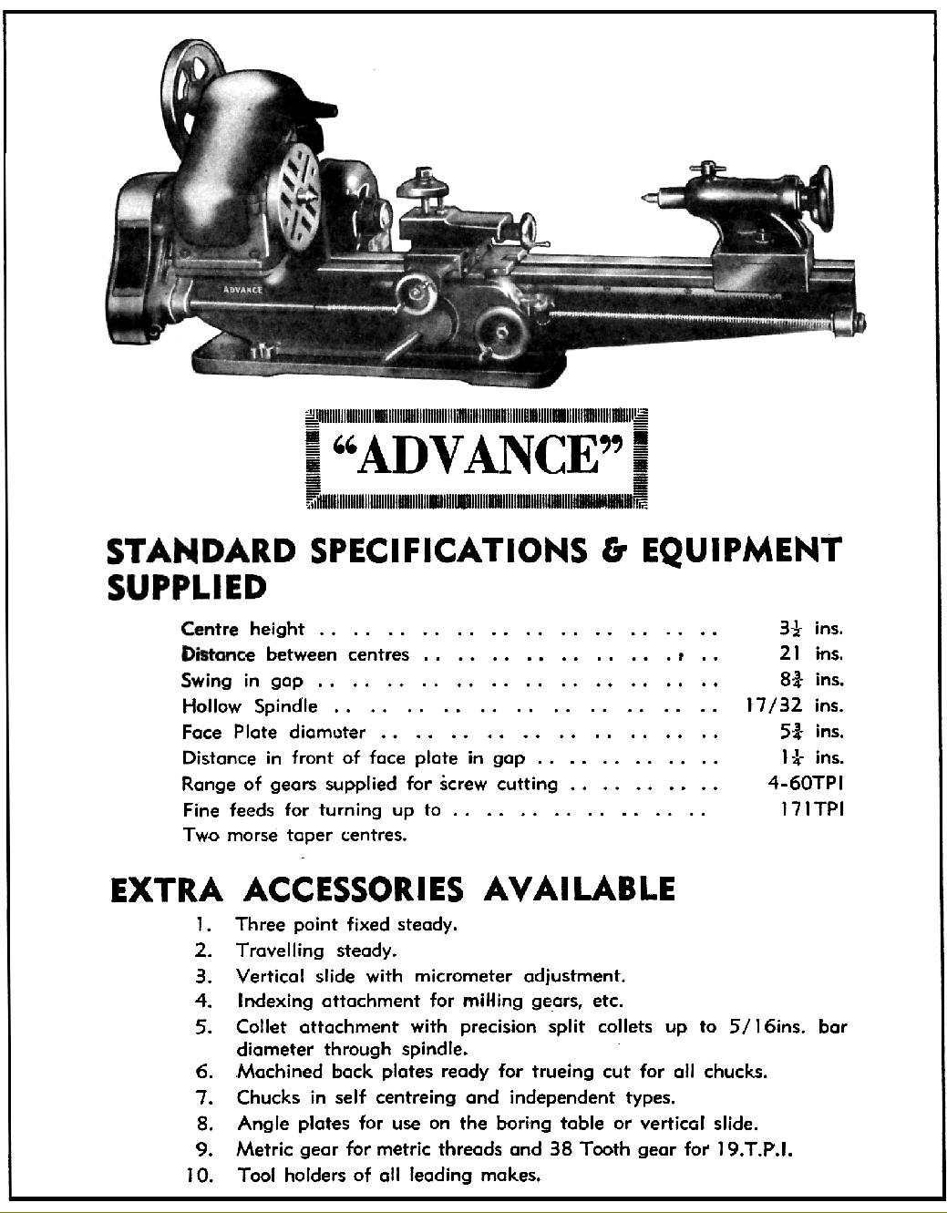
With the first known advertisement of the backgeared and screwcutting model traced to 1947, the Advance was intended to occupy the same market segment as did the contemporary ML7 in the United Kingdom. Well constructed, with no evidence of penny-pinching in its construction, some parts of the Advance, such as the full-circle, beautifully-finished handwheels, were of exceptional quality for its class. Like the contemporary English Perfecto and Swedish VLG, the Advance was based on the design of the pre-WW2 English Myford ML1 to ML4, where the aim was to provide a small, inexpensive lathe that could be adapted to a variety of tasks. The bed, of the cantilever box-form type, was internally ribbed, flat-topped and with 60-degree V-edges. The centre height was 3.5 inches, the capacity in the gap 8.75 inches with the distance between centres being either 12 or, more commonly, 21 inches. Backgear was fitted as standard - arranged exactly like the Myford by being clustered in pairs just inboard of the front spindle bearing with the rear pair mounted on an eccentric shaft. Lathes from the initial batch were rather crude: there was a full nut on the apron (requiring much twiddling of the leadscrew handwheel to move the carriage) and a dog clutch on the leadscrew to allow the screwcutting or carriage sliding feed to be disengaged.
Continued below:
|
|
|
|
|
|
|
|
 |
|
|
|
|
|
|
Continued:
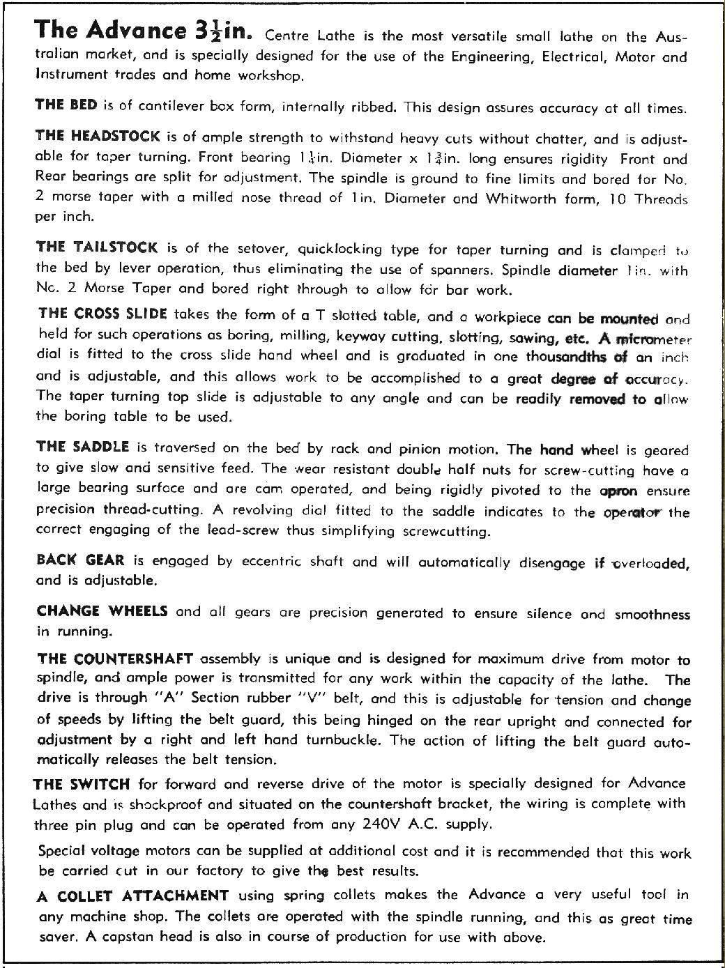
There were no micrometer dials on the feed screws and a very light, upright No. 1 Morse taper tailstock with a limited reach over the cross slide. However, later models were much improved and demonstrated much-improved attention to detail with obvious attempts to overcome the more glaring deficiencies of the original Myford: the base of the headstock was formed into a substantial bracket that allowed it to be bolted down with four studs; the apron was a heavy casting that carried proper leadscrew clasp nuts and a hand-traverse working through reduction gearing for a slower and steadier feed. Both top and cross slides were cast with integral feed-screw support brackets that gave extra travel by allowing the slides to pass well forward over their ways - a very useful T-slotted cross-slide was supplied as part of the ordinary specification. When eventually fitted, the micrometer dial were rather superior - with clear engraving of the divisions, the ability to be zeroed and a narrow band of knurling around the periphery. The tailstock - though it had a rather thin sole plate - was of decent weight and fitted with a simple but effective (and non-distorting side) clamp at the rear. However, the clamp that locked the barrel was that horrible type that should only have been found on the cheapest kind of wood lathe - a directing-acting screw.
Headstock bearings were of the very ordinary split, plain bronze type, closed down by a pinch bolt - that at the front being 1.25-inches in diameter and 1.75-inches long. The 17/32" bore spindle was ground finished, had its 1" x 10 t.p.i. nose thread ground in and carried a No. 2 Morse taper socket. Tumble reverse to the leadscrew drive must have been offered as an extra-cost option on early models (it being seen on some lathes, but not others) though later lists have it listed as part of the standard equipment. Changewheels - 20 D.P. with a 14.5° pressure angle - were provided in a set of (it is believed) 2 x 20t, 25t, 30t, 35t, 40t, 45t, 50t, 55t, 60t, and 70t and were sufficient to generate all common pitches between 4 and 60 t.p.i. (the slowest rate of carriage feed with the standard fine-feed set-up was 0.0058" per revolution of the spindle). At extra cost a 38t gear could be provided for generating 19 t.p.i. as could a composite 20/21t pair intended for metric threading. Drive systems too would have been listed separately, with various kinds of countershafts encountered and fitted in both guarded and unguarded form. However, one fitting does stand out, a neatly built-on unit with a left/right threaded bar to lever the countershaft away from the headstock and so tighten the final-drive belt The outer end of the tensioning bar fitted into a hole drilled into the right-hand face of belt-guard cover with the other end arranged on a pivot that allowed the bar to be swung out of the way. This clever but simple arrangement allowed the belt tension to be slackened immediately and completely and the guard then lifted to change speeds. Equipped with this unit and its standard diameter pulleys, spindle speeds of 900, 600 and 320 r.p.m. in direct drive and 150, 100 and 54 r.p.m. in backgear were available.
A summary of the main developments incorporated over several decades include (in roughly chronological order:
Guard for the cone pulley belt; also formed part of the belt tensioning system.
Tumbler reverse.
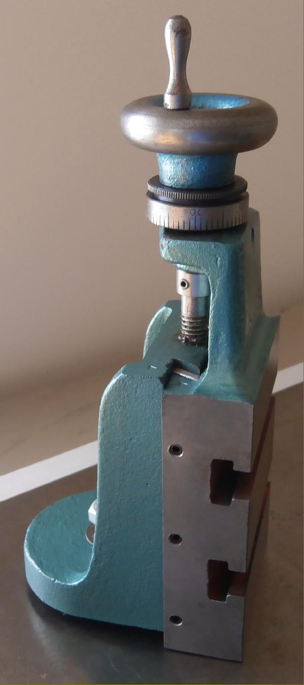
Spigot-type mounting for the top slide, allowing 360 degree rotation.
Micrometer dial on the top slide hand wheel.
A revised bed casting with larger bed ways and heavier ribbing.
Taper roller bearing headstock
Headstock integrally cast with the bed
Spindle nose thread increased to 1.25" diameter
Countershaft and motor unit attached to the back of the bed.
Longer saddle, to accommodate a travelling steady.
Self-ejecting tail stock with clamping of the barrel by closing down a slit in the tail stock casting.
From around 1980, a later model Advance, the Mk. 2, was introduced: this incorporated several improvements including a roller-bearing headstock, a tailstock with its casting cantilevered forwards to improve the reach across the cross-slide, cam-lever locking to the bed and a 1-inch diameter, No. 2 Morse taper barrel and tumble-reverse. While the plain-bearing versions of the lathe had the headstock and bed as separate units the roller-bearings models had a more rigid assembly with the bed and head cast as one (just like the early Myford ML1 and ML2).
Accessories included all the expected items: fixed and travelling steadies, 4-way toolpost, toolholders, Eclipse boring bars, parting tool holders, a small machine vice, collets from 1/16" to 1/12" in 1/16" steps, spare spindle backplates, tailstock chuck, small angl e plate. vertical milling slide, an indexing attachment for gear cutting and a braced sheet-metal cabinet stand.
If you have an Advance, or any advertising or technical literature concerning them, the writer would be delighted to hear from you.. Photographs of the Mk. 2 machine are particularly sought. The story of rebuilding an Advance can be seen here
|
|
|
|
|
|
|
|
|
|
|
|
 |
|
|
|
 |
|
|
|
|
|
|
|
|
|
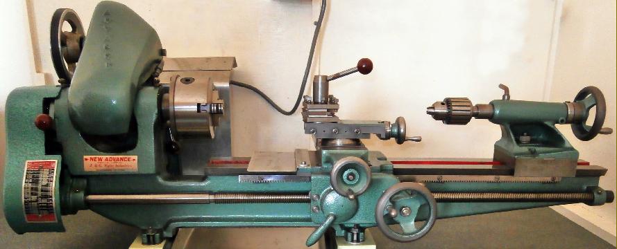
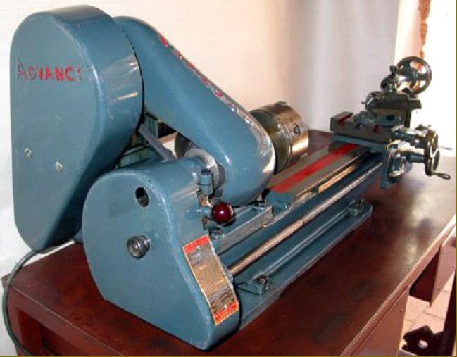
A later Advance showing the some of the interim improvements incorporated: clasp nuts on the apron and rack-feed to the carriage; guards over the belt runs and changewheels and tumble reverse on the leadscrew drive. The No. 2 Morse taper tailstock had its casting cantilevered foreword to improve the barrel's reach across the cross slide.
|
|
|
|
|
|
|
|
|
|
|
 |
|
|
|
|
|
|
From around 1980, a later model Advance, the Mk. 2, was introduced: this incorporated several improvements including a roller-bearing headstock, a tailstock with its casting cantilevered forwards to improve the reach across the cross-slide, cam-lever locking to the bed and a 1-inch diameter, No. 2 Morse taper barrel and tumble-reverse
|
|
|
|
|
|
|
|
|
|
|
|
|
|
 |
|
|
|
|
|
|
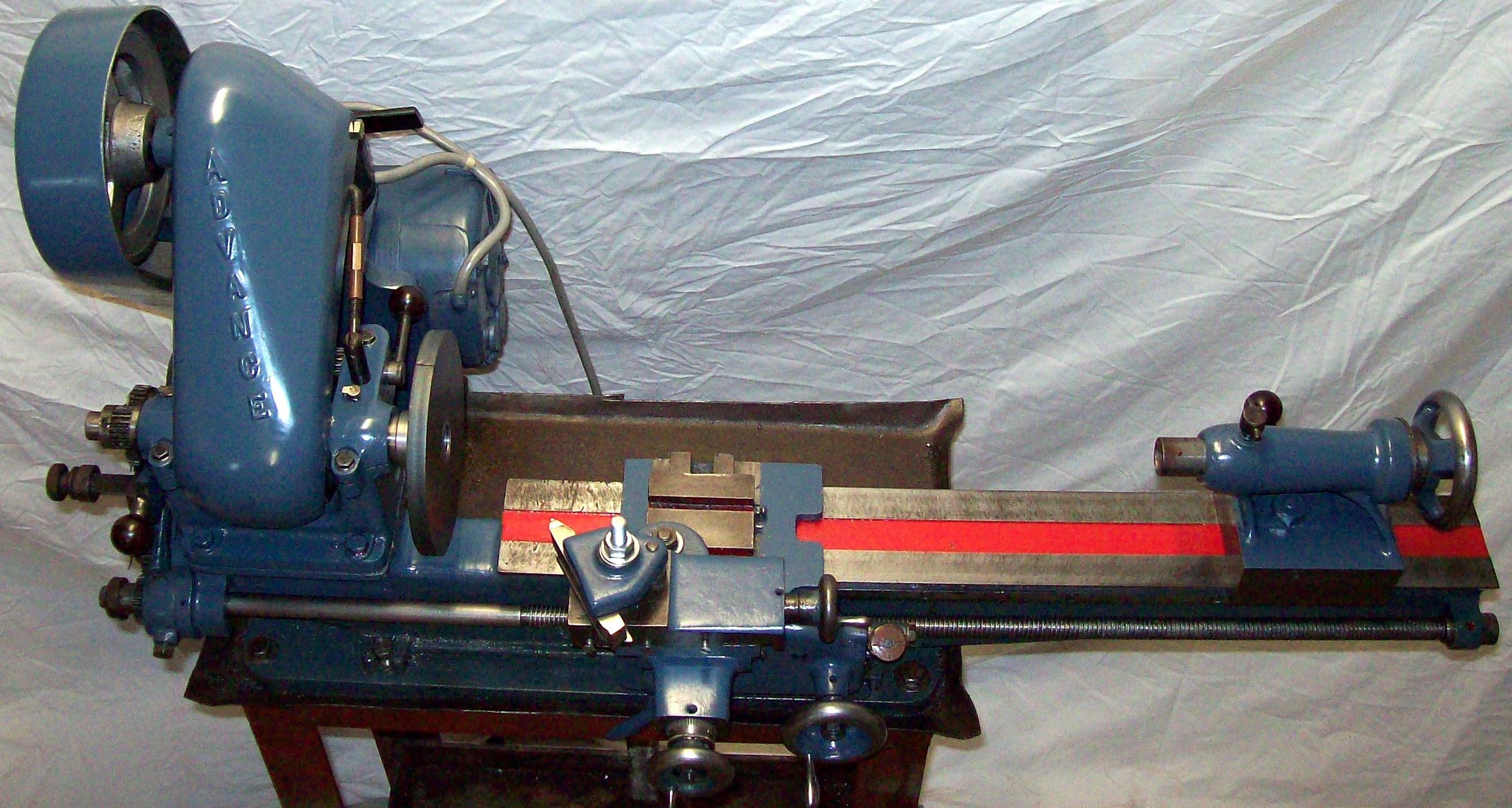
A later Mk. 1 Advance with guarding of the belt runs (the changewheel cover has been removed
|
|
|
|
|
|
|
|
 |
|
|
|
|
|
|
Complete and effective guarding of the belt and gear drives was a feature of later versions of the Advance
|
|
|
|
|
|
|
|
|
|
|
 |
|
|
|
|
|
|
|
|
|
|
|
 |
|
|
|
|
|
 |
|
|
|
|
|
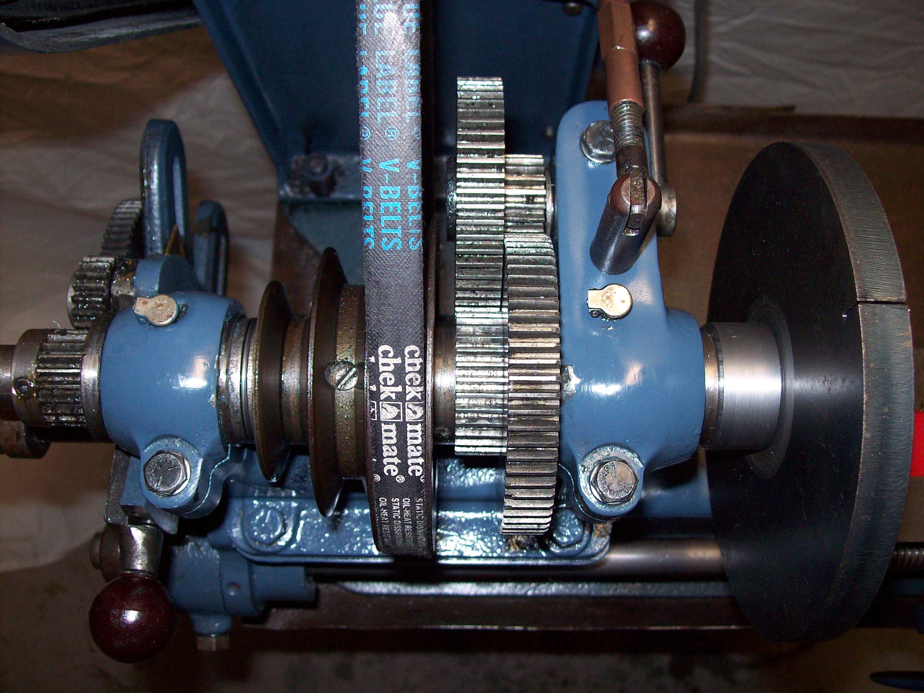
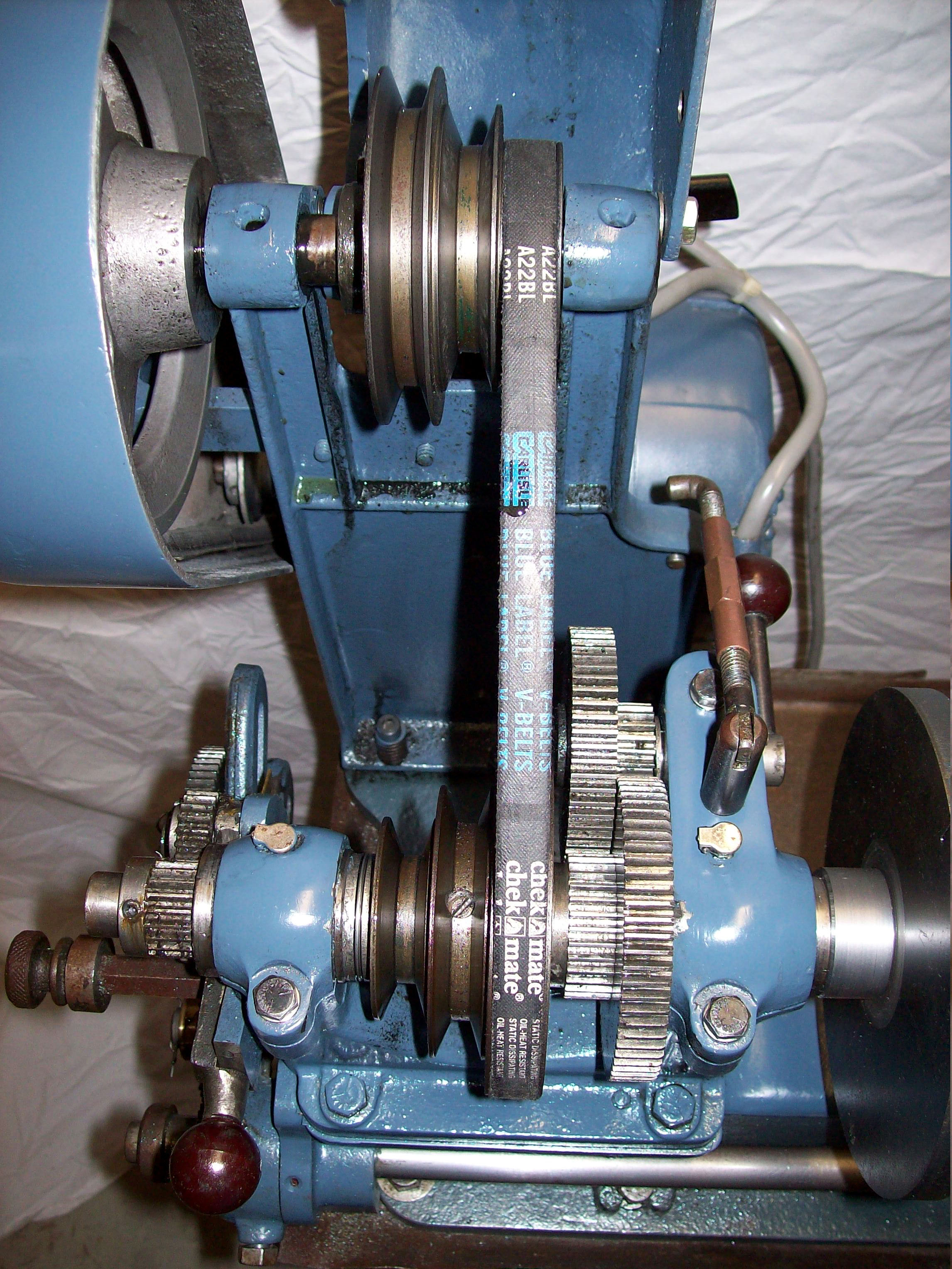
Backgear was fitted as standard and arranged exactly like the pre-WW2 Myford
lathes by being clustered in pairs just inboard of the front spindle bearing
|
|
|
|
|
|
|
|
|
|
|
 |
|
|
|
|
|
|
|
|
|
|
 |
|
|
|
|
|
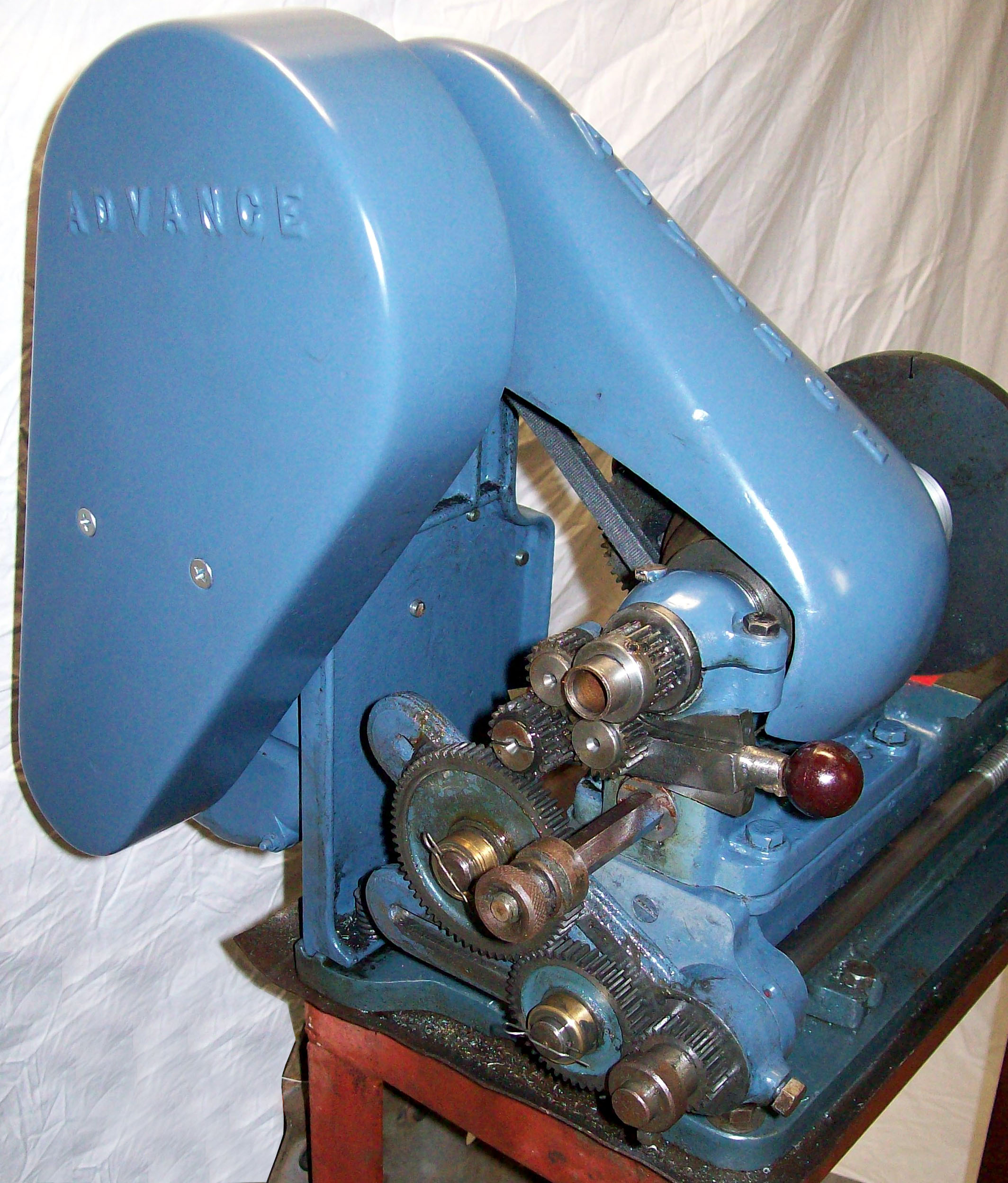
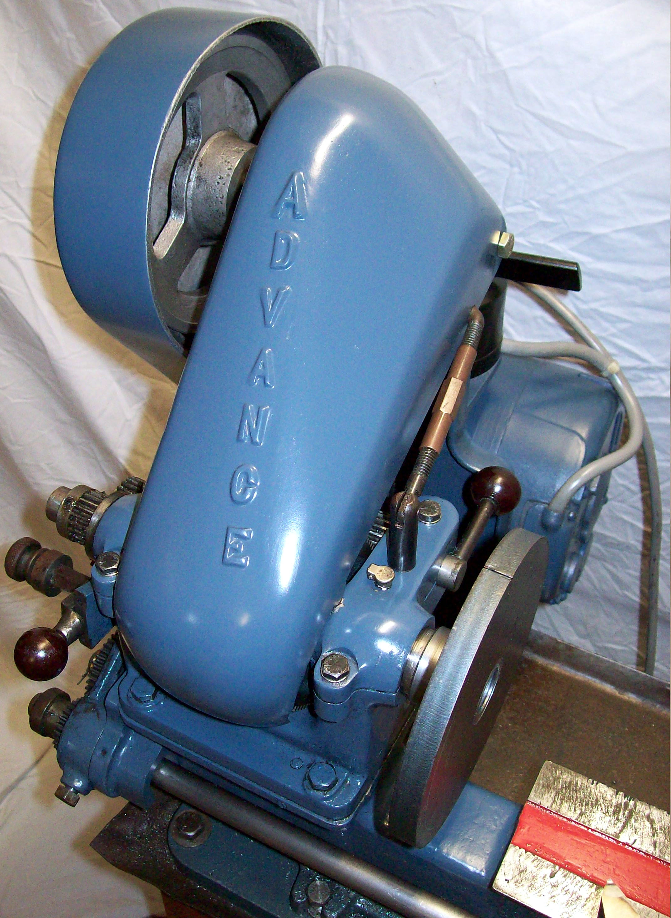
Opening the belt cover automatically released the tension of the headstock spindle drive belt. A long left-handed/right-handed threaded nut was fitted to adjust the final tension
|
|
|
|
|
|
|
|
 |
|
|
|
|
|
Another view of the combined cover/belt mechanism - this time on a roller-bearing headstock Advance Mk. 2, the New Advance
|
|
|
|
|
|
|
|
 |
|
|
|
|
|
|
|
|
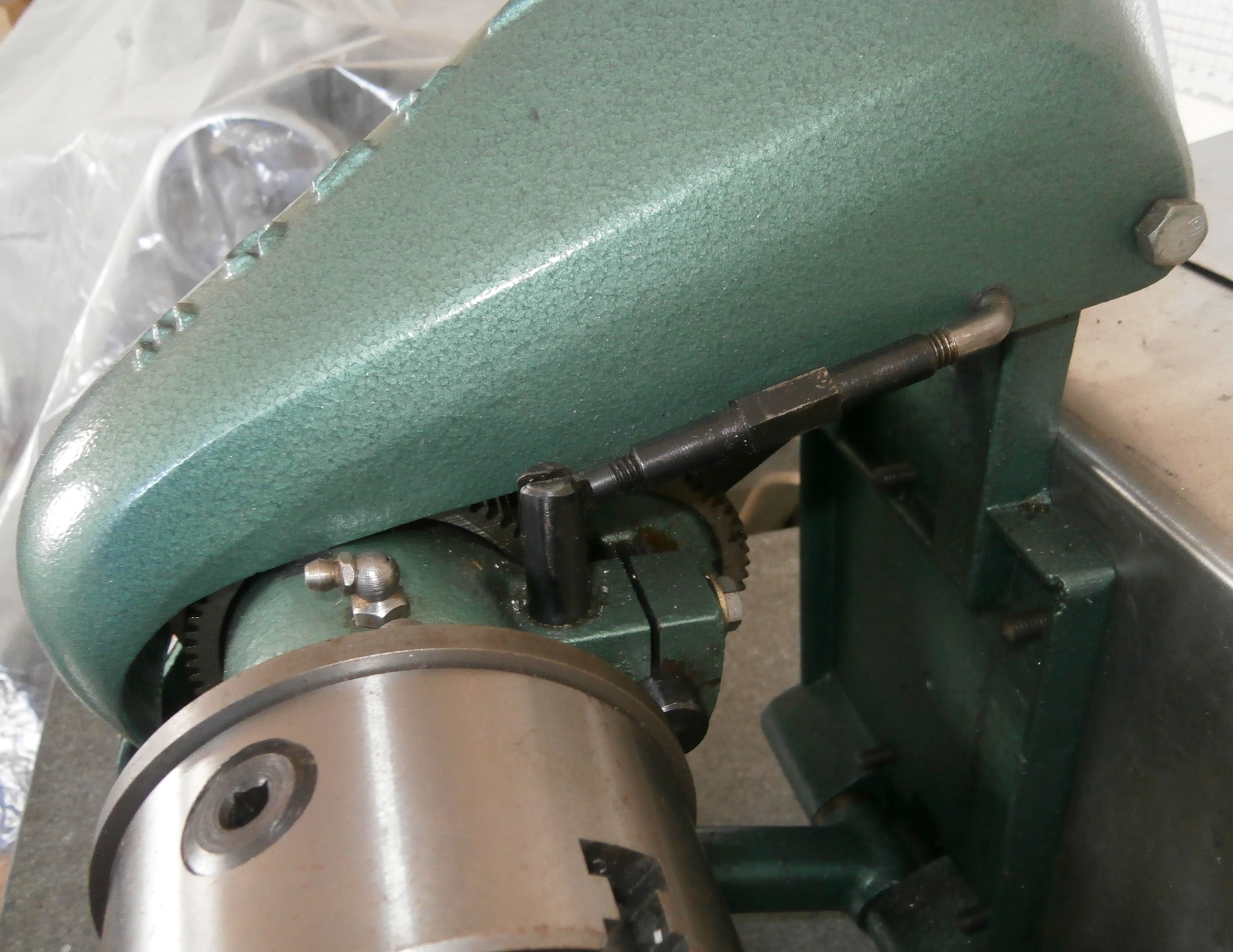
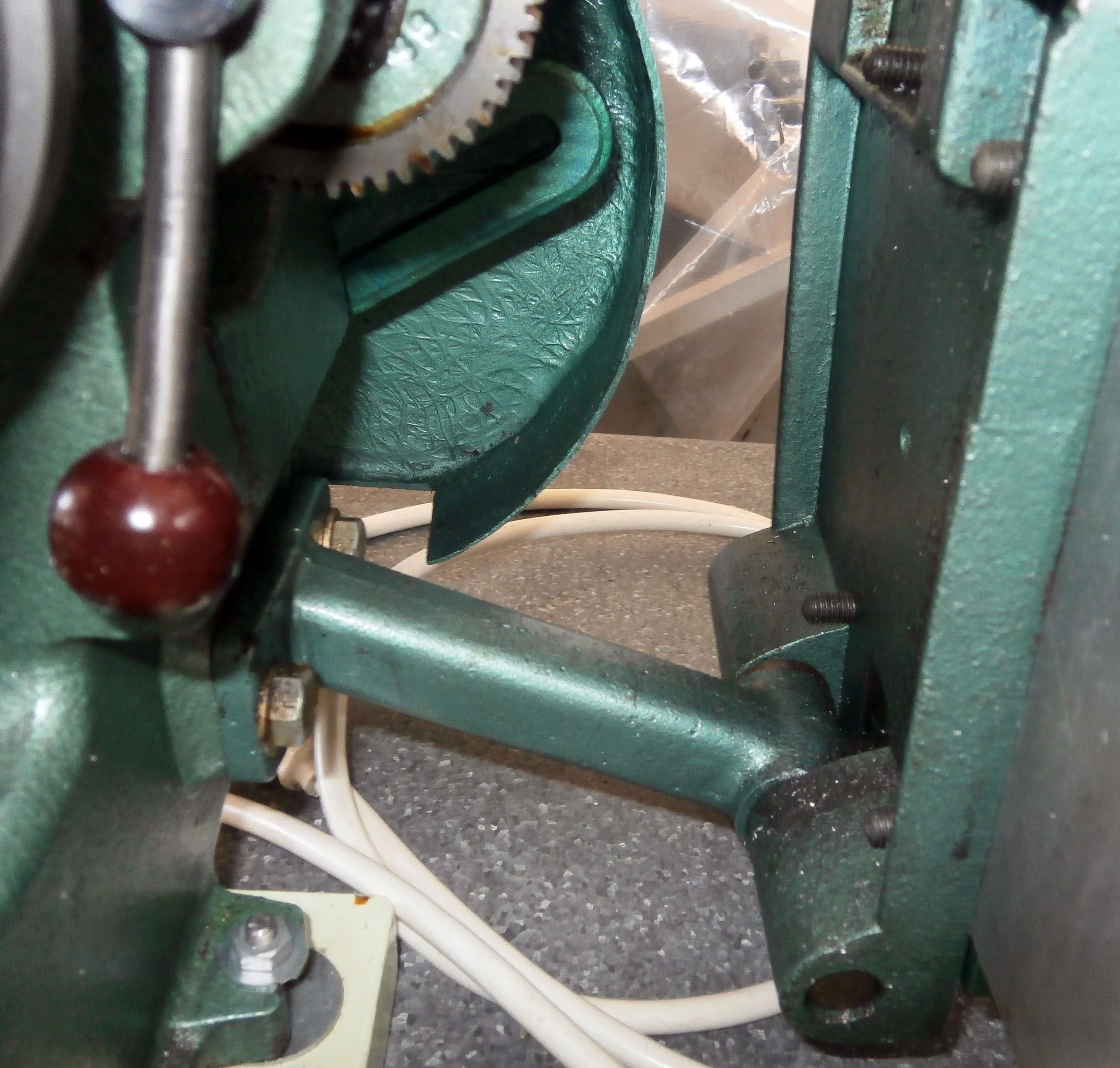
The simple but effective hinge arrangement on the countershaft - the lathe shown is a New Advance model
|
|
|
|
|
|
|
|
|
|
|
|
|
|
|
|
 |
|
|
|
|
|
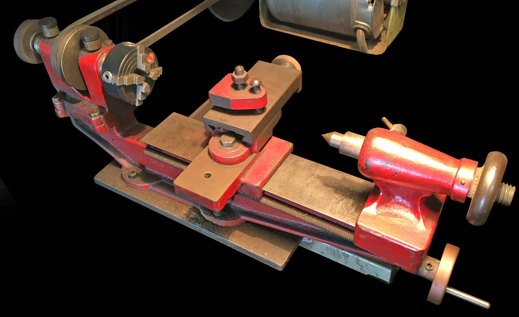
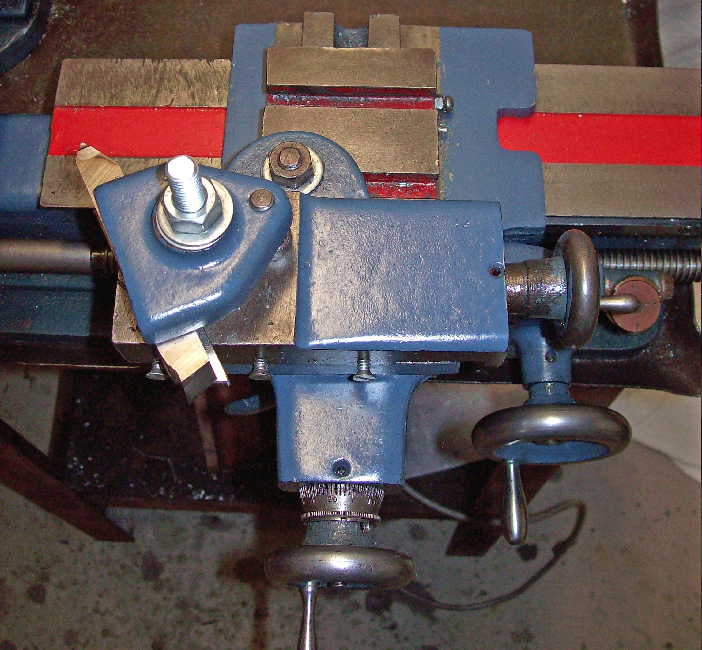
The apron was a heavy casting and both top and cross slides was cast with integral brackets on their front ends that allowed them extra travel by allowing to move well back over the ways. The carriage handwheel worked through reduction gearing for a slower and more controlled feed.
|
|
|
|
|
|
|
|
|
|
|
 |
|
|
|
|
|
|
|
|
|
|
|
|
|
|
|
|
|
 |
|
|
|
|
 |
|
|
|
|
|
|
|
|
|
|
|
Advance Lathe Continued Here Rebuilding an Advance Lathe
Other Australian-built lathes include: Bourke, Brackenbury & Austin, Clisby
Burden, Great Scot & Conrik, Hercus, Herbert, Premo, Qualos, Macson,
Mars, Nuttall, Parkanson, Purcell, Rexman, Rolfe, Sheraton, Tillico, T.N.C. & Veem
If you have a Mk. 2 Advance the writer
would be delighted to have photographs for display
Advance Lathe
email: tony@lathes.co.uk
Home Machine Tool Archive Machine-tools Sale & Wanted
Machine Tool Manuals Catalogues Belts Books Accessories
|
|
|