|
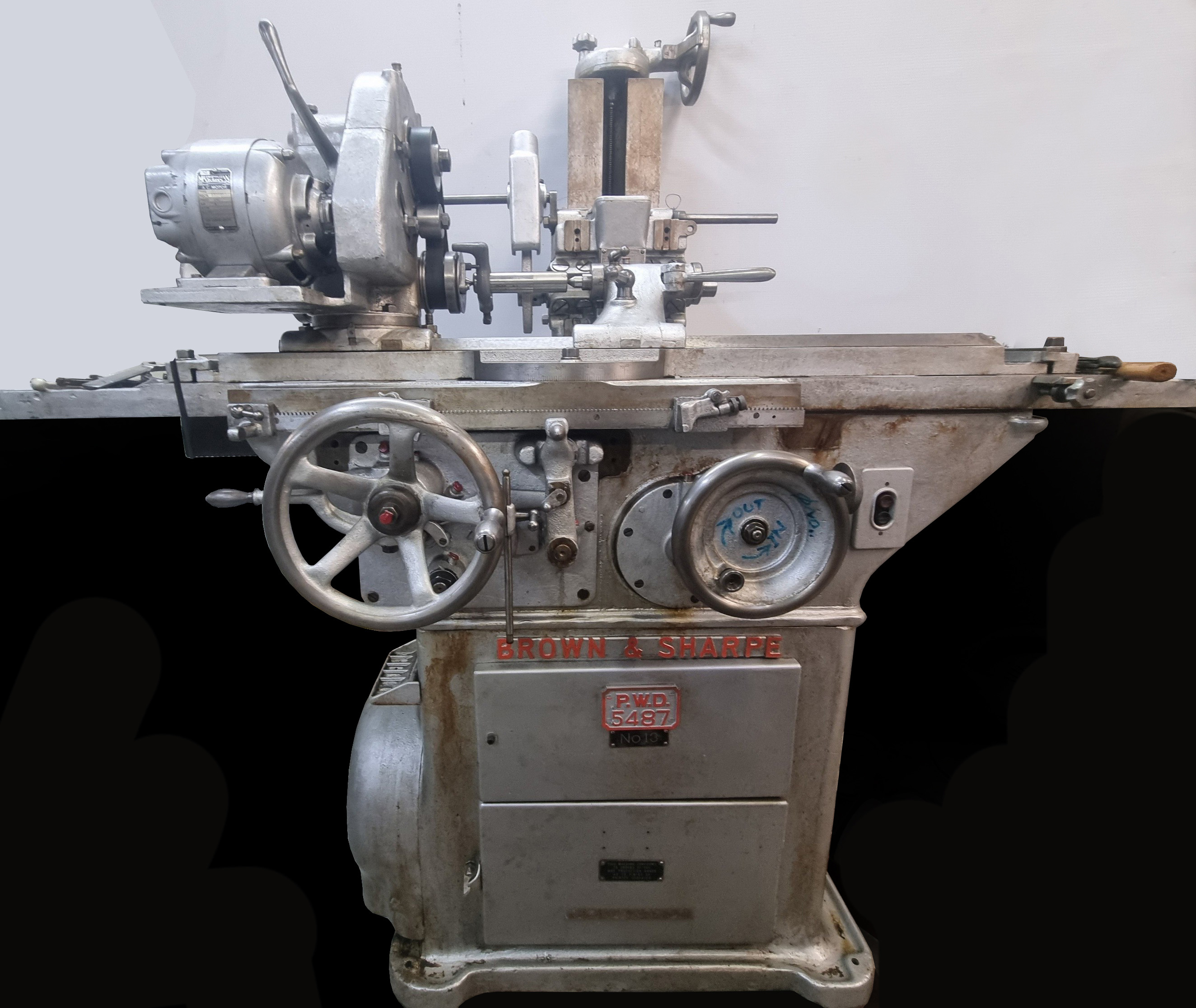
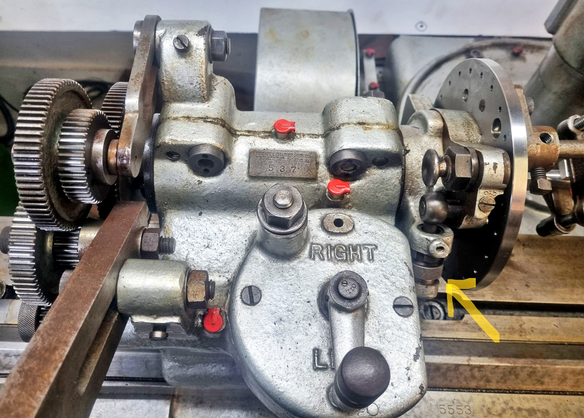
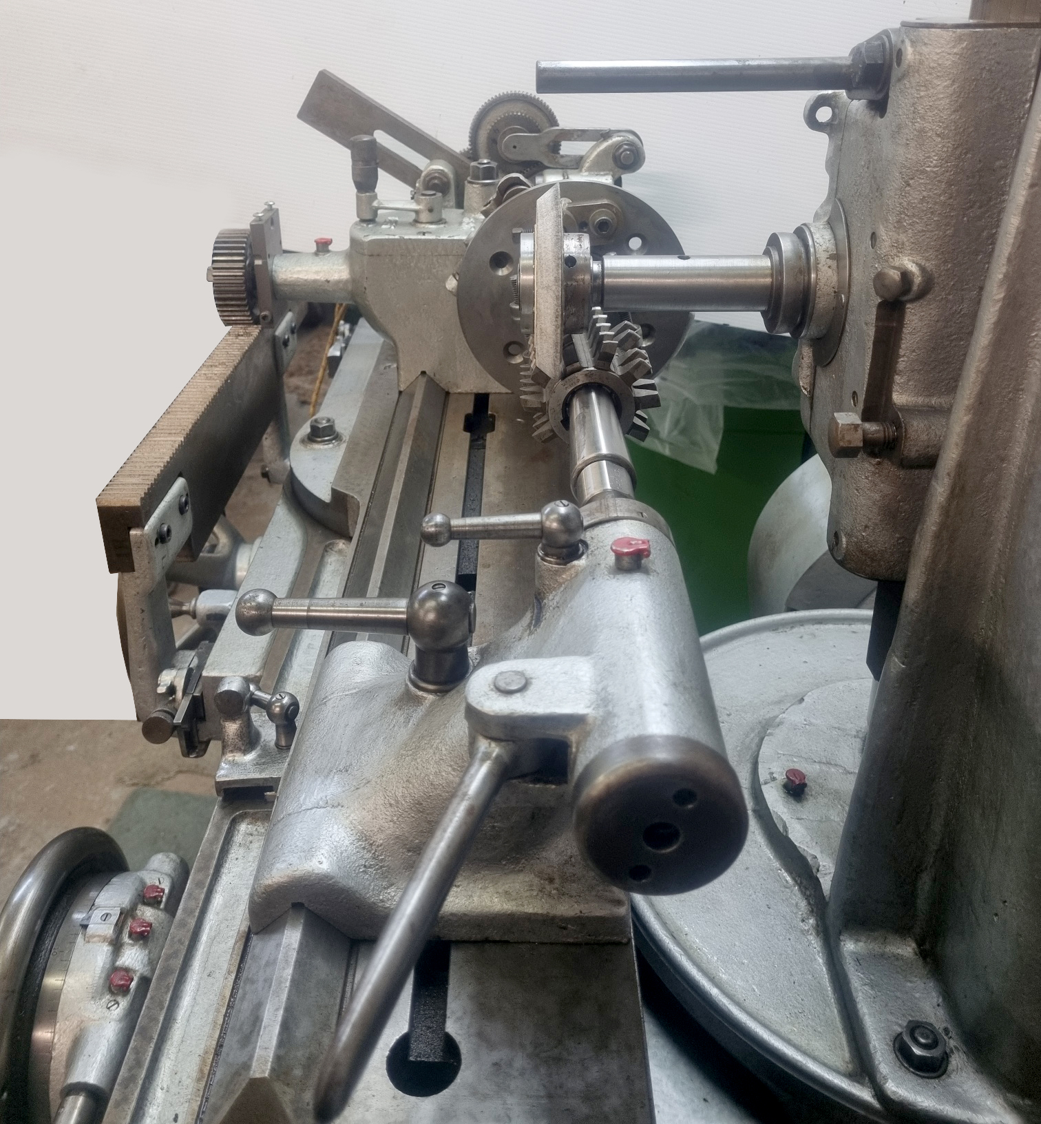
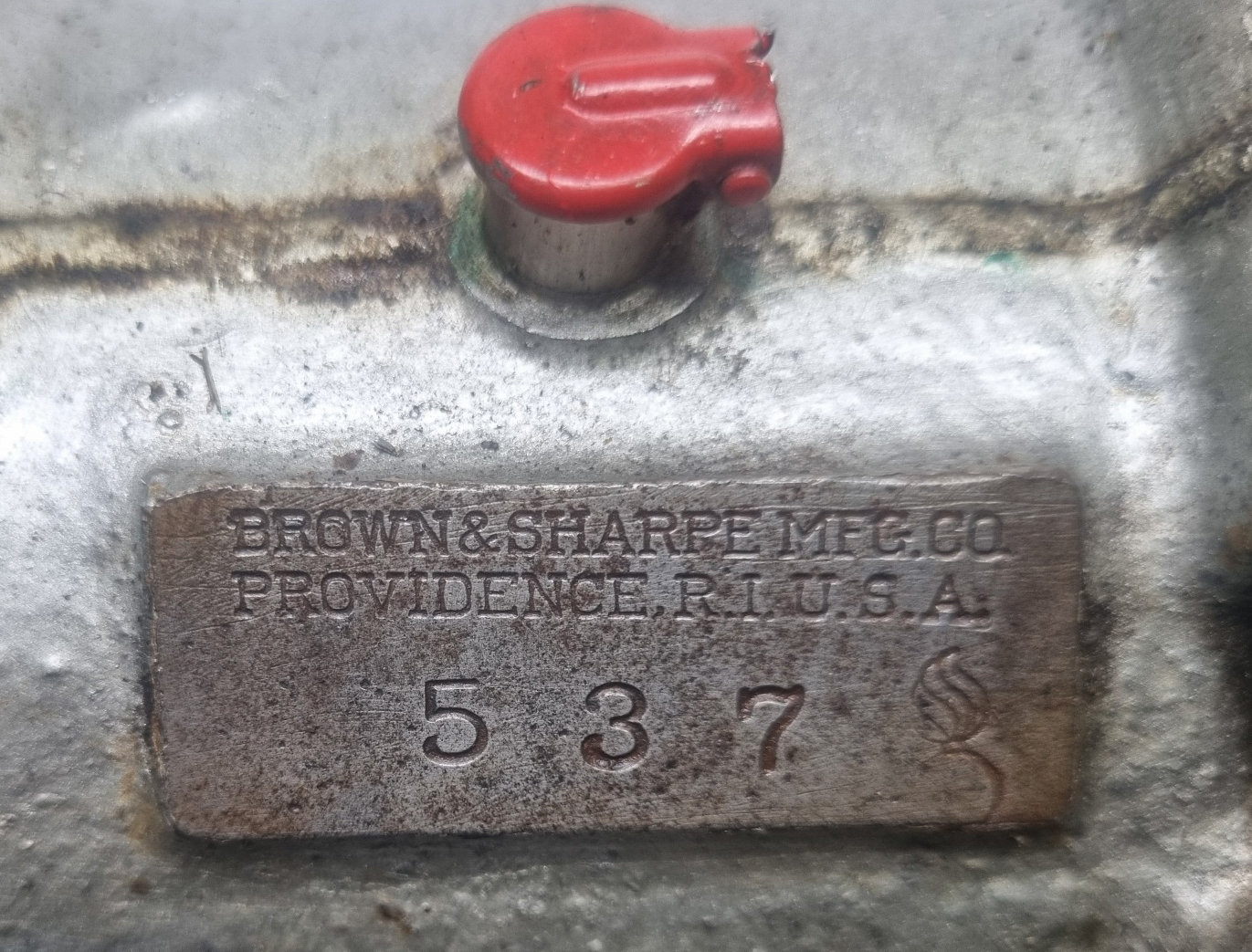
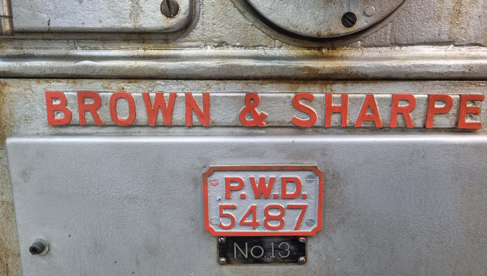
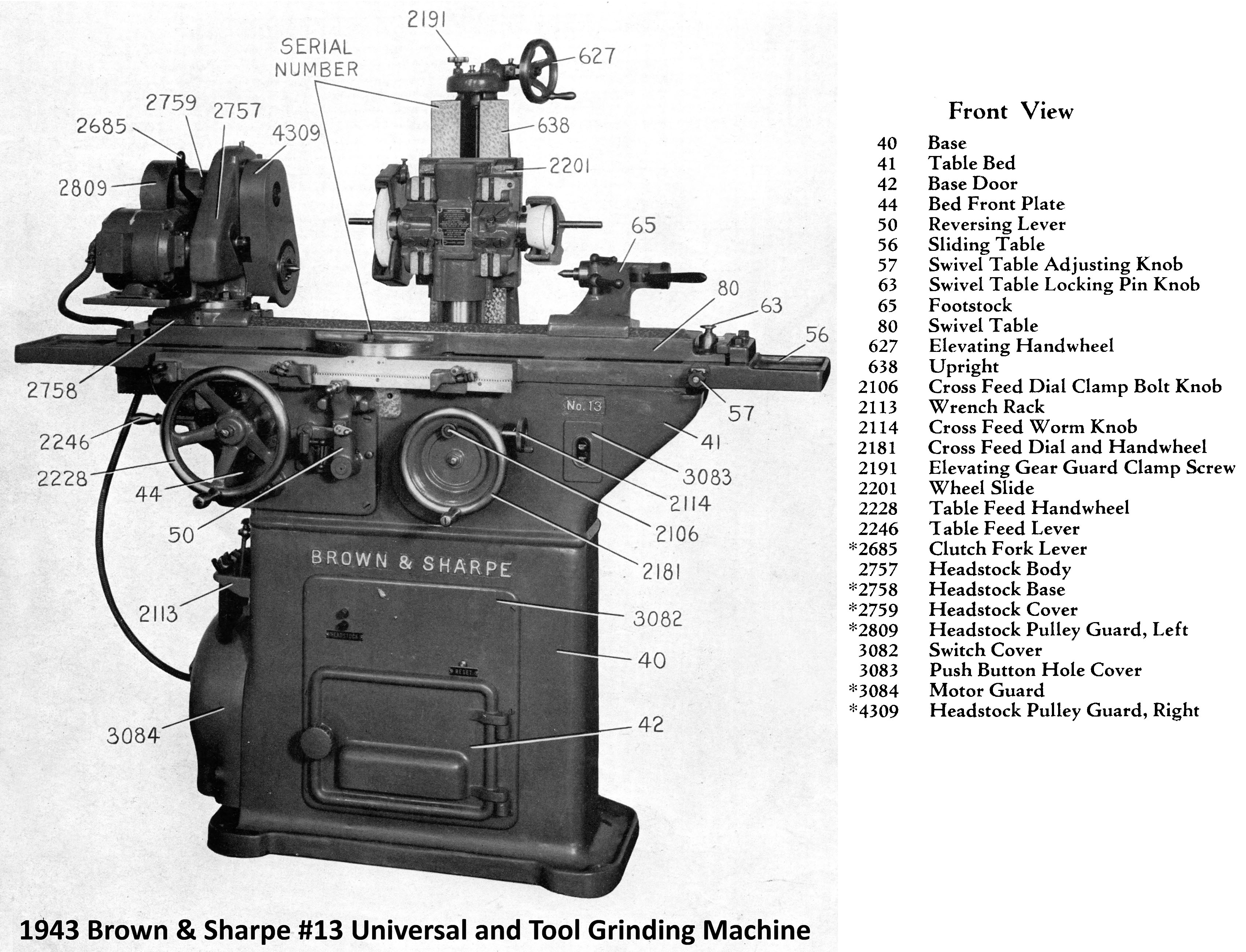
Highly versatile, as it was able to perform cylindrical, surface, internal and tool and cutter grinding, the Brown & Sharpe No.13 Universal Grinder shown below was built in 1943. Like so many machines tools made during WW2, carried a label proclaiming "War Finish", a clear intention to protect a reputation for offering machines with a high-quality, cosmetic finish. It also has a tag with the designation "PWD 5487", this being the asset number assigned by the New Zealand Public Works Department, the original owners of the machine.
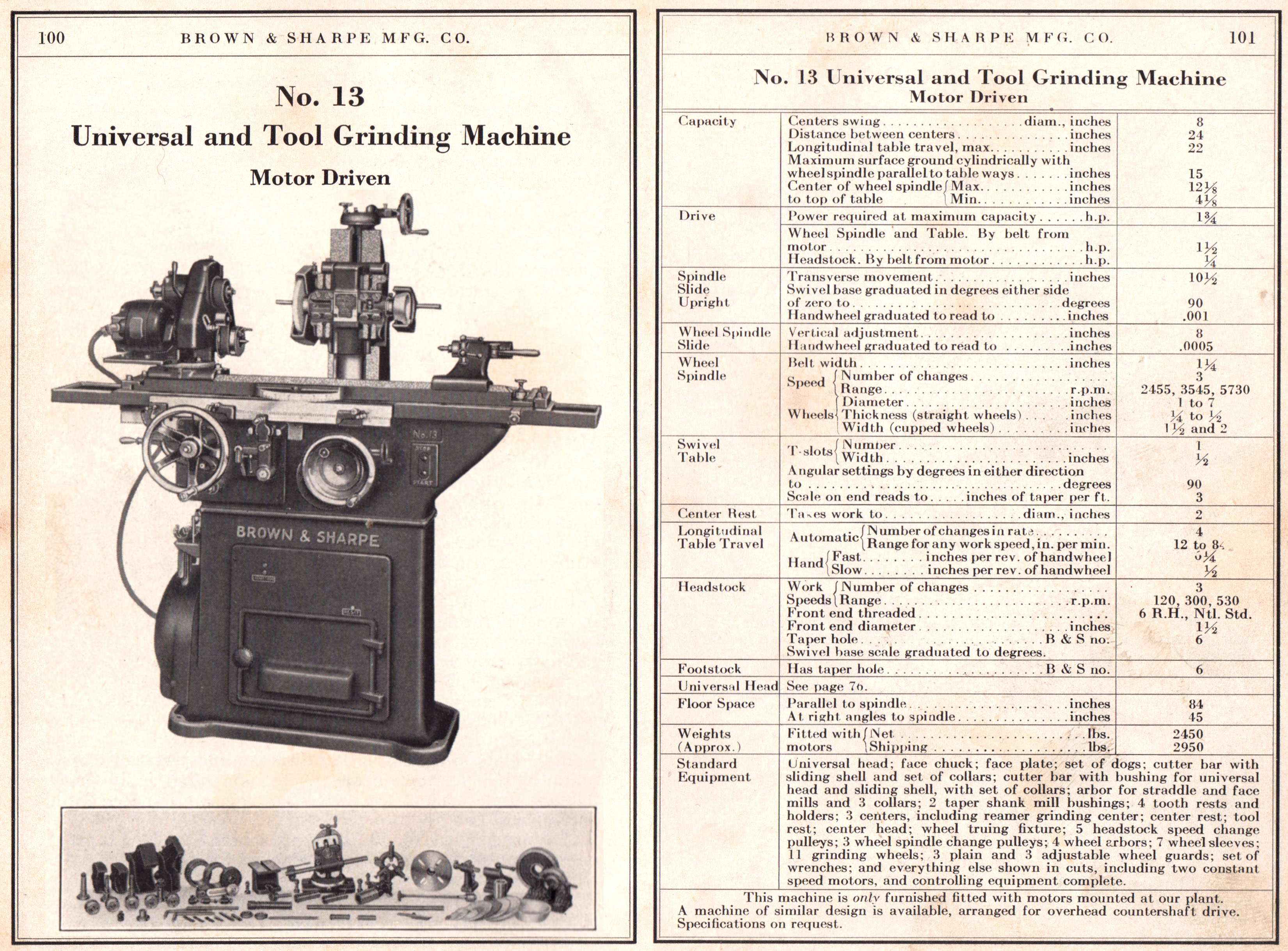
Able to take workpieces up to eight inches in diameter and twenty-four inches long, the grinder had a spindle head with its nose threaded 1.5" × 6 t.p.i. and capable of swivelling through a 90° arc from each side of its central axis. Arranged for both direct drive for chuck-mounted parts, and indirect for between-centres grinding, the drive system had three speeds: 120, 300, and 520 r.p.m. selected - rather slowly - by having to remove one pulley and installing another of a different size.
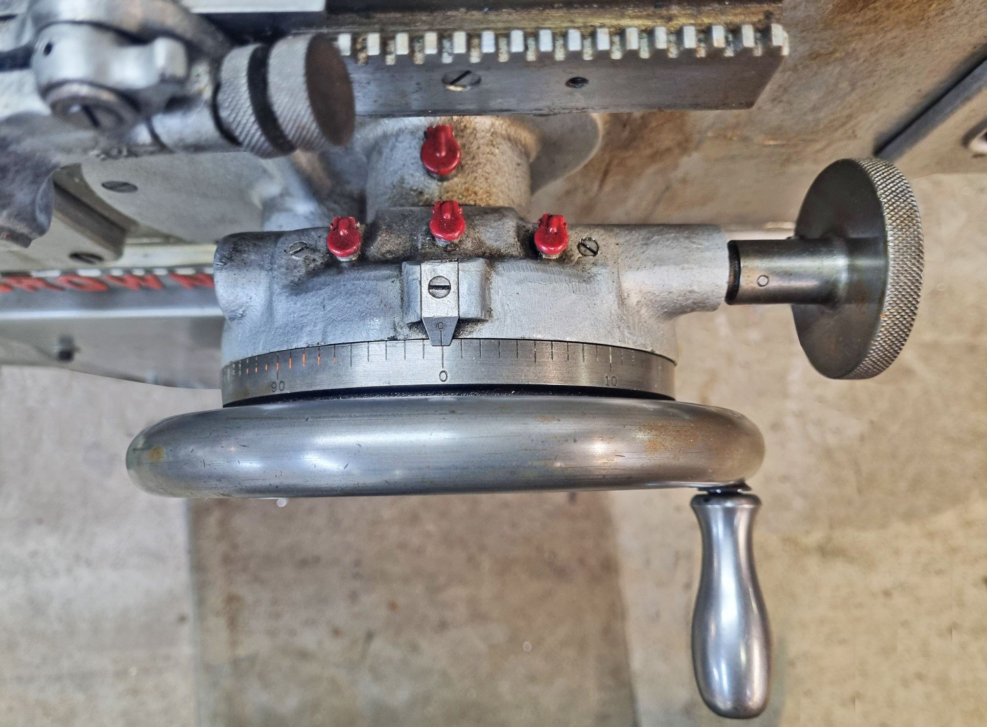
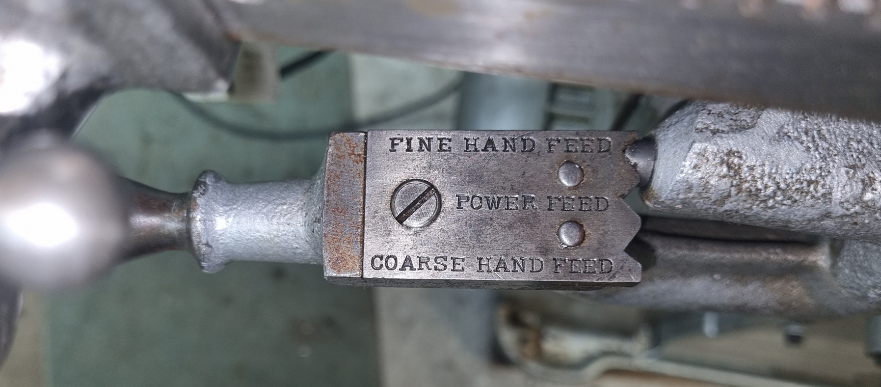
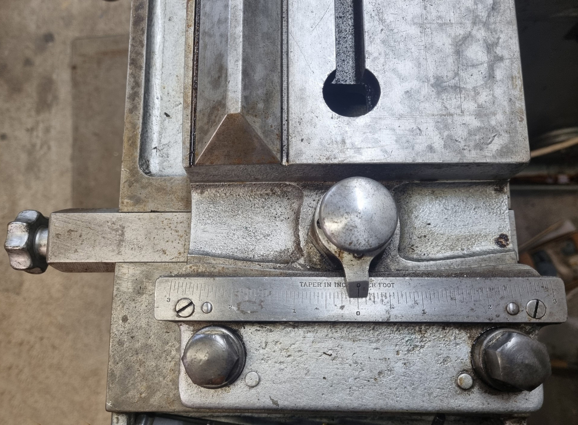
The table was equipped with a fine taper adjustment, graduated in inches per foot to a maximum length of three inches, that enabled such as smaller Morse tapers to be ground. The table, which ran on V-ways and flat slides, was lubricated by underside roller contact. Its longitudinal power feed, for both surface and cylindrical operations, was stepped through its four ratios via the cone pulley assembly. Fitted as part of the regular equipment was a mechanical reversing mechanism that allowed fine-limit adjustments with manual feeds provided in coarse and fine increments. Before being put into use, the makers recommended that the table be cycled back and forth to distribute oil and ensure free movement; unfortunately, lubrication was not centralized, instead at least twenty-nine red-painted oil caps required regular attention by the operator.
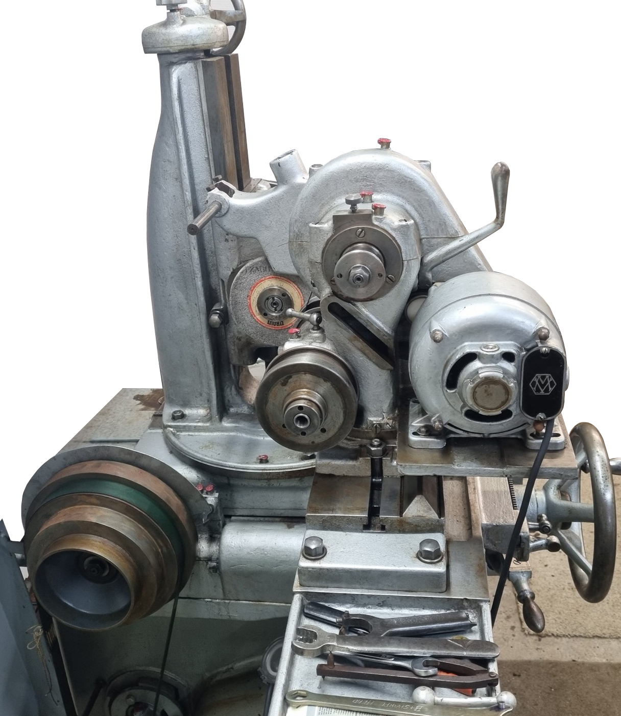
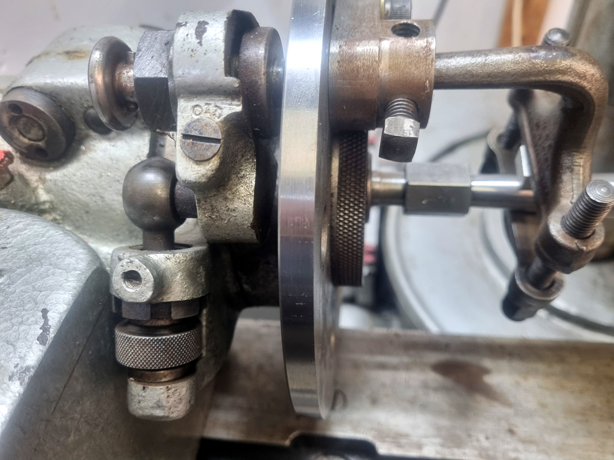
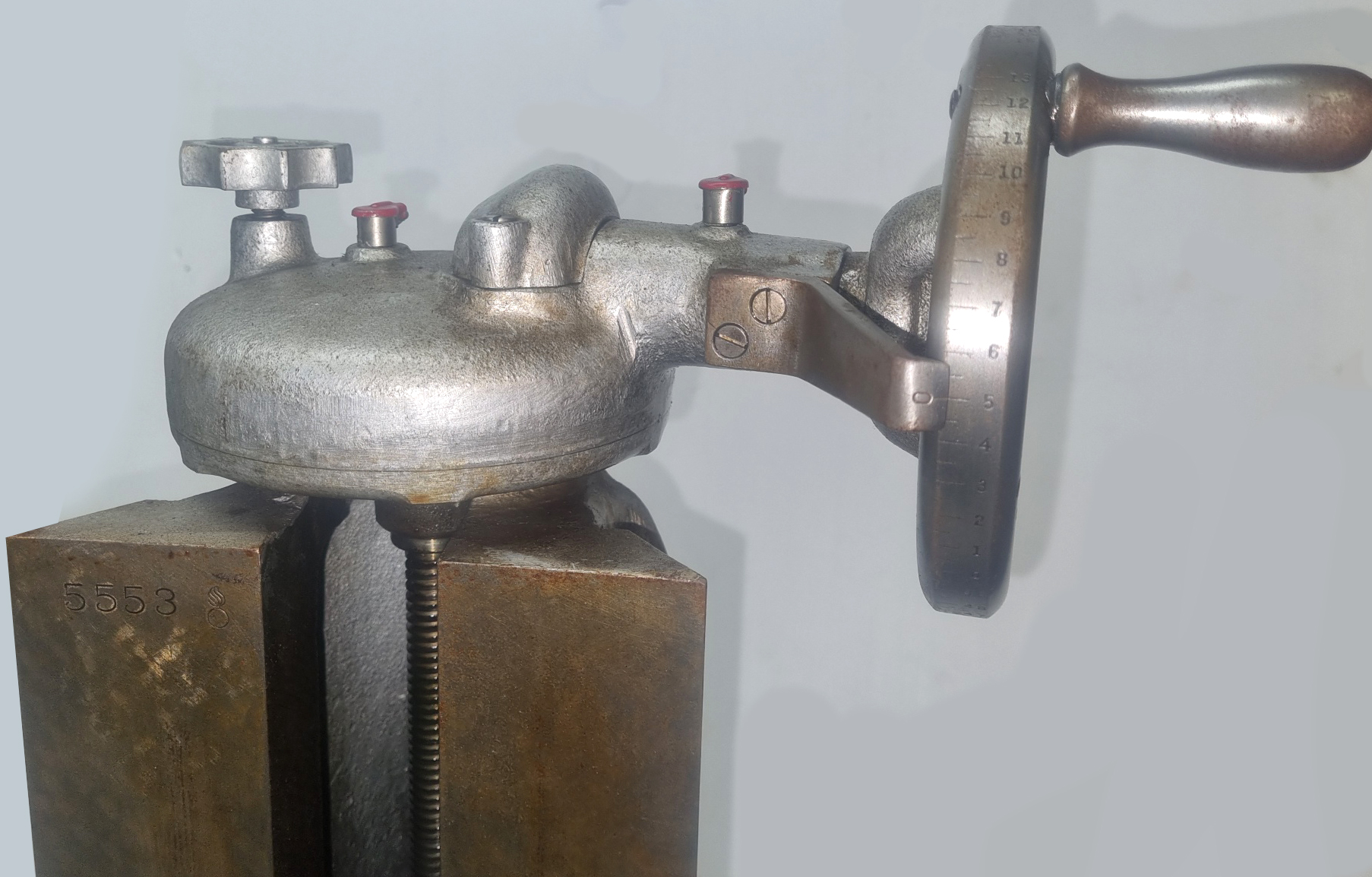
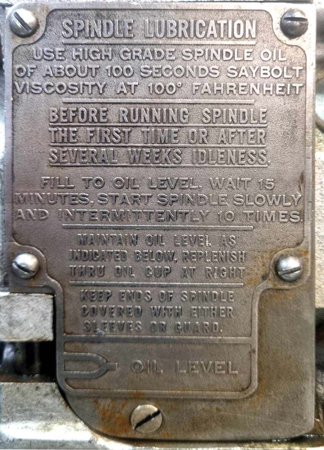
The grinding head was arranged to move eight inches vertically with graduations of 0.0005 inches per division, and could be rotated ±90° from its centerline, the drive belt being kept in constant tension (by the usual means on a grinder) of a counterweighted pulley at the rear of the machine. The grinding wheel spindle had speeds of 2,455, 3,545, and 5,730 r.p.m. (changed, again, by the inconvenient means of having to swap the drive pulley on the motor) and ran in plain, adjustable bearings that demanded careful start-up and lubrication. In this case, once in regular use, as a precaution "after several weeks idleness", the makers stated that the oil be filled to the correct level, followed by a wait of 15 minutes, and then the spindle, "started slowly and intermittently 10 times". In a demonstration of how well made this section of the machine was, one especially well-maintained example is known to have performed reliably for an astounding eighty-two years. The grinding head infeed was graduated in half-thousandth-inch increments, each graduation reducing the workpiece diameter by one thousandth of an inch, with a fine infeed handwheel able to advance the wheel head by 0.001 inches per revolution for 'sub-thousandth' accuracy.
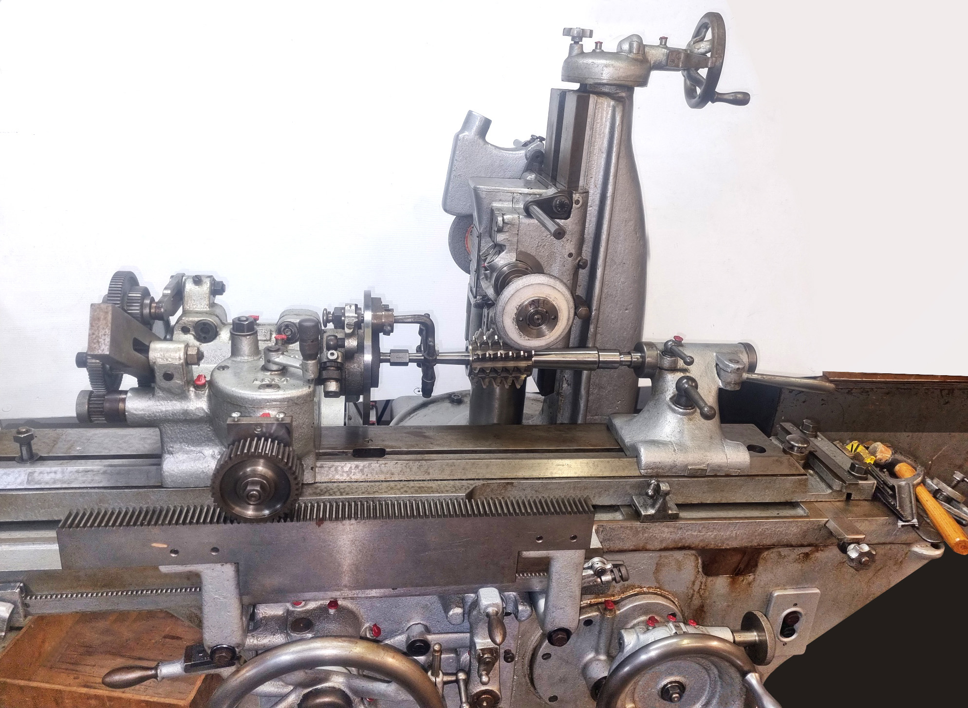
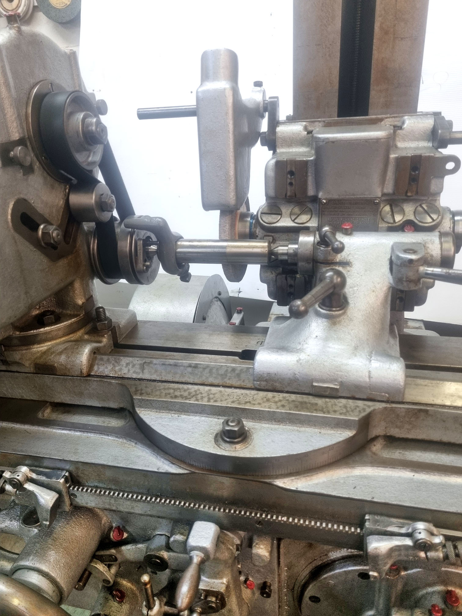
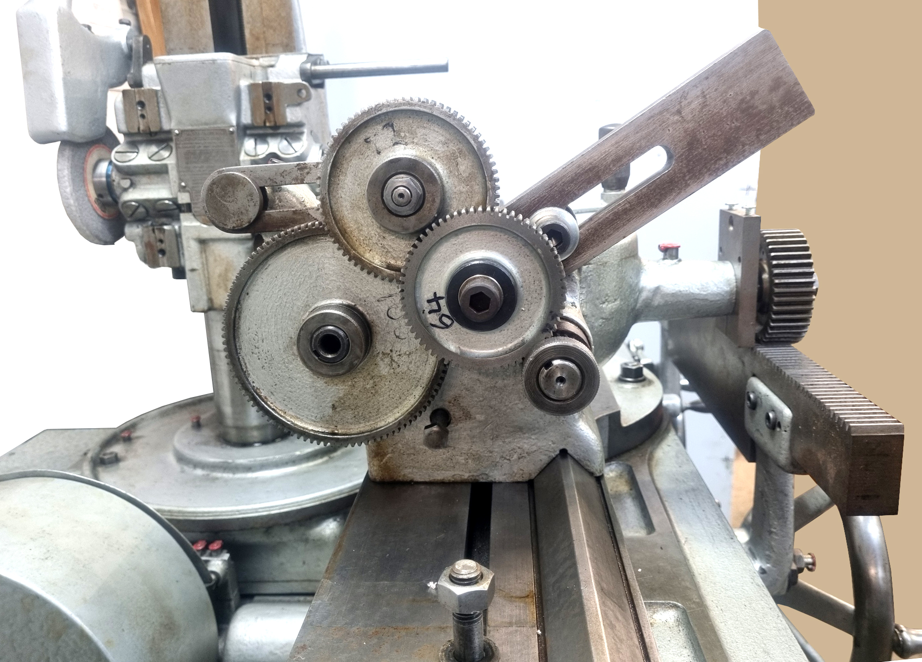
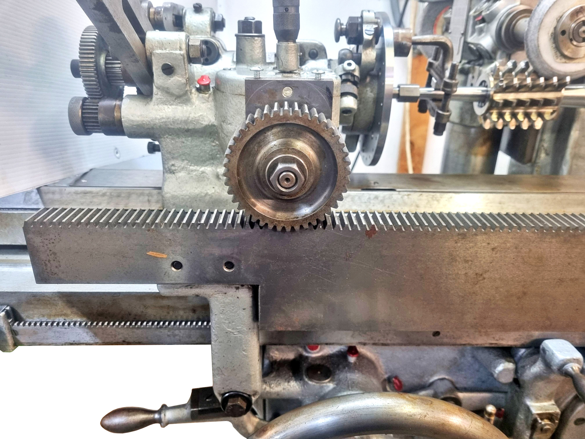
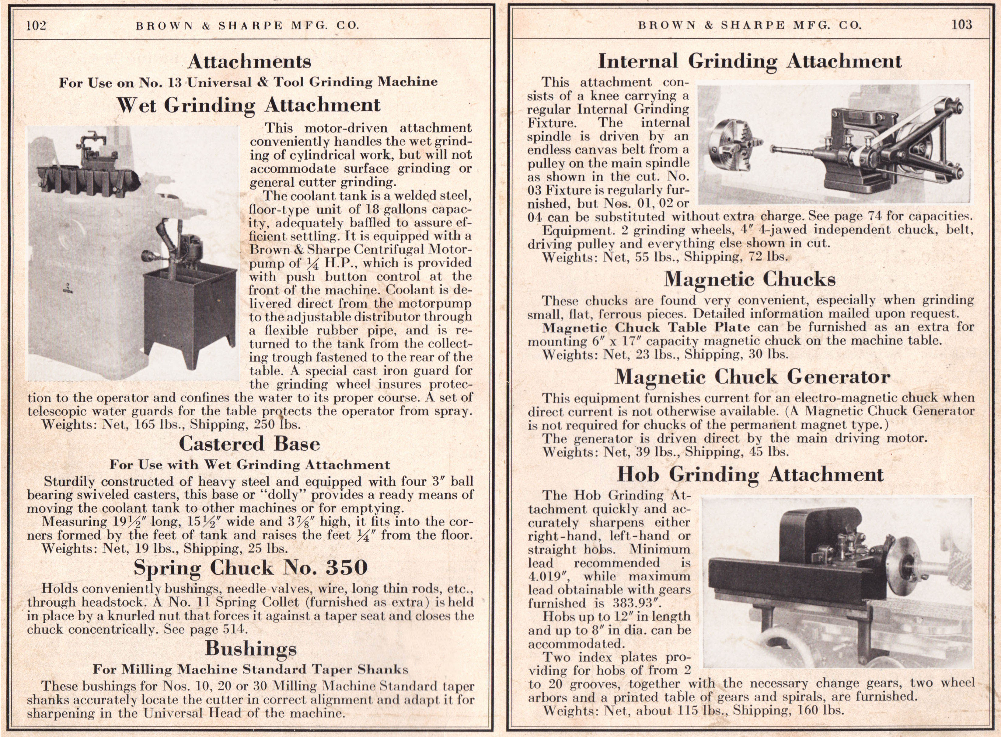
Available as an extra-cost accessory, the hob-grinding attachment used a rack-and-pinion drive to synchronize hob rotation with its spiral lead; in practice, a 180-inch lead was reproduced to within 0.83 inches using three pairs of compounded gears. Indexing relied on a dividing-disc and plunger system, with the radial depth set by a knurled knob, and a lever to select left or right-hand spirals. By removing the rack drive, this accessory was converted into a plain indexing head for non-spiral hobs and spline grinding.
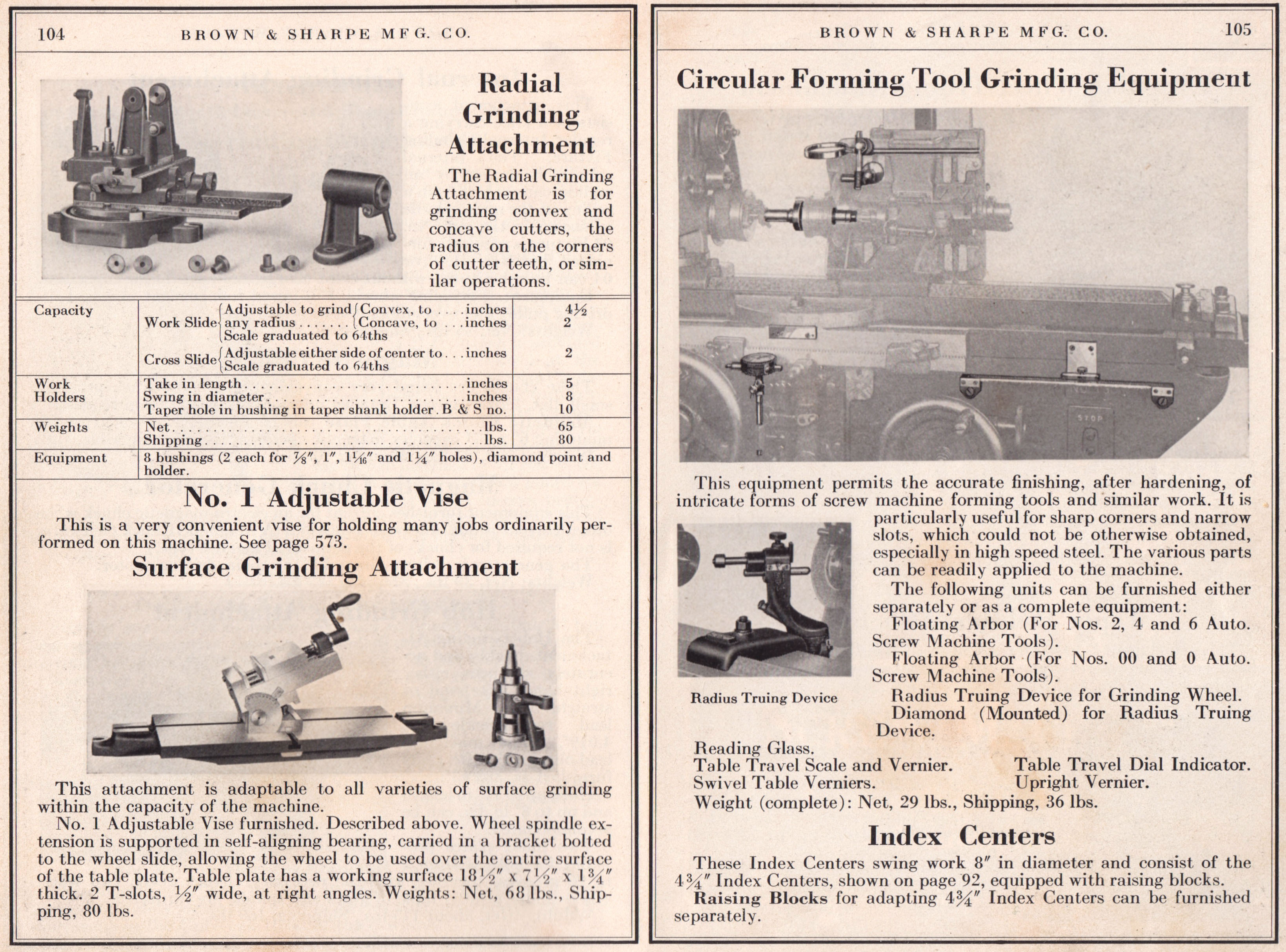
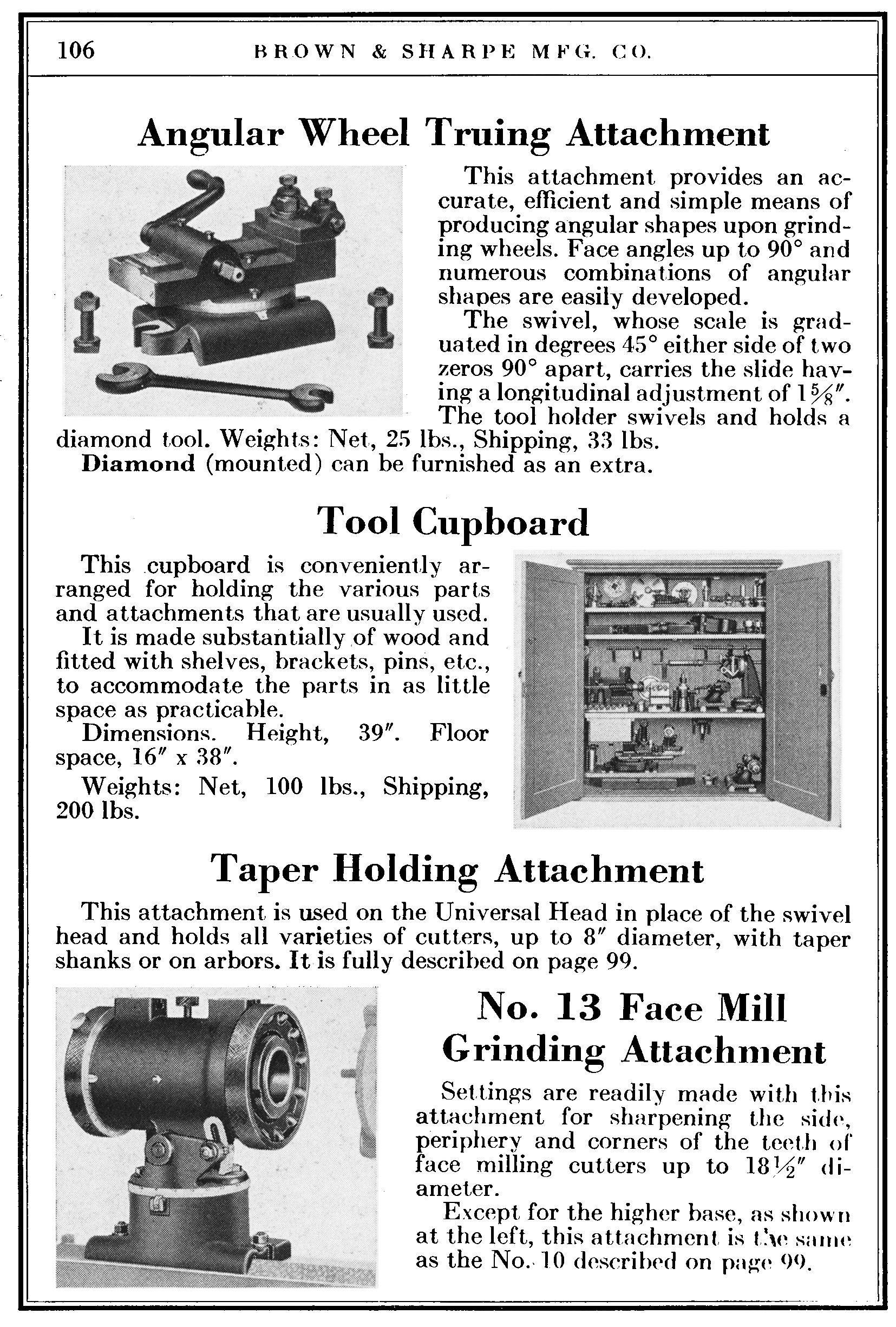
Other major accessories offered included a kit to allow wet grinding; internal, hob, radial, face, and circular-form grinding attachments; an angular-wheel truing attachment, a wooden tool cabinet, and magnetic chucks together with (if needed) an electrical generator that was run by a belt from the grinder
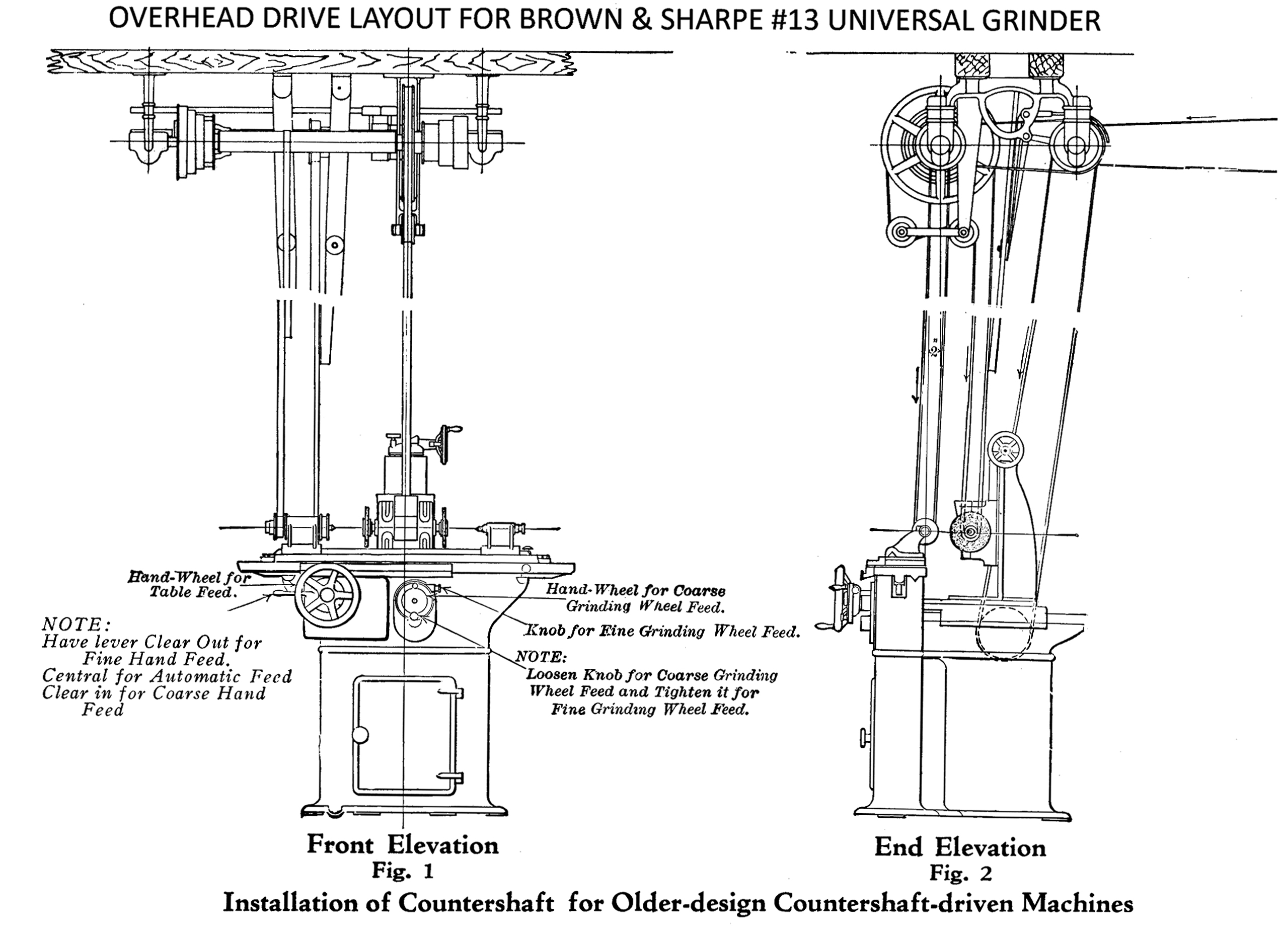
Early versions of the No.13 could be driven by either a wall or ceiling-mounted countershaft (or from line shafting in a factory), with one example of this type being used into the 1970s for the training of engineering apprentices. On this particular countershaft-driven model, four levers were provided for controlling the grinding wheel, workhead, table power feeds, and coolant pump. As this model would have had no connection to a supply of electricity, the belt-driven DC generator was provided to power the magnetic chuck, all these characteristics making it well-suited for use in small tool and die shops.
Grateful thanks are due to Murray Ballinger in New Zealand for providing the photographs and technical data..
|
|